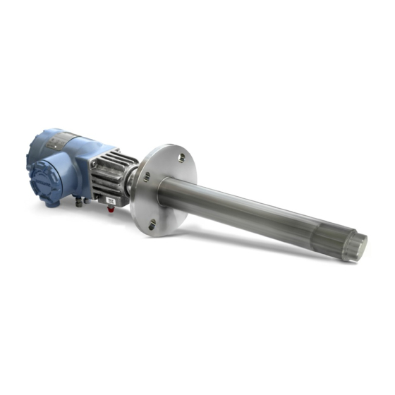
Emerson Rosemount 6888C Manual
In situ oxygen analyzer for hazardous areas
Hide thumbs
Also See for Rosemount 6888C:
- Instruction manual (88 pages) ,
- Quick start manual (48 pages) ,
- Quick start manual (40 pages)

Related Manuals for Emerson Rosemount 6888C


Summary of Contents for Emerson Rosemount 6888C
- Page 1 Manual 00809-0100-4891, Rev AB January 2023 Rosemount ™ 6888C In Situ Oxygen Analyzer For Hazardous Areas...
- Page 2 The following instructions must be adhered to and integrated into your safety program when installing, using, and maintaining Emerson products. Failure to follow the proper instructions may cause any one of the following situations to occur: loss of life, personal injury, property damage, damage to this instrument, and warranty invalidation.
- Page 3 NOTICE Highlights an essential operating procedure, condition, or statement. WARNING EXPLOSION Do not open when an explosive atmosphere may be present. WARNING ELECTRIC SHOCK Do not open while energized. WARNING Physical access Unauthorized personnel may potentially cause significant damage to and/or misconfiguration of end users’ equipment.
- Page 4 Safety instructions SAFETY INSTRUCTIONS FOR THE WIRING AND INSTALLATION OF THIS APPARATUS The following safety instructions apply specifically to all EU member states. They should be strictly adhered to in order to ensure compliance with the Low Voltage Directive. Non-EU states should also comply with the following unless superseded by local or national standards.
-
Page 5: Table Of Contents
5.1 Powering up the standalone Rosemount 6888 Transmitter probe (without Rosemount 6888 Xi)........................51 5.2 Power up the Rosemount 6888 Analyzer with single/dual channel or single channel and flame safety interlock Rosemount 6888Xi............52 5.3 Power up the Rosemount 6888C direct replacement probe (no electronics inside) with traditional architecture Rosemount 6888Xi..............52 Manual... - Page 6 Chapter 6 Calibration........................ 55 6.1 Manual/semi-automatic calibration..................55 6.2 Fully automatic calibration.......................56 ® Chapter 7 HART menu trees....................59 Chapter 8 Maintenance and service..................65 8.1 Overview.............................65 8.2 Maintenance intervals......................65 8.3 Repair............................66 Chapter 9 Replacement parts....................81 Chapter 10 Service support......................83 Appendix A Product certifications....................85 Rosemount 6888C...
-
Page 7: Chapter 1 General Information
(ambient or instrument air - always 20.95% O ) and the flue gases being measured. This manual covers the Rosemount 6888C, which is the hazardous area probe version. This probe can be configured as a blind stand-alone transmitter where HART ®... - Page 8 Care must be taken to ensure gas 1 and gas 2 calibration gases are properly configured if the tolerance check feature is enabled. 1.2.3 Hazardous Area Rosemount 6888C probe with General Purpose Rosemount Xi Electronics with flame safety interlock A flame safety interlock by Emerson is available for heater power disconnect ™...
- Page 9 Manual General information 00809-0100-4891 January 2023 1.2.5 Hazardous Area Rosemount 6888C probe with Integral Autocal and Foundation Fieldbus (FF) communications This probe contains gas-switching solenoids that can control the introduction of calibration gases for calibration. Calibrations can be initiated automatically via...
- Page 10 General information Manual January 2023 00809-0100-4891 Rosemount 6888C...
-
Page 11: Typical System Package
B. Quick Start Guide C. Optional mounting or adapter plate D. Optional traditional architecture cable E. HART Field Communicator package (optional) ® F. Optional reference & calibration gas accessories G. Rosemount 6888C probe H. Optional Rosemount 6888 XI Advanced Electronics Manual... -
Page 12: Rosemount 6888C Hazardous Area Probe Product Matrix
Typical system package Manual January 2023 00809-0100-4891 2.1 Rosemount 6888C Hazardous Area Probe product matrix Table 2-1: Rosemount 6888C Product Matrix Model Description Rosemount Transmitter approved for hazardous locations 6888C Measurement 1OXY Oxygen, standard sensing cell 2OXY Oxygen, high sulfur resistant sensing cell Probe length 18-in. - Page 13 Manual Typical system package 00809-0100-4891 January 2023 Table 2-1: Rosemount 6888C Product Matrix (continued) Adapter to existing ANSI 4 in. (101.6 mm), 150# flange Adapter to existing ANSI 6 in. (152.4 mm), 150# flange Adapter to existing ANSI 3 in. (76.2 mm), 300# flange Adapter to existing ANSI 4 in.
- Page 14 Typical system package Manual January 2023 00809-0100-4891 Rosemount 6888C...
-
Page 15: Specifications
Manual Specifications 00809-0100-4891 January 2023 3 Specifications 3.1 Measurement specifications 3.1.1 Net O range Variable 0 - 10% to 0-50% (Xi electronics of 0-50% range) 3.1.2 Accuracy in oxidizing condition ±0.75% of reading at 0.05% O , whichever is greater. ±1% of full scale for 0-10% ranges and above. -
Page 16: Environmental Specifications
3.3.1 Material NEMA 4X, polycarbonate material ® 3.3.2 Rosemount 6888 Xi ambient temperature limits -20 to -50 °C (-4 to 122 °F) Reduced cell life can be expected if operated continuously at temperatures above 705 °C (1300 °F). Rosemount 6888C... -
Page 17: Installation Specifications - Probe
Manual Specifications 00809-0100-4891 January 2023 3.3.3 Rosemount 6888 Xi temperature limits as measured inside the electronics housing -20 to 70 °C (-4 to 158 °F) 3.4 Installation specifications - probe 3.4.1 Probe mounting flange Vertical or horizontal-3 in. 150 6 in. (152.4 mm) bolt circle CAUTION Flanges are flat-faced and for mounting only. -
Page 18: Installation Specifications - Rosemount 6888 Xi With Rosemount 6888C Transmitter Probe
3.4.9 Power consumption of transmitter probe/integral autocal probe 776 W maximum during warm-up 3.5 Installation specifications - Rosemount 6888 Xi with Rosemount 6888C Transmitter probe 3.5.1 Electrical power of optional Rosemount 6888 Xi Electronics 120/240 V ±10%, 50/60 Hz 3.5.2 ... -
Page 19: Installation Specifications For Traditional Architechture Rosemount 6888 Xi For Use With Dr Or Other Probe
Optional loss of flame input Internally powered input to remove heater power actuated via dry contact output form proof of flame device. Emerson has satisfied all obligations coming from the European legislation to harmonize the product requirements in Europe. Manual... - Page 20 Specifications Manual January 2023 00809-0100-4891 Rosemount 6888C...
-
Page 21: Chapter 4 Install
Most combustion processes run only slightly negative or positive in pressure, so that the probe flange is for mechanical mounting only. The probe is not rated for high pressures. If this is a new installation, Emerson can supply a weld plate for welding to the flue gas duct. - Page 22 Rosemount 6888 Xi enclosure. CAUTION EQUIPMENT DAMAGE Failure to remove the protective membranes may cause the display to appear distorted. The membrane may be difficult or impossible to remove after extended use at elevated temperatures. Rosemount 6888C...
- Page 23 Manual Install 00809-0100-4891 January 2023 Figure 4-1: Wall/surface mount and pipe mount A. 4X cover screw B. Front panel C. 6X 1/2-in. NPT conduit openings D. Mounting bracket E. U-bolts F. 2-in. pipe supplied by customer Dimensions are in inches with millimeters in parentheses. Manual...
- Page 24 00809-0100-4891 Figure 4-2: Panel mount A. Maximum panel thickness 0.375 (9.52) B. Panel mount gasket C. 4X mounting brackets and screws provided D. 6X 1/2 in. NPT conduit openings NOTICE Dimensions are in inches with millimeters in parentheses. Rosemount 6888C...
-
Page 25: Electrical Installation
Manual Install 00809-0100-4891 January 2023 NOTICE The front panel is hinged at the bottom. The panel swings down for easy access to wiring locations. 4.3 Electrical installation All wiring must conform to local and national codes. Multiple wiring diagrams are shown in this section. Always refer to the diagrams that apply to your analyzer configuration and disregard all other wiring diagrams. -
Page 26: Connecting The Hazardous Area Transmitter Probe To The Rosemount General Purpose 6888 Xi Electronics
Rosemount 6888 Xi. 9. Connect the line, or L1, wire to the L1 terminal and the neutral, or L2, wire to the N terminal. 10. Reinstall the power supply connector in the power supply board. Rosemount 6888C... - Page 27 Manual Install 00809-0100-4891 January 2023 Figure 4-3: Single/dual channel wiring diagram Manual...
-
Page 28: Connecting The Analyzer Probe To The Single-Channel Safe Area Xi And Flame Safety Interlock
2. Remove the J1 and J2 connectors from the AC relay board. 3. Connect the AC line input to the J1 connector. 4. Connect the AC power to the Rosemount 6888C probe to the J2 connector. 5. Reinstall connector J1 and J2 to the AC relay board. - Page 29 Manual Install 00809-0100-4891 January 2023 Table 4-1: Housing and Electronics (continued) Integral autocal, transmitter electronics, Fieldbus communications Standard housing, direct replacement, no electronics 6DRY Standard housing, direct replacement, YEW electronics Rosemount 6888 Xi product matrix - safe area only Compare the configuration matrix below to the model number on the probe tag to confirm the features present in this specific probe.
- Page 30 Install Manual January 2023 00809-0100-4891 Figure 4-4: Single channel with flame safety wiring diagram Rosemount 6888C...
- Page 31 Manual Install 00809-0100-4891 January 2023 NOTICE A. See Rosemount 6888 Xi Instruction Manual for additional installation and operating instructions. B. All wiring marked with an asterisk (*) is factory wiring inside the Rosemount 6888 Xi. C. Except for JP5, JP7, and JP8 on the input/output (IO) board, jumper and switch settings are factory set and are shown for reference only.
- Page 32 C. Shield ground D. Channel #1 IO board E. AC input to P/S F. Plug G. Channel #2 alarm relay, SPS/IMPS H. Channel #2 4-20 mA/HART output I. Channel #1 Alarm relay, SPS/IMPS J. Channel #1 4-20 mA HART output Rosemount 6888C...
-
Page 33: Connect The Analyzer Probe With Integral Autocalibration To Hart ® Communications
Manual Install 00809-0100-4891 January 2023 4.6 Connect the analyzer probe with integral autocalibration to HART communications ® This probe contains gas-switching solenoids, Field Communicator, or Asset Management Solutions (AMS) software, so that the Rosemount 6888Xi Electronics can control the introduction of calibration gases. You can initiate calibrations in the following ways •... - Page 34 Install Manual January 2023 00809-0100-4891 Figure 4-6: Integral autocalibration and HART communications A. Ferrite clamp B. Signal C. Test points D. #8 pan htd scr (internal ground) E. Power F. Test point group Rosemount 6888C...
-
Page 35: Connect The Analyzer Probe With Integral Autocalibration To Foundation ™ Fieldbus Communications
Manual Install 00809-0100-4891 January 2023 Note A. Except for JP5, JP7, and JP8 on the input/output (IO) board, jumper and switch settings are factory set and are shown for reference only. B. IO board: 4-20 mA/HART loop power settings • — Pins 1-2: internal power Rosemount 6888Xi to Rosemount 6888 analyzer —... - Page 36 6. Follow the remaining electrical installation instructions for the Rosemount 6888 Xi included with your system configuration. Rosemount 6888C ordering information Compare the ordering information below to the model number on the probe tag to confirm the features present in this specific probe.
- Page 37 Manual Install 00809-0100-4891 January 2023 Figure 4-7: Integral autocalibration and F Fieldbus communication OUNDATION without optional Rosemount 6888Xi A. Signal B. Not used C. #8 pan htr scr (internal ground) D. Power E. Probe test point group NOTICE A. All wiring marked with an asterisk (*) is factory wiring inside the Rosemount 6888 Xi.
- Page 38 Install Manual January 2023 00809-0100-4891 Table 4-4: Remote type ordering information 1OXY Single channel O 2OXY Single channel O with flame safety interlock for heater 3OXY Dual channel O 4OXY Single channel O traditional architecture for 120 V probes Rosemount 6888C...
- Page 39 Manual Install 00809-0100-4891 January 2023 Figure 4-8: Integral autocalibration and F Fieldbus communication OUNDATION with optional Rosemount 6888Xi A. Ribbon cable to display board J2 Sensor 1 B. Signal C. HART connection (Used as a communication bus from probe analyzer ® electronics to optional Rosemount 6888Xi.
- Page 40 • Pins 2-3: external power Rosemount 6888Xi to Rosemount 6888 Analyzer (requires 2,500 resistor across J4, PR+ to PR-). JP7/JP8 • Pins 1-2: internal power Rosemount 6888Xi to DCS. • Pins 2-3: external power Rosemount 6888Xi to DCS. Rosemount 6888C...
-
Page 41: Connecting The Traditional Architecture To The Direct Replacement Hazardous Area Replacement Probe (No Electronics Inside)
Manual Install 00809-0100-4891 January 2023 Figure 4-9: Rosemount 6888 Xi front and bottom view A. Power supply board B. AC relay board C. Shield ground D. IO board E. AC input to power supply F. Plug G. AC input to relay board H. - Page 42 Table 4-6: Remote Type 1OXY Single channel O 2OXY Single channel O with flame safety interlock for heater 3OXY Dual channel O 4OXY Single channel O traditional architecture for 120 V probes Rosemount 6888C...
-
Page 43: Connect Traditional Architecture System To The Direct Replacement Probe
Manual Install 00809-0100-4891 January 2023 Figure 4-10: Traditional architecture with direct replacement hazardous area replacement probe (no electronics inside) NOTICE A. See Rosemount 6888 Xi Instruction Manual for additional installation and operating instructions. B. All wiring marked with an asterisk (*) is factory wiring inside the Rosemount 6888 Xi. C. - Page 44 Press the insert in until it bottoms out in the gland body. h) Slide the locking nut up and thread it onto the gland body. Tighten the locking nut so the rubber grommet inside the plastic insert compresses against the cable wall to provide an environmental seal. Rosemount 6888C...
- Page 45 Manual Install 00809-0100-4891 January 2023 4. At the Rosemount 6888Xi, connect the cable leads to the connectors on the analyzer input/output (IO) board. Figure 4-11: Traditional architecture general purpose cable gland assembly WARNING ELECTRIC SHOCK Disconnect and lock out power before working on any electrical components. There is voltage up to 240 Vac.
- Page 46 B. All wiring marked with an asterisk (*) is factory wiring inside the Rosemount 6888 Xi. C. Except for JP7 and JP8 on IO board, jumper and switch settings are factory set and are shown for reference only. Rosemount 6888C...
- Page 47 Manual Install 00809-0100-4891 January 2023 Figure 4-13: Traditional architecture with direct replacement probe (no electronics inside) A. Power supply board B. DR board C. Shield ground D. IO board E. Plug F. Probe cable G. AC input H. Alarm relay, Rosemount SPS I.
-
Page 48: Pneumatic Installation
January 2023 00809-0100-4891 4.10 Pneumatic installation 4.10.1 Reference air package After the Rosemount 6888C is installed, connect the reference air set to the analyzer unit. Refer to the schematic diagram in Figure 4-14 for a locally assembled reference air supply. Instrument air (reference air): 5 psig (0.34 barg) minimum, 8 psig (0.55 barg) maximum at 2.0 scfh (1.01 L/min) maximum;... - Page 49 Manual Install 00809-0100-4891 January 2023 Figure 4-15: Plant air schematic diagram, accessory housing A. Vent B. Calibration gas 1: ¼-in. tube C. Calibration gas 2: ¼-in. tube D. To analyzer E. Reference air flow meter F. Instrument air supply: 10 psig (0.69 barg) to 80 psig (5.52 barg) pressure G.
- Page 50 Install Manual January 2023 00809-0100-4891 Figure 4-16: Manual calibration panel Note Dimensions are in inches with millimeters in parentheses. Rosemount 6888C...
-
Page 51: Chapter 5 Power Up
5.1 Powering up the standalone Rosemount 6888 Transmitter probe (without Rosemount 6888 Xi) Complete the following steps to power up the Rosemount 6888C Transmitter probe. Procedure 1. Apply AC line power to the transmitter. 2. Apply 24 Vdc loop power to the transmitter. -
Page 52: Power Up The Rosemount 6888 Analyzer With Single/Dual Channel Or Single Channel And Flame Safety Interlock Rosemount 6888Xi
4-20 mA output is based on the default range of 0-10% O If there is an error condition at startup, an alarm message is displayed on the Rosemount 6888Xi. 5.3 Power up the Rosemount 6888C direct replacement probe (no electronics inside) with traditional architecture Rosemount 6888Xi Procedure 1. -
Page 53: Run Rosemount 6888Xi Quick Start Wizard
Manual Power up 00809-0100-4891 January 2023 The analyzer probe takes approximately 45 minutes to warm up to the 1,357 °F (736 °C) heater set point. The 4-20 mA signal remains at a default value of 3.5 mA, and the O reading remains at 0 percent through this warm-up period. After warm-up, the probe begins reading oxygen, and the 4-20 mA output is based on the default range of 0 to 10 percent O If there is an error condition at start-up, the Rosemount 6888Xi displays an alarm... -
Page 54: Re-Initiating Rosemount 6888 Xi Wizard
10. Press Enter to continue. 11. When prompted, use the Up and Down keys to select Yes. 12. Press Enter to continue. The Rosemount 6888 Xi displays several screens while saving the configuration, resets itself, and then displays the Wizard screen. Rosemount 6888C... -
Page 55: Chapter 6 Calibration
January 2023 6 Calibration You can calibrate the Rosemount 6888C in the installed condition without removing the instrument from the process duct and also while the combustion process is online. A stainless steel tube runs the length of the probe and delivers the calibration gases into the cell area. -
Page 56: Fully Automatic Calibration
DCS. Calibration setup is found under the detailed setup menu. Rosemount 6888C... - Page 57 Manual Calibration 00809-0100-4891 January 2023 6.2.2 Probe with integral autocal housing This probe contains the autocal solenoids within the blue electronics housing, eliminating the need and cost for an SPS or IMPS solenoid enclosure. Both calibration gases are permanently piped into two ports on the probe. It's important to confirm that there are no piping leaks or the calibration bottles will leak down permanently.
- Page 58 Calibration Manual January 2023 00809-0100-4891 Rosemount 6888C...
-
Page 59: Hart ® Menu Trees
Manual HART menu trees ® 00809-0100-4891 January 2023 7 HART menu trees ® Figure 7-1: Rosemount 6888 Xi (page 1) Manual... - Page 60 HART menu trees Manual ® January 2023 00809-0100-4891 Figure 7-2: Rosemount 6888 Xi (continued) Rosemount 6888C...
- Page 61 Manual HART menu trees ® 00809-0100-4891 January 2023 Figure 7-3: Rosemount 6888 Xi (continued) Manual...
- Page 62 HART menu trees Manual ® January 2023 00809-0100-4891 Figure 7-4: Field Communicator Rosemount 6888C...
- Page 63 Manual HART menu trees ® 00809-0100-4891 January 2023 Manual...
- Page 64 HART menu trees Manual ® January 2023 00809-0100-4891 Rosemount 6888C...
-
Page 65: Maintenance And Service
8 Maintenance and service 8.1 Overview This section identifies the calibration methods available and provides the procedures to maintain and service the Rosemount 6888C O transmitter. WARNING ELECTRIC SHOCK Install all protective equipment covers and safety ground leads after equipment repair or service. -
Page 66: Repair
8.3 Repair Each of the following procedures details how to remove and replace a specific component of the Rosemount 6888C. WARNING BURNS Remove the transmitter from the stack for all service activities. Allow the unit to cool and take it to a clean work area. Failure to comply may cause severe burns. - Page 67 Manual Maintenance and service 00809-0100-4891 January 2023 Replace probe Complete the following steps to replace the probe in the stack. Procedure 1. Bolt the transmitter to the stack and install the insulation. 2. Connect all signal and power leads at the probe. Refer to Install for detailed wiring instructions.
- Page 68 Replacement transmitter boards come in two configurations: a. Transmitter board with thermal pad and mounting screws b. Transmitter board, thermal pad, plastic cover, mounting plate, and mounting screws Rosemount 6888C...
- Page 69 Manual Maintenance and service 00809-0100-4891 January 2023 6. Do one of the following: • If only the transmitter board is being replaced, carefully unsnap the plastic cover from the old transmitter board and then snap it onto the new board. Make sure to place the cover so that the screw terminals for the power and signal wiring fit into the openings.
- Page 70 See Figure 8-2 for letter references. The DR board is available as a standalone kit or with the plastic cover and mounting plate. WARNING ELECTRIC SHOCK Disconnect and lock out power before working on any electrical components. Rosemount 6888C...
- Page 71 Manual Maintenance and service 00809-0100-4891 January 2023 Figure 8-2: DR terminal board mounting A. Cover B. Plastic cover C. DR terminal board D. Mounting plate E. Screws F. Screws Procedure 1. Remove cover (A) from the DR probe housing. 2. Disconnect the power and signal wires from the DR terminal board (C). 3.
- Page 72 Use heat resistant gloves and clothing when removing probe. Do not attempt to work on the probe until it has cooled to room temperature. The probe can be as hot as 427 °C (800 °F). This can cause severe burns. Rosemount 6888C...
- Page 73 Manual Maintenance and service 00809-0100-4891 January 2023 Figure 8-3: Housing/Strut Exploded View A. Cover B. Plastic cover C. Transmitter board D. Mounting plate E. Housing screws F. Thermal pad G. Screws H. Strut clamp I. O-ring J. Screws K. Viton tube L.
- Page 74 Probe components can be as hot as 300 °C (572 °F). This can cause severe burns. Disconnect and lock out power before working on any electrical components. There is voltage up to 240 Vac. Rosemount 6888C...
- Page 75 Manual Maintenance and service 00809-0100-4891 January 2023 CAUTION EQUIPMENT DAMAGE Do not remove the cell unless you are certain it needs to be replaced. Removal may damage the cell and platinum pad. Follow the complete troubleshooting procedure to make sure the cell needs to be replaced before removing it. Figure 8-4: Cell Replacement Kit A.
- Page 76 23. Using pin spanner wrenches, torque to 10 ft-lb (14 N m). 24. If applicable, reinstall the vee deflector, orienting apex toward gas flow. 25. Secure with setscrews and anti-seize compound. 26. Torque to 25 in-lb (2.8 N m). Rosemount 6888C...
- Page 77 Manual Maintenance and service 00809-0100-4891 January 2023 27. On systems equipped with an abrasive shield, install the dust gaskets with joints 180 ° apart. 28. Follow the instructions in Remove and replace probe to install the transmitter to the stack or duct. 29.
- Page 78 (E). Inspect sets crews. If damaged, replace with stainless sets crews coated with anti-seize compound. 3. Follow the instructions in Remove and replace probe to install the probe into the stack or duct. Rosemount 6888C...
- Page 79 Manual Maintenance and service 00809-0100-4891 January 2023 8.3.7 Replace blind cover This section covers the replacement of the main housing cover and the application of the correct field wiring label. NOTICE Field wiring labels are supplied for each product configuration. Ensure the correct label is applied to the inside of the cover that matches your configuration.
- Page 80 A graphic of each label and its application is shown in Figure 8-6. 3. Peel off the backing. 4. Attach the new label to the inside of the new cover. 5. Install the new cover onto the housing. Rosemount 6888C...
-
Page 81: Chapter 9 Replacement Parts
Manual Replacement parts 00809-0100-4891 January 2023 9 Replacement parts Table 9-1: Replacement Part Kits for O Transmitter Part Number Description 6A00448G01 Kit, transmitter board 6A00448G02 Kit, transmitter board with mounting plate and cover 6A00449G01 Kit, DR terminal board 6A00449G02 Kit, DR terminal board with mounting plate and cover 6A00449G10 Kit, DR terminal board, YEW 6A00449G11... - Page 82 Replacement parts Manual January 2023 00809-0100-4891 Table 9-1: Replacement Part Kits for O Transmitter (continued) 1A99119G02 Two flow regulators (for calibration gas bottles) 1A99119G03 Bottle rack Calibration gas bottles cannot be shipped via air freight. Rosemount 6888C...
-
Page 83: Chapter 10 Service Support
To expedite the return process outside of the United States, contact the nearest Rosemount representative. ™ Within the United States, call the Emerson Instrument and Valves Response ™ Center using the 1-800-654-RSMT (7768) toll-free number. This center, available 24 hours a day, will assist you with any needed information or materials. - Page 84 Service support Manual January 2023 00809-0100-4891 Rosemount 6888C...
-
Page 85: Appendix A Product Certifications
Manual Product certifications 00809-0100-4891 January 2023 A Product certifications For product certifications and the Declaration of Conformity, see the Rosemount 6888C Quick Start Guide. The most recent revision of the Declaration of Conformity can be found at Emerson.com/Rosemount. Manual... - Page 86 Emerson Terms and Conditions of Sale are available upon request. The Emerson logo is a trademark and service mark of Emerson Electric Co. Rosemount is a mark of one of the Emerson family of companies. All other marks are the property of their respective owners.
Need help?
Do you have a question about the Rosemount 6888C and is the answer not in the manual?
Questions and answers