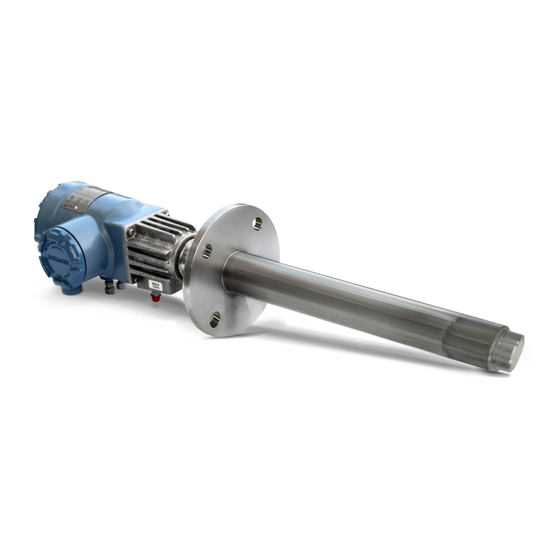
Emerson Rosemount 6888C Instruction Manual
In-situ combustion oxygen analyzer for use in hazardous areas
Hide thumbs
Also See for Rosemount 6888C:
- Manual (86 pages) ,
- Quick start manual (48 pages) ,
- Quick start manual (40 pages)

Related Manuals for Emerson Rosemount 6888C


Summary of Contents for Emerson Rosemount 6888C
- Page 1 Instruction Manual 00809-0100-4891, Rev AA July 2018 ™ Rosemount 6888C In-Situ Combustion Oxygen Analyzer For use in Hazardous Areas...
- Page 2 The following instructions must be adhered to and integrated into your safety program when installing, using, and maintaining Emerson products. Failure to follow the proper instructions may cause any one of the following situations to occur: loss of life, personal injury, property damage, damage to this instrument, and warranty invalidation.
- Page 3 Instruction Manual 00809-0100-4891 July 2018 WARNING EXPLOSION Do not open when an explosive atmosphere may be present. WARNING ELECTRIC SHOCK Do not open while energized. CAUTION EQUIPMENT DAMAGE For the standard housing probe and direct replacement probe, only use supply cables & certified cable glands rated > 105 °C (221 °F).
- Page 4 Instruction Manual July 2018 00809-0100-4891 Where equipment or covers are marked with the symbol to the right, hazardous voltages are likely to be present beneath. These covers should only be removed when power is removed from the equipment - and then only by trained service personnel.
-
Page 5: Table Of Contents
3.3 Optional General Purpose 6888 Xi Electronics................16 3.4 Installation specifications - probe....................17 3.5 Installation specifications - Rosemount 6888 Xi with Rosemount 6888C Transmitter probe... 18 3.6 Installation specifications for traditional architechture Rosemount 6888 Xi for use with DR or other probe............................. - Page 6 Contents Instruction Manual July 2018 00809-0100-4891 Chapter 6 Calibration........................51 6.1 Manual/semi-automatic calibration....................51 6.2 Fully automatic calibration......................52 ® Chapter 7 HART menu trees....................... 57 Chapter 8 Maintenance and service....................63 8.1 Overview............................63 8.2 Maintenance intervals........................63 8.3 Repair.............................64 Chapter 9 Replacement parts.......................
-
Page 7: Chapter 1 General Information
(ambient or instrument air - always 20.95% O ) and the flue gases being measured. This manual covers the Rosemount 6888C, which is the hazardous area probe version. ®... - Page 8 Care must be taken to ensure gas 1 and gas 2 calibration gases are properly configured if the tolerance check feature is enabled. 1.2.3 Hazardous Area Rosemount 6888C probe with General Purpose Rosemount Xi Electronics with flame safety interlock ™...
- Page 9 General information 00809-0100-4891 July 2018 1.2.6 Hazardous Area Rosemount 6888C direct replacement (DR) probe with General Purpose Traditional Architecture Rosemount 6888 Xi Electronics Here there are no electronics inside the probe head, so the raw sensor signals for the heater thermocouple and zirconium oxide O sensor are sent to a remote Rosemount 6888 Xi Electronics.
- Page 10 General information Instruction Manual July 2018 00809-0100-4891 6888C...
-
Page 11: Typical System Package
B. Quick Start Guide C. Optional mounting or adapter plate D. Optional traditional architecture cable ® E. HART Field Communicator package (optional) F. Optional reference & calibration gas accessories G. Rosemount 6888C probe H. Optional Rosemount 6888 XI Advanced Electronics Instruction Manual... -
Page 12: Rosemount 6888C Hazardous Area Probe Product Matrix
Typical system package Instruction Manual July 2018 00809-0100-4891 Rosemount 6888C Hazardous Area Probe product matrix Table 2-1: Rosemount 6888C Product Matrix Model Description Rosemount Transmitter approved for hazardous locations 6888C Measurement 1OXY Oxygen, standard sensing cell 2OXY Oxygen, high sulfur resistant sensing cell Probe length 18-in. - Page 13 Instruction Manual Typical system package 00809-0100-4891 July 2018 Adapter to existing ANSI 4 in. (101.6 mm), 150# flange Adapter to existing ANSI 6 in. (152.4 mm), 150# flange Adapter to existing ANSI 3 in. (76.2 mm), 300# flange Adapter to existing ANSI 4 in. (101.6 mm), 300# flange Special adapter - provide existing flange dimensions, including thru-hole diameter Manual calibration accessories None...
- Page 14 Typical system package Instruction Manual July 2018 00809-0100-4891 6888C...
-
Page 15: Chapter 3 Specifications
Instruction Manual Specifications 00809-0100-4891 July 2018 Specifications Measurement specifications 3.1.1 Net O range Variable 0 - 10% to 0-50% (Xi electronics of 0-50% range) 3.1.2 Accuracy in oxidizing condition ±0.75% of reading at 0.05% O , whichever is greater. ±1% of full scale for 0-10% ranges and above. -
Page 16: Environmental Specifications
Specifications Instruction Manual July 2018 00809-0100-4891 Environmental specifications 3.2.1 Transmitter probe Process-wetted materials are 316L stainless steel. 3.2.2 Transmitter probe process temperature limits 0 to 705 °C (32 to 1300 °F) 550 to 825 °C (1022 to 1517 °F) with Xi heaterless operation feature Optional bypass and jacket accessories permit operation to 1050 °C (1922 °F). -
Page 17: Installation Specifications - Probe
Instruction Manual Specifications 00809-0100-4891 July 2018 Installation specifications - probe 3.4.1 Probe mounting flange Vertical or horizontal-3 in. 150 6 in. (152.4 mm) bolt circle CAUTION Flanges are flat-faced and for mounting only. Flanges are not pressure-rated. A 2.5 in. (63.55 mm) diameter hole in the process is required. -
Page 18: Installation Specifications - Rosemount 6888 Xi With Rosemount 6888C Transmitter Probe
200 ft (61 m) maximum length 3.4.9 Power consumption of transmitter probe/integral autocal probe 776 W maximum during warm-up Installation specifications - Rosemount 6888 Xi with Rosemount 6888C Transmitter probe 3.5.1 Electrical power of optional Rosemount 6888 Xi Electronics 120/240 V ±10%, 50/60 Hz 3.5.2... -
Page 19: Installation Specifications For Traditional Architechture Rosemount 6888 Xi For Use With Dr Or Other Probe
Optional loss of flame input Internally powered input to remove heater power actuated via dry contact output form proof of flame device. Emerson has satisfied all obligations coming from the European legislation to harmonize the product requirements in Europe. Instruction Manual... - Page 20 Specifications Instruction Manual July 2018 00809-0100-4891 6888C...
-
Page 21: Chapter 4 Install
Instruction Manual Install 00809-0100-4891 July 2018 Install WARNING Before installing this equipment, read the Essential Instructions at the front of this Reference Manual. Failure to follow safety instructions could result in serious injury or death. WARNING ELECTRIC SHOCK Install all protective equipment covers and safety ground leads after installation. Failure to install covers and ground leads could result in serious injury or death. - Page 22 Install Instruction Manual July 2018 00809-0100-4891 CAUTION EQUIPMENT DAMAGE Failure to remove the protective membranes may cause the display to appear distorted. The membrane may be difficult or impossible to remove after extended use at elevated temperatures. 6888C...
- Page 23 Instruction Manual Install 00809-0100-4891 July 2018 Figure 4-1: Wall/surface mount and pipe mount A. 4X cover screw B. Front panel C. 6X 1/2-in. NPT conduit openings D. Mounting bracket E. U-bolts F. 2-in. pipe supplied by customer Dimensions are in inches with millimeters in parentheses. Instruction Manual...
- Page 24 Install Instruction Manual July 2018 00809-0100-4891 Figure 4-2: Panel mount A. Maximum panel thickness 0.375 (9.52) B. Panel mount gasket C. 4X mounting brackets and screws provided D. 6X 1/2 in. NPT conduit openings 6888C...
-
Page 25: Electrical Installation
Instruction Manual Install 00809-0100-4891 July 2018 NOTICE Dimensions are in inches with millimeters in parentheses. NOTICE The front panel is hinged at the bottom. The panel swings down for easy access to wiring locations. Electrical installation All wiring must conform to local and national codes. Multiple wiring diagrams are shown in this section. -
Page 26: Xi Electronics
Install Instruction Manual July 2018 00809-0100-4891 NOTICE Line voltage, signal, and relay wiring should be rated for at least 105 °C (221 °F). NOTICE If metal conduit is used with the Rosemount 6888 Xi, the conduit should be reliably bonded to protective earth (PE). The grounding plate inside the Rosemount 6888 Xi is not bonded to PE and does not provide adequate grounding. - Page 27 Instruction Manual Install 00809-0100-4891 July 2018 Figure 4-3: Single/dual channel wiring diagram NOTICE 1. Except for JP5, JP7, and JP8 on IO board, jumper and switch settings are factory set and are shown for reference only. ® 2. IO board 4-20 mA/HART loop power settings •...
-
Page 28: Connecting The Transmitter Probe To The Single-Channel Safe Area Xi And Flame Safety Interlock
2. Remove the J1 and J2 connectors from the AC relay board. 3. Connect the AC line input to the J1 connector. 4. Connect the AC power to the Rosemount 6888C probe to the J2 connector. 5. Reinstall connector J1 and J2 to the AC relay board. - Page 29 Instruction Manual Install 00809-0100-4891 July 2018 Figure 4-4: Single channel with flame safety wiring diagram Instruction Manual...
- Page 30 Install Instruction Manual July 2018 00809-0100-4891 NOTICE A. See Rosemount 6888 Xi Instruction Manual for additional installation and operating instructions. B. All wiring marked with an asterisk (*) is factory wiring inside the Rosemount 6888 Xi. C. Except for JP5, JP7, and JP8 on IO board, jumper and switch settings are factory set and are shown for reference only.
- Page 31 Instruction Manual Install 00809-0100-4891 July 2018 Figure 4-5: Rosemount 6888 Xi front and bottom views A. Power supply board B. Channel #2 IO board C. Shield ground D. Channel #1 IO board E. AC input to P/S F. Plug G. Channel #2 alarm relay, SPS/IMPS H.
-
Page 32: Connecting The Transmitter Probe With Integral Autocal To Hart Communications
4-6. Connect the line (L1 wire) to the L1 terminal, the neutral (L2 wire) to the L2/N terminal, and the ground wire to the ground lug. The Rosemount 6888C accepts line voltage at 120/240 Vac ±10%, 50/60 Hz. No setup is required. - Page 33 Instruction Manual Install 00809-0100-4891 July 2018 Figure 4-6: Integral autocal and HART communications A. Ferrite clamp B. Signal C. Test points D. #8 pan htd scr (internal ground) E. Power F. Test point group Instruction Manual...
-
Page 34: Connecting The Transmitter Probe With Integral Autocal To Foundation Fieldbus ™ Communications
2. Connect the line (L1 wire) to the L1 terminal, the neutral (L2) wire to the L2/N terminal, and the ground wire to the ground lug. The Rosemount 6888C accepts line voltage at 120/240 Vac ±10%, 50/60 Hz. No setup is required. - Page 35 6. Follow the remaining electrical installation instructions for the Rosemount 6888 Xi included with your system configuration. Rosemount 6888C product matrix Compare the configuration matrix below to the model number on the probe tag to confirm the features present in this specific probe.
- Page 36 Install Instruction Manual July 2018 00809-0100-4891 Figure 4-7: Integral Autocal and FOUNDATION Fieldbus Communications without Optional Rosemount 6888 Xi A. Signal B. Not used C. #8 pan htr scr (internal ground) D. Power E. Probe test point group NOTICE A. All wiring marked with an asterisk (*) is factory wiring inside the Rosemount 6888 Xi. B.
- Page 37 Instruction Manual Install 00809-0100-4891 July 2018 Table 4-4: Remote Type 1OXY Single channel O 2OXY Single channel O with flame safety interlock for heater 3OXY Dual channel O 4OXY Single channel O traditional architecture for 120 V probes Instruction Manual...
- Page 38 Install Instruction Manual July 2018 00809-0100-4891 Figure 4-8: Integral autocal and FOUNDATION Fieldbus Communications and Optional Rosemount 6888Xi A. Ribbon cable to display board J2 Sensor 1 B. Signal C. HART connection (Used as a communication bus from probe transmitter electronics to optional Rosemount 6888 Xi.
- Page 39 Instruction Manual Install 00809-0100-4891 July 2018 — Pins 1-2 internal power — Pins 2-3 external power • — Pins 1-2 internal power — Pins 2-3 external power • — Pins 1-2 internal power — Pins 2-3 external power SW4 switch settings •...
-
Page 40: Connecting The Traditional Architecture To The Direct Replacement Hazardous Area Replacement Probe (No Electronics Inside)
Install Instruction Manual July 2018 00809-0100-4891 Figure 4-9: Rosemount 6888 Xi Front and Bottom View A. Power supply board B. AC relay board C. Shield ground D. IO board E. AC input to P/S F. Plug G. AC input to relay BO H. - Page 41 Instruction Manual Install 00809-0100-4891 July 2018 conductor cable to carry this power and the sensor signals. Maximum length for this cable is 200 feet. 1. Remove cover from probe. 2. Feed all DR probe wiring through the conduit port of probe. 3.
-
Page 42: Connecting The Traditional Architecture Cable Connections System To The Direct Replacement Probe
Install Instruction Manual July 2018 00809-0100-4891 Figure 4-10: Traditional architecture with direct replacement hazardous area replacement probe (no electronics inside) NOTICE A. See Rosemount 6888 Xi Instruction Manual for additional installation and operating instructions. B. All wiring marked with an asterisk (*) is factory wiring inside the Rosemount 6888 Xi. C. - Page 43 Instruction Manual Install 00809-0100-4891 July 2018 NOTICE The traditional architecture cable is provided at the specified length and is ready for installation. The cable glands must be properly terminated to maintain EMC/EMI noise protection. 1. Run the 7-conductor cable between the traditional architecture probe and the installation site for the Rosemount 6888 Xi.
-
Page 44: Pneumatic Installation
Pneumatic installation 4.10.1 Reference air package After the Rosemount 6888C is installed, connect the reference air set to the transmitter unit. Instrument air (reference air): 5 psi (34 kPa) minimum, 8 psi (54 kPa) maximum at 2.0 scfh (1.01 L/min) maximum; less than 40 parts per million total hydrocarbons. Regulator outlet pressure should be set at 5 psi (34 kPa). - Page 45 Instruction Manual Install 00809-0100-4891 July 2018 Figure 4-12: Plant Schematic Diagram, Standard Housing A. Vent B. Calibration gas: 1/4 in. tube C. Reference air flowmeter D. 0.25-18 NPT female inlet connection E. 0.25 or 6 mm O.D. tubing (supplied by customer) F.
- Page 46 Install Instruction Manual July 2018 00809-0100-4891 6888C...
-
Page 47: Chapter 5 Power Up
Powering up the standalone Rosemount 6888 Transmitter probe (without Rosemount 6888 Complete the following steps to power up the Rosemount 6888C Transmitter probe. 1. Apply AC line power to the transmitter. 2. Apply 24 Vdc loop power to the transmitter. -
Page 48: Power Up The Rosemount 6888 Transmitter With Single/Dual Channel Or Single Channel And Flame Safety Interlock Rosemount 6888Xi
Power up Instruction Manual July 2018 00809-0100-4891 Power up the Rosemount 6888 Transmitter with single/dual channel or single channel and flame safety interlock Rosemount 6888Xi Complete the following steps to power up the Rosemount 6888 Transmitter with single/ dual channel or single channel and flame safety interlock Rosemount 6888Xi. 1. -
Page 49: Rosemount 6888Xi Quick Start Wizard
Instruction Manual Power up 00809-0100-4891 July 2018 Rosemount 6888Xi Quick Start Wizard When the Rosemount 6888Xi is first powered, a short wizard program guides you through the basic setup. Once configured, the Rosemount 6888Xi retains the setup, and the wizard will not repeat. - Page 50 Power up Instruction Manual July 2018 00809-0100-4891 4. When the I/O board 1 menu appears, use the Up and Down keys to select Reset I/O Board. Press Enter to continue. 5. When the Reset menu appears, use the Up and Down keys to select Factory Defaults. Press Enter to continue.
-
Page 51: Chapter 6 Calibration
Rosemount 6888Xi Electronics or via HART communications to a Field Communicator or AMS console. The technician needs to manually switch the gases based upon these prompts. Emerson recommends using 0.4% O and 8% O , balance nitrogen as calibration gases. -
Page 52: Fully Automatic Calibration
Calibration Instruction Manual July 2018 00809-0100-4891 CAUTION READING ERRORS Make sure the calibration gas cap is replaced tightly after calibration is complete. Many combustion processes operate at a slight negative pressure (draft pressure) and can draw ambient air down the cal gas lines and into the sensing cell, causing a falsely elevated O reading. - Page 53 Instruction Manual Calibration 00809-0100-4891 July 2018 6.2.2 Rosemount 6888 Probe with integral autocal housing This probe contains the autocal solenoids within the blue electronics housing, eliminating the need and cost for an SPS or IMPS solenoid enclosure. Both calibration gases are permanently piped into two ports on the probe.
- Page 54 Calibration Instruction Manual July 2018 00809-0100-4891 6888C...
- Page 55 Instruction Manual Calibration 00809-0100-4891 July 2018 Instruction Manual...
- Page 56 Calibration Instruction Manual July 2018 00809-0100-4891 6888C...
-
Page 57: Hart ® Menu Trees
® Instruction Manual HART menu trees 00809-0100-4891 July 2018 ® HART menu trees Figure 7-1: Rosemount 6888 Xi (page 1) Instruction Manual... - Page 58 ® HART menu trees Instruction Manual July 2018 00809-0100-4891 Figure 7-2: Rosemount 6888 Xi (continued) 6888C...
- Page 59 ® Instruction Manual HART menu trees 00809-0100-4891 July 2018 Figure 7-3: Rosemount 6888 Xi (continued) Instruction Manual...
- Page 60 ® HART menu trees Instruction Manual July 2018 00809-0100-4891 Figure 7-4: Field Communicator 6888C...
- Page 61 ® Instruction Manual HART menu trees 00809-0100-4891 July 2018 Instruction Manual...
- Page 62 ® HART menu trees Instruction Manual July 2018 00809-0100-4891 6888C...
-
Page 63: Maintenance And Service
July 2018 Maintenance and service Overview This section identifies the calibration methods available and provides the procedures to maintain and service the Rosemount 6888C O transmitter. WARNING ELECTRIC SHOCK Install all protective equipment covers and safety ground leads after equipment repair or service. -
Page 64: Repair
July 2018 00809-0100-4891 Repair Each of the following procedures details how to remove and replace a specific component of the Rosemount 6888C. WARNING BURNS Remove the transmitter from the stack for all service activities. Allow the unit to cool and take it to a clean work area. - Page 65 Instruction Manual Maintenance and service 00809-0100-4891 July 2018 NOTICE Recalibration is required whenever the electronic cards or sensing cell are replaced. 8.3.2 Replace transmitter board The transmitter board is not repairable and must be replaced if any component fails. Figure 8-1 on page 66 for item number references.
- Page 66 Maintenance and service Instruction Manual July 2018 00809-0100-4891 Figure 8-1: Transmitter board mounting A. Cover B. Plastic cover C. Transmitter board D. Mounting plate E. Screws F. Thermal pad G. Screws 1. Remove cover (A) from the transmitter housing. 2. Disconnect the power and signals from the transmitter board (C). 3.
- Page 67 Instruction Manual Maintenance and service 00809-0100-4891 July 2018 The cover goes in one way only with the screw terminals for the power and signal wiring fitting into the openings in the cover. If the transmitter board, plastic cover, and mounting plate are being replaced, the plastic cover should already be snapped onto the transmitter board.
- Page 68 Maintenance and service Instruction Manual July 2018 00809-0100-4891 Figure 8-2: DR terminal board mounting A. Cover B. Plastic cover C. DR terminal board D. Mounting plate E. Screws F. Screws 1. Remove cover (A) from the DR probe housing. 2. Disconnect the power and signal wires from the DR terminal board (C). 3.
- Page 69 Instruction Manual Maintenance and service 00809-0100-4891 July 2018 Replacement screws are provided if any become lost or damaged. 9. Reconnect the power and signal wires to the transmitter board. 10.Reinstall the cover to the DR probe housing. 11.Reapply power to the DR probe. 8.3.4 Heater strut replacement This section covers heater strut replacement.
- Page 70 Maintenance and service Instruction Manual July 2018 00809-0100-4891 Figure 8-3: Housing/Strut Exploded View A. Cover B. Plastic cover C. Transmitter board D. Mounting plate E. Screws F. Thermal pad G. Screws H. Strut clamp I. O-ring J. Screws K. Viton tube L.
- Page 71 Instruction Manual Maintenance and service 00809-0100-4891 July 2018 It turns to align the hole on the back plate of the strut with the calibration gas line. When the hole and calibration gas line are aligned correctly, the strut slides in the rest of the way.
- Page 72 Maintenance and service Instruction Manual July 2018 00809-0100-4891 CAUTION EQUIPMENT DAMAGE Do not remove the cell unless you are certain it needs to be replaced. Removal may damage the cell and platinum pad. Follow the complete troubleshooting procedure to make sure the cell needs to be replaced before removing it. Figure 8-4: Cell Replacement Kit A.
- Page 73 Instruction Manual Maintenance and service 00809-0100-4891 July 2018 1. Follow the instructions in Remove and replace probe on page 64 to remove the transmitter from the stack or duct. 2. If the probe uses the standard diffusion element, use a wrench to remove the diffuser assembly.
- Page 74 Maintenance and service Instruction Manual July 2018 00809-0100-4891 8.3.6 Diffusion element replacement The diffusion element protects the cell from particles in process gases. Normally, it does not need to be replaced, because the vee deflector protects it from particulate erosion. In severe environments, the diffusion element may be broken or subject to excessive erosion.
- Page 75 Instruction Manual Maintenance and service 00809-0100-4891 July 2018 Figure 8-5: Ceramic diffuser element replacement A. Retainer B. Spanner wrench C. Optional ceramic diffusion element D. Set screw E. Vee deflector F. Cement fillet G. Cement port H. Hub 1. Follow the instructions in Remove and replace probe on page 64 to remove the probe from the stack or duct.
- Page 76 Maintenance and service Instruction Manual July 2018 00809-0100-4891 8.3.7 Replace blind cover This section covers the replacement of the main housing cover and the application of the correct field wiring label. NOTICE Field wiring labels are supplied for each product configuration. Ensure the correct label is applied to the inside of the cover that matches your configuration.
- Page 77 Instruction Manual Maintenance and service 00809-0100-4891 July 2018 1. Remove existing cover from the transmitter housing. 2. Select the new field wiring label that matches the existing label on the inside of the old cover. A graphic of each label and its application is shown in Figure 8-6 on page 76.
- Page 78 Maintenance and service Instruction Manual July 2018 00809-0100-4891 6888C...
-
Page 79: Chapter 9 Replacement Parts
Instruction Manual Replacement parts 00809-0100-4891 July 2018 Replacement parts Table 9-1: Replacement Part Kits for O Transmitter Part Number Description 6A00448G01 Kit, transmitter board 6A00448G02 Kit, transmitter board with mounting plate and cover 6A00449G01 Kit, DR terminal board 6A00449G02 Kit, DR terminal board with mounting plate and cover 6A00449G10 Kit, DR terminal board, YEW 6A00449G11... - Page 80 Replacement parts Instruction Manual July 2018 00809-0100-4891 1A99119G03 Bottle rack Calibration gas bottles cannot be shipped via air freight. 6888C...
-
Page 81: Chapter 10 Service Support
™ Rosemount representative. ™ Within the United States, call the Emerson Instrument and Valves Response Center using the 1-800-654-RSMT (7768) toll-free number. This center, available 24 hours a day, will assist you with any needed information or materials. The center will ask for product model and serial numbers and will provide a Return of Material Authorization (RMA) number. - Page 82 Service support Instruction Manual July 2018 00809-0100-4891 6888C...
-
Page 83: Appendix A Rosemount ™ 6888 Product Certifications
A copy of the EC Declaration of Conformity can be found at the end of the Quick Start Guide. The most recent revision of the EC Declaration of Conformity can be found at Emerson.com/Rosemount. Ordinary location certification As standard, the transmitter has been examined and tested to determine that the design... -
Page 84: Rosemount ™ 6888C In-Situ Oxygen Transmitter For Hazardous Locations
™ Rosemount 6888 product certifications Instruction Manual July 2018 00809-0100-4891 Standards CAN/CSA C22.2 No. 61010-1-04, UL 61010-1:2004 (2nd Edition), UL 50 (11th Ed.), IEC 60529 (Edition 2.1-2001-02), NEMA 250-2003 Markings Type 4X, IP66 A.4.3 Europe TUVRheinland QAL1 Certificate 0000038506 Standards EN15267-1:2009, EN15627-2:2009, EN15627-3:2007, EN14181:2004 MCERTS Certificate... - Page 85 ™ Instruction Manual Rosemount 6888 product certifications 00809-0100-4891 July 2018 3. The maximum operating ambient is considered as follows: 90 °C for 6888C DR Probe, 70 °C for 6888C Transmitter. 4. Mounting Flange temperature shall not exceed 190 °C during combustion process. 5.
- Page 86 ™ Rosemount 6888 product certifications Instruction Manual July 2018 00809-0100-4891 Markings Ex db IIB+H2 T3 Gb; IP66; -40°C ≤ Ta ≤ +70°C ( Autocal Housing and Probe assembly ); -40 °C ≤ Ta ≤ +90°C (Standard Housing and Probe assembly eq. “DR Probe”) Special conditions for safe use (X): 1.
- Page 87 Instruction Manual 00809-0100-4891 July 2018 Instruction Manual...
- Page 88 2018 Emerson. All rights reserved. youtube.com/RosemountMeasurement The Emerson logo is a trademark and service mark of Emerson Electric Co. Rosemount is a google.com/+RosemountMeasurement mark of one of the Emerson family of companies. All other marks are the property of their AnalyticExpert.com respective owners.
Need help?
Do you have a question about the Rosemount 6888C and is the answer not in the manual?
Questions and answers