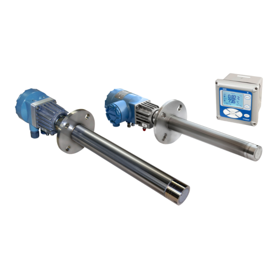
Emerson Rosemount 6888A Quick Start Manual
In situ oxygen analyzer
Hide thumbs
Also See for Rosemount 6888A:
- Reference manual (136 pages) ,
- Quick start manual (36 pages) ,
- Quick start manual (40 pages)

Related Manuals for Emerson Rosemount 6888A


Summary of Contents for Emerson Rosemount 6888A
- Page 1 Quick Start Guide 00825-0100-4890, Rev AC October 2022 ™ Rosemount 6888A In Situ Oxygen Analyzer...
- Page 2 Inform and educate your personnel in the proper installation, operation, and maintenance of the product. Follow appropriate local and national codes. If you do not understand any of the instructions, contact your Emerson representative for clarification. WARNING Explosions Do not open when an explosive atmosphere may be present.
-
Page 3: Table Of Contents
The Field Communicator must be upgraded to System Software 2.0 with graphic license for operation with the Rosemount 6888A Analyzer. The AMS software must be upgraded to AMS 8.0 or above. Contact Emerson's Global Service Center (GSC) at +1-800-833-8314 to upgrade the Field Communicator software to System Software 2.0 with graphic license. - Page 4 Quick Start Guide October 2022 Emerson.com/Rosemount...
-
Page 5: Installation
October 2022 Quick Start Guide Installation CAUTION Equipment damage If external loop power is used, the power supply must be a safety extra low voltage (SELV) type. Quick Start Guide... - Page 6 Do not install the analyzer in hazardous areas or in the vicinity of flammable liquids. Procedure 1. Ensure all components are available to install the probe. If using the optional ceramic or Hastelloy diffusion element, make sure to orient the vee deflector correctly. Emerson.com/Rosemount...
- Page 7 The through hole diameter in the stack or duct wall and refractory material must be at least 2.5 in (64 mm). NOTICE Emerson recommends an abrasion-resistant probe tube or traditional abrasive shield for high velocity particulates in the flue stream (such as those in coal -fired boilers, kilns, and recovery boilers).
- Page 8 Quick Start Guide October 2022 Figure 1-2: Rosemount 6888A probe with standard terminations/ electronic housing A. Dimension (see Table 1-1) B. Dimension (see Table 1-1) C. Standard tube D. Abrasion resistant tube Note All dimensions are in inches with millimeters in parentheses.
- Page 9 October 2022 Quick Start Guide Figure 1-3: Rosemount 6888A integral autocalibration housing A. Dimension (see Table 1-1) B. Hastelloy diffuser C. Ceramic diffuser D. Standard tube E. Abrasion tube F. Minimum removal length Note All dimensions are in inches with millimeters in parentheses.
- Page 10 Quick Start Guide October 2022 Figure 1-4: Rosemount 6888A integral autocalibration housing close-up A. Dimension (see Table 1-1) B. Reference air vents C. Calibration gas ¼-in tube fittings 5.0 scfh (2.4 L/min) 20 psig (1.38 barg) D. #10 socket head cap screw (external ground) E.
- Page 11 October 2022 Quick Start Guide Table 1-1: Insertion and removal dimensions (continued) Probe length Dimension A Dimension B Dimension B insertion depth removal envelope removal envelope standard housing accessory housing 9 ft (2.74 m) probe 104.52 in 118.6 in (3,012 mm) 122.1 in (3,101 mm) (2,654.8 mm) 12 ft (3.66 m) probe...
- Page 12 D. Equally spaced E. Four studs, lockwashers, and nuts equally spaced on C, diameter Note All dimensions are in inches with millimeters in parentheses. Table 1-2: Mounting flange ANSI Flange diameter 7.28 in (184.9 mm) Hole diameter 0.75 in (19.0 mm) Emerson.com/Rosemount...
- Page 13 October 2022 Quick Start Guide Table 1-2: Mounting flange (continued) ANSI (4) holes equally spaced 4.75 in (120.6 mm) 5.71 in (145.0 mm) on BC Table 1-3: Installation weld plate outline Dimension ANSI 152 in (3,861 mm) 191 in (4,851 mm) B thread 11 in (279 mm) M16x2...
- Page 14 B. Logic input/output, 4-20 mA signal C. Drip loop D. Stack or duct metal wall E. Adapter plate F. Insulation Note Replace insulation after installing analyzer. Note Standard housing probe shown. Accessory housing is similar. Probe installation may be vertical or horizontal. Emerson.com/Rosemount...
- Page 15 1.2.1 Wire Rosemount 6888A Analyzer probe only (no Rosemount 6888Xi Electronics) The Rosemount 6888A Analyzer probe has electronics in the blue housing that controls the heater temperature and also amplifies the raw O milli-volt signal to a linear 4-20 mA. You can run the 4-20 mA signal lines directly to the control room and also power the analyzer electronics.
- Page 16 L2/N terminal, and the ground wire to the ground lug. The analyzer accepts 120/240 Vac ±10 percent line voltage and 50/60 Hz. No setup is required. Figure 1-7: Rosemount 6888A standard probe housing A. AC input B. Ground C. Shield D.
- Page 17 The Rosemount 6888Xi Electronics serve as an operator interface unit with a back-lit display and keypad. It is capable of two channels, serving two Rosemount 6888A probes. Procedure 1. Remove cover screws from the front cover of the Rosemount 6888Xi.
- Page 18 Quick Start Guide October 2022 Figure 1-9: IO boards A. Rosemount 6888A standard probe housing B. IO board - channel 1 C. IO board - channel 2 D. AC input E. Ribbon cable to display board J2, Sensor 1 F. 4-20 mA output G.
- Page 19 October 2022 Quick Start Guide Table 1-4: Channel 1 jumper settings (continued) Jumpers Settings Pins 1-2, internal power Pins 2-3, external power Table 1-5: Channel 1 SW4 switch settings Position Setting Table 1-6: Channel 2 jumper settings Jumper Setting Pins 1-2 Pins 1-2 Pins 1-2, internal power Pins 2-3, external power...
- Page 20 October 2022 JP5: Pins 1-2 internal power Rosemount 6888Xi to Rosemount 6888A Analyzer, pins 2-3 external power Rosemount 6888Xi to Rosemount 6888A Analyzer (requires 2500 resistor across J4, PR+ to PR-) JP7/JP8: Pins 1-2 internal power Rosemount 6888Xi to DCS, pins 2-3 external power Rosemount 6888Xi to DCS.
- Page 21 October 2022 Quick Start Guide Figure 1-11: Rosemount 6888Xi bottom view A. AC input to power supply B. Plug C. Channel #2 alarm relay, Rosemount SPS D. Channel #2 4-20 mA/HART output E. Channel #1 alarm relay, Rosemount SPS F. Channel #1 4-20 mA/HART output 3.
- Page 22 2. Connect the line (L1 wire) to the L1 terminal, the neutral (L2) wire to the L2/N terminal, and the ground wire to the ground lug. The Rosemount 6888A accepts line voltage at 120/240 Vac ±10 percent, 50/60 Hz. No setup is required.
- Page 23 October 2022 Quick Start Guide 4. Terminate the shield at both the probe and the Rosemount 6888Xi Advanced Electronics. NOTICE The 4-20 mA signal represents the O value and also powers the probe-mounted electronics. Superimposed on the 4-20 mA signal is HART information accessible through a Field Communicator or Asset Management Solutions (AMS) software.
- Page 24 C. Ribbon cable to display board J2, Sensor 1 D. 4-20 mA HART output E. Test points F. Signal G. Ferrite clamp Table 1-9: IO board jumper settings Jumper Setting Pins 2-3 Pins 2-3 Pins 1-2, internal power Pins 2-3, external power Emerson.com/Rosemount...
- Page 25 October 2022 Quick Start Guide Table 1-9: IO board jumper settings (continued) Jumper Setting Pins 1-2, internal power Pins 2-3, external power Pins 1-2, internal power Pins 2-3, external power Figure 1-13: Analyzer probe field connections A. Test point group B.
- Page 26 FF segment. NOTICE The Rosemount 6888A probe is not rated as intrinsically safe (IS) and will render any IS or FISCO segment it is wired to as non-IS. Use a shielded twisted wire pair. Do not allow bare shield wires to contact the circuit boards.
- Page 27 October 2022 Quick Start Guide Rosemount 6888Xi. Use the following procedure to connect the traditional architecture probe to the Rosemount 6888Xi. NOTICE The traditional architecture cable is provided at the specified length and is ready for installation. The cable glands must be properly terminated to maintain EMC/electromagnetic interference (EMI) noise protection.
- Page 28 4. At the Rosemount 6888Xi, connect the cable leads to the connectors on the analyzer input/output (IO) board. Pneumatic installation 1.3.1 Reference air package After the Rosemount 6888A is installed, connect the reference air set to the analyzer unit. Refer to the schematic diagram in Figure 1-14 for a locally assembled reference air supply.
- Page 29 October 2022 Quick Start Guide Figure 1-14: Plant schematic diagram, standard housing A. Vent B. Calibration gas: ¼-in. tube C. To analyzer D. Reference air flow meter E. Instrument air supply: 10 psig (0.69 barg) to 80 psig (5.52 barg) pressure F.
- Page 30 E. Reference air flow meter F. Instrument air supply: 10 psig (0.69 barg) to 80 psig (5.52 barg) pressure G. ¼-in.-18 NPT female inlet connection H. ¼-in. or 6 mm O.D. tubing (supplied by customer) I. Reference gas: ¼-in. tube Emerson.com/Rosemount...
- Page 31 October 2022 Quick Start Guide Figure 1-16: Manual calibration panel Note Dimensions are in inches with millimeters in parentheses. Reference air components are included in the optional manual calibration panel (Figure 1-16) and the Rosemount SPS 4001 Single Probe Autocalibration Sequencer. Quick Start Guide...
- Page 32 Do not use gases with hydrocarbon concentrations of more than 40 parts per million. CAUTION Before washing down the ducts, verify that the Rosemount 6888A Analyzers have been powered down and removed from the wash areas. CAUTION Damage can result from having a cold analyzer exposed to process gases.
- Page 33 October 2022 Quick Start Guide Figure 1-17: Calibration gas connections A. Calibration gas in B. Reference air vent C. Reference air in Figure 1-18: Traditional architecture cable gland assembly Quick Start Guide...
-
Page 34: Configuration, Start-Up, And Operation
4-20 mA output is based on the default range of 0 to 10 percent O If there is an error condition at start-up, an alarm message is displayed. Power up the Rosemount 6888A direct replacement probe (no electronics inside) with traditional architecture... - Page 35 October 2022 Quick Start Guide The analyzer probe takes approximately 45 minutes to warm up to the 1,357 °F (736 °C) heater set point. The 4-20 mA signal remains at a default value of 3.5 mA, and the O reading remains at 0 percent through this warm- up period.
- Page 36 Calibration 2.4.1 Manual/semi-automatic calibration A technician can calibrate the Rosemount 6888A probe with standard housing by following prompts via the display of the Rosemount 6888Xi ® Electronics or via HART communications to a Field Communicator or Asset Management Solutions (AMS) console.
- Page 37 October 2022 Quick Start Guide NOTICE A loose or missing cap can permit fresh air to bias the O readings high in processes that run at negative pressure. Make sure the calibration gas port is capped tightly between calibrations. 2.4.2 Fully automatic calibration For fully automatic calibration, the Rosemount 6888Xi Electronics must manage the actuation of solenoids to introduce gases into the probe.
- Page 38 1. Use the Field Communicator to access the main HART menu. 2. From the main menu, select CONFIGURE. 3. From the CONFIGURE menu, select CALIBRATION. 4. From the CALIBRATION menu, again select CALIBRATION. 5. From the CALIBRATION menu, select O CALIBRATION. Emerson.com/Rosemount...
- Page 39 In the first screen, a Loop should be removed from warning occurs. automatic control 6. Remove the Rosemount 6888A from any automatic loop controls to avoid a potentially dangerous operating condition. Press OK when ready. 7. At the next screen, when the step shows...
- Page 40 Press the Left key to return to the ALERTS menu. f) From the ALERTS menu, select DEVICE STATUS. g) From the DEVICE STATUS menu, select ACKNOWLEDGE. h) From the ACKNOWLEDGE menu, select ACK CALIBRATION FAILED. When the process is complete, the system returns to the ACKNOWLEDGE menu. Emerson.com/Rosemount...
-
Page 41: Product Certifications
(CEC) permit the use of Division marked equipment in Zones and Zone marked equipment in Divisions. The markings must be suitable for the area classification, gas, and temperature class. This information is clearly defined in the respective codes. Rosemount 6888A In Situ Oxygen Analyzer for general purpose locations 3.4.1 USA/Canada... - Page 42 Quick Start Guide October 2022 • 90 °C for Rosemount 6888A DR Probe 4. Mounting flange temperature shall not exceed 200 °C. 3.4.2 Europe TUVRheinland QAL1 0000038506 Certificate Standards EN15267-1:2009, EN15627-2:2009, EN15627-3:2007, EN14181:2004 MCERTS Certificate Sira MC140270/03 Standards EN15267-1:2009, EN15627-2:2009,...
- Page 43 October 2022 Quick Start Guide Rosemount SPS4001B and Rosemount IMPS4000 Autocalibration Devices for general purpose locations 3.6.1 USA/Canada CSA certificate 80052172 Standards CAN/CSA C22.2 No. 61010-1-04; ANSI/UL 61010-1:2004, (2nd edition); CSA C22.2 No. 94.2 (1st edition); ANSI/UL 50 E (1st edition); CSA C22.2 No. 60529:05 (R2010); ANSI/IEC 60529-2004 (R2011) Markings Type 4X, IP66...
-
Page 44: Declaration Of Conformity
Quick Start Guide October 2022 Declaration of Conformity Emerson.com/Rosemount... - Page 45 October 2022 Quick Start Guide Quick Start Guide...
-
Page 46: China Rohs Table
Quick Start Guide October 2022 China RoHS table Emerson.com/Rosemount... - Page 47 October 2022 Quick Start Guide Quick Start Guide...
- Page 48 For more information: Emerson.com © 2022 Emerson. All rights reserved. Emerson Terms and Conditions of Sale are available upon request. The Emerson logo is a trademark and service mark of Emerson Electric Co. Rosemount is a mark of one of the Emerson family of companies.
Need help?
Do you have a question about the Rosemount 6888A and is the answer not in the manual?
Questions and answers