Table of Contents

Related Manuals for FULTON Endura XE


Summary of Contents for FULTON Endura XE
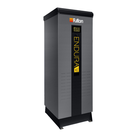
- Page 1 INSTALLATION, OPERATION AND MAINTENANCE MANUAL Endura XE (EXE) Condensing Hydronic Boilers 399,000 - 750,000 BTU/HR Featuring PURE Control™ Serial/ National Board Number Model Fulton Order Owner Site Name Date EXE-IOM-230112...
-
Page 3: Table Of Contents
SIDE WALL VENT TERMINATION ....................2-27 Removing an Existing Boiler ................2-31 Removing and Cleaning Burner Assembly ............4-6 Assembly of Fulton Multi-Skid Systems............. 2-31 Removing and Cleaning Flame Rod ..............4-7 Electrical Connections and Devices ..............2-32 Verification of Ignition Electrode Gap ..............4-8 After All Repairs and Maintenance .............. -
Page 5: Introduction 1-1 Operation
INTRODUCTION INTRODUCTION INSTALLATION OPERATION MAINTENANCE SERVICE DOCUMENTS Questions? Please Contact Your Local Manufacturer’s Representative... -
Page 6: Overview
Code ANSI Z223.1/NFPA 54 latest edition, and the specific should it replace existing codes or standards which may be instructions in this manual. Authorities having jurisdiction applicable. Fulton reserves the right to change any part of should be consulted prior to installation. this installation, operation and maintenance manual. -
Page 7: Installation
INSTALLATION INTRODUCTION INSTALLATION OPERATION MAINTENANCE SERVICE DOCUMENTS Questions? Please Contact Your Local Manufacturer’s Representative... - Page 8 The Fulton Endura XE hot water boiler is an automatic, fuel-fired, ultra high- jurisdictional/professional codes and efficiency boiler. Combustion air supply may be ducted to the boiler from the regulations.
- Page 9 Placement & Rigging WARNING All information in this manual is for Proper placement of your Fulton product is essential. Attention paid to reference and guidance purposes, the following points will save a great deal of difficulty in the future. Correct...
- Page 10 M. Sides NOTES: May be operated up to 10,000 feet elevation, and up to 1,000 feet elevation at 80˚ F without de-rate. Consult your Fulton Representative for capacities at higher elevation. 2Applies to natural gas with a calorific value of 1,010 BTU per FT3.
-
Page 11: Clearances And Serviceability
INSTALLATION SECTION 2 EXE-IOM-230112 Clearances and Serviceability 3. The discharge pipe must: » Not have a diameter less than the full area of Adhere to the following for clearances and serviceability: the valve outlet. » Be as short and straight as possible and so 1. -
Page 12: Install Water Piping
ƒ A drain valve is recommended (not provided) on the boiler inlet piping. ƒ Boiler connection dimensions are for reference and not for construction purposes. Pre-fabricating boiler piping is not recommended. © Fulton Group N.A., Inc. 2023... - Page 13 INSTALLATION SECTION 2 EXE-IOM-230112 WARNING ƒ Install filtration in the common loop or per boiler to remove particulates if appropriate. A #4 or finer mesh size is required. All information in this manual is for ƒ Install bypass chemical feeder for corrosion inhibitor maintenance if reference and guidance purposes, appropriate.
- Page 14 Note: Sample piping layout (P&ID) is a general representation of system installation. Good practice should be used in system design, including but not limited to adequate pipe/valve sizing and natural flow path for system water. © Fulton Group N.A., Inc. 2023...
- Page 15 INSTALLATION SECTION 2 EXE-IOM-230112 HEATING HOT ENDURA XE SERIES AIR REMOVAL WATER SUPPLY CONDENSING BOILER SUPPLY WATER TEMPERATURE SENSOR NOTE: INSTALL 5 TO 10 PIPE DIAMETERS DOWNSTREAM OF CLOSELY SPACED TEES SYSTEM (SECONDARY) PUMP(S) CLOSELY SPACED TEES NOTE: ≤ 4 DIAMETERS...
- Page 16 (system) piping. Do not use separate connections for each boiler into the secondary piping. » Use a reverse return primary header to balance flow across the boilers. Where reverse return cannot be used, it is recommended to install a balancing valve per boiler. 2-10 © Fulton Group N.A., Inc. 2023...
-
Page 17: Meet Water Chemistry Requirements
INSTALLATION SECTION 2 EXE-IOM-230112 Meet Water Chemistry Requirements WARNING All information in this manual is for reference and guidance purposes, System water chemistry requirements are as follows: and does not substitute for required ƒ pH: Range of 8.5 - 10.5 professional training, conduct, and strict adherence to applicable ƒ... -
Page 18: Fill The Boiler With Water
6. When the boiler is installed at a higher level than baseboard radiation (if used), air elimination must be provided directly above the unit. MEASURE INLET (SUPPLY) GAS PRESSURE HERE FIGURE 8 - MEASURING INLET GAS PRESSURE 2-12 © Fulton Group N.A., Inc. 2023... - Page 19 INSTALLATION SECTION 2 EXE-IOM-230112 Measure at the location shown in Figure 8 and adhere to the following: Static inlet gas pressure: Measure while boiler is idle. Verify pressure is ƒ within allowable range. Dynamic inlet gas pressure: Measure while boiler is in operation at ƒ...
- Page 20 8. The boiler gas train must be disconnected at the boiler manual shutoff valve from the gas supply piping system during any pressure testing of the system at pressures in excess of 0.5 psig (14 inch W.C.). 2-14 © Fulton Group N.A., Inc. 2023...
- Page 21 INSTALLATION SECTION 2 EXE-IOM-230112 TABLE 3 - SCH 40 PIPE NATURAL GAS CAPACITY Nominal Equivalent Pipe Length Max Capacity in ft3 of natural gas per hour. 14”wc pressure. Pipe Size Pressure drop of 0.5”wc. Equivalent length of pipe (feet) Inch (mm) Inch (mm) 90 Elb Feet...
-
Page 22: Temperature
4. THE FLUE GAS CONDENSATE TRAP MUST BE LOWER THAN THE CONDENSATE DRAIN OUTLET OF THE BOILER. 5. ONE (1) FLUE GAS CONDENSATE TRAP MUST BE INSTALLED PER EACH BOILER, DO NOT MANIFOLD DRAIN LINES. FIGURE 10 - CONDENSATE DRAIN PIPING 2-16 © Fulton Group N.A., Inc. 2023... - Page 23 1. Use PVC, CPVC, stainless steel, or silicone tube and fittings to connect condensate trap to the neutralizer. – NOTE: Replacement medium is available from your Fulton local representative. NOTES: 1. A PH NEUTRALIZER IS USED TO RAISE THE PH OF THE ACIDIC FLUE GAS CONDENSATE PRIOR TO DISPOSAL INTO THE FLOOR DRAIN.
- Page 24 Combustion air intake piping (if used) must be accounted for in an analysis of the venting system. 2-18 © Fulton Group N.A., Inc. 2023...
-
Page 25: Combustion Air Intake
Ensure there is not a negative pressure in the 7. Site specific conditions not addressed in this manual may require boiler room. The boiler room pressure must additional precautions or design considerations. Consult your local Fulton be neutral relative to the outdoors. Representative and venting supplier for recommendations. - Page 26 12 inches of the ceiling, and a low opening commences within 12 inches of the floor. See Table 6. 5. For installations providing a single permanent opening directly communicating with the outdoors, the minimum net free area of the 2-20 © Fulton Group N.A., Inc. 2023...
- Page 27 INSTALLATION SECTION 2 EXE-IOM-230112 WARNING opening is 1 in2 per 3,000 BTU/hr of the total input capacity of the combined burners located in the boiler room. See Table 6. All information in this manual is for reference and guidance purposes, 6.
-
Page 28: Flue Gas Exhaust Venting
Table 6, and a spill switch and a Carbon Monoxide detector are installed and interlocked with the boiler(s). Barometric dampers must never be used in a positive pressure (Category IV) exhaust or ducted combustion air application. 2-22 © Fulton Group N.A., Inc. 2023... -
Page 29: Common Flue Gas Venting Layouts
6. A stainless steel adapter (not supplied) specific to vent manufacturer type and material will be required. Refer to Table 7 or consult the venting Fulton accepts no liability for installation supplier for guidance. of any venting, including the selection of venting materials. - Page 30 SIZED FOR A SLIGHT NEGATIVE DRAFT PRESSURE UP TOWARDS TERMINATION (DO NOT USE STATIC REGAIN METHOD) SWEEPING 90° ELBOW 45° REDUCING TEE POINTING IN THE DIRECTION OF FLOW FIGURE 12 - COMMON EXHAUST VENTING; TYPICAL INSTALLATION GUIDELINES 2-24 © Fulton Group N.A., Inc. 2023...
- Page 31 WARNING 2. This boiler is not approved for common venting with other equipment, such as steam boilers, water heaters, generators, and other types of Fulton accepts no liability for installation equipment. of any venting, including the selection of venting materials. Maximum allowable 3.
- Page 32 SECTION 2 EXE-IOM-230112 WARNING Venting Terminations Fulton accepts no liability for installation of any venting, including the selection of Adhere to National Fuel Gas Code (ANSI Z223.1) and the following for installation: venting materials. Maximum allowable flue gas operating temperatures may 1.
- Page 33 INSTALLATION SECTION 2 EXE-IOM-230112 SCREW OR BOLT EACH THIMBLE COLLAR TO WALL ƒ Side Wall Vent Termination (TYPICAL 4 PLACES) ORIENT CLAMPS AND COLLAR AS REQUIRED PIPE RETAINING CLAMP, TYPICAL Adhere to the following for installation (see Figure 16): EACH SIDE END VIEW NOTE: The vent termination is joined to the vent pipe outside...
- Page 34 DIRECTION OF FLOW AIR INTAKE RUBBER COUPLING (INCREASER REQUIRED FOR 650/750) UL-1738 LISTED AND LABELED SPECIAL GAS VENT APPLIANCE ADAPTER CONSULT FLUE MFG FOR SELECTION LEVEL HOUSEKEEPING PAD FIGURE 14 - ROOF PENETRATION DETAILS 2-28 © Fulton Group N.A., Inc. 2023...
- Page 35 INSTALLATION SECTION 2 EXE-IOM-230112 TYPICAL ROOF PENETRATION FLUE GAS EXHAUST TERMINATION (RAIN CAP NOT RECOMMENDED) COMBUSTION AIR FROM THE ROOM ( SUGGESTED INSTALLATION CONFIGURATIONS ) STORM COLLAR (FOR DOUBLE WALL) NOTES: 1) HORIZONTAL SECTIONS MUST ADHERE TO A MINIMUM 1/4 INCH PER FOOT (1 MM PER 48 MM) RISE TO RUN RATIO 2) MAINTAIN A MINIMUM 9 INCH (229 MM) AIR SPACE CLEARANCE TO COMBUSTABLES, WIRE, AND INSULATION 3) INSTALL SUPPORT STRAPS AT 5 FT (152 CM) HORIZONTAL...
- Page 36 FLUE GAS EXHAUST 1/2 INCH x 1/2 INCH DIRECTION OF FLOW (13 MM x 13 MM) MESH SCREEN APPLIANCE ADAPTER CONSULT FLUE MFG FOR SELECTION LEVEL HOUSEKEEPING PAD FIGURE 16 - SIDEWALL PENETRATIONS DETAILS 2-30 © Fulton Group N.A., Inc. 2023...
- Page 37 When an existing boiler is removed from a common venting Adhere to the following for multi-skid engineered systems: system, the common venting system is likely to be too large for 1. Refer to the Fulton mechanical/electrical drawings proper venting of the appliances remaining connected to it. during assembly.
- Page 38 The boiler’s cabinet features removable panels to facilitate wires are labeled for easy landing. Connect all wiring maintenance access. Do not run conduit through or over per the Fulton supplied electrical drawings. these access panels. 9. If a header sensor is supplied, mount the header sensor Adhere to the following when making electrical connections: as shown in the mechanical drawing.
- Page 39 INSTALLATION SECTION 2 EXE-IOM-230112 FIGURE 17 - ELECTRICAL SCHEMATIC DIAGRAM (REFERENCE ONLY) 2-33 Questions? Please Contact Your Local Manufacturer’s Representative...
- Page 40 BLOWER MOTOR POWER (BM) (H) CONTROL FAN (CF) (N) CONTROL FAN (CF) MAIN VALVE 2 (MV2) FLAME ROD IGNITION GROUND (H) BIMETAL BLOCKED INTAKE SWITCH (BIS) FIGURE 17 (CONTINUED) - ELECTRICAL SCHEMATIC DIAGRAM (REFERENCE ONLY) 2-34 © Fulton Group N.A., Inc. 2023...
- Page 41 INSTALLATION SECTION 2 EXE-IOM-230112 BARRIER STRIP 1 BARRIER STRIP 2 POS + REMOTE TEMP. 4-20mA REMOTE BOILER ENABLE 24VDC 6mA SIGNAL SETPOINT INPUT CONTACT CLOSURE (REMOVE JUMPER) NEG - POS + 2ND (AUX) LWCO PROBE 4-20mA OUTPUT NEG - BOILER PUMP MODULATION OUTDOOR AIR 10K THERMISTOR BOILER INTERLOCK...
- Page 42 INSTALLATION SECTION 2 EXE-IOM-230112 FUSING 24VAC TRANSFORMER FLAME SAFEGUARD 24VDC POWER SUPPLY 5VDC POWER SUPPLY LOW WATER RELAY AUXILIARY MOTOR LOW WATER CONTROLLERS (OPTIONAL) FIELD CONNECTIONS FIGURE 19 - ELECTRICAL CONTROLS LAYOUT 2-36 © Fulton Group N.A., Inc. 2023...
- Page 43 NEMA 1-15 plug, this device is intended for field installation in a clean dry area such as a 1. The Fulton PURE Control™ includes integrated networking closet, rack, or panel enclosure. For sequencing capabilities. When utilized, the boiler...
- Page 44 Ensure connections are tight with no shorts. Soldered hot water storage tank. and heat shrink tubing connections are recommended. Never use wire nuts to join lead to extension. 2-38 © Fulton Group N.A., Inc. 2023...
- Page 45 INSTALLATION SECTION 2 EXE-IOM-230112 3. See the Operation section for programming DHW applications requiring a safety interlock, this jumper priority. Refer to the Hydronic PURE Control™ User may be removed with terminals wired into the dry Manual for complete instructions. contacts of an external device.
- Page 46 ` GENERAL ALARM CONTACT A dry contact is provided for annunciation of a general alarm condition. It is rated for maximum 0.6 Amps at 24 VAC only. 2-40 © Fulton Group N.A., Inc. 2023...
- Page 47 OPERATION INTRODUCTION INSTALLATION OPERATION MAINTENANCE SERVICE DOCUMENTS Questions? Please Contact Your Local Manufacturer’s Representative...
- Page 48 6. Check temperature/pressure indicator reading, which should equal the pressure-reducing (fill) valve set pressure. No more water should be entering the system. Close the shutoff valve on the cold-water fill line. © Fulton Group N.A., Inc. 2023...
- Page 49 3. Performance factors affected may include but are not limited to input/ output ratings, efficiency, modulation rates and emissions. 4. The Fulton factory Test Fire Report should be used as a point of reference in commissioning settings for the boilers in the field, however a factory certified service technician should account for all site conditions when finalizing operational settings.
- Page 50 Configuration and verify the software version is up to date. If a newer version of the software is available, update before continuing. Refer to the Endura XE™ PURE Control™ User Manual for instruction. 7. Navigate to Tech Tools and then to the Commissioning screen.
- Page 51 OPERATION SECTION 3 EXE-IOM-230112 WARNING All information in this manual is for reference and guidance purposes, and does not substitute for required professional training, conduct, and strict adherence to applicable jurisdictional/ COMBUSTION ANALYSIS professional codes and regulations. TEST PORT LOCATION Tampering with safety devices or unauthorized bypassing of the boiler NOTE: INSERT ANALYZER...
- Page 52 Downstream are only made at P10. 15. Carefully check for gas leaks along the field gas piping, factory gas train, pre-mix system (blower discharge region) and exhaust collection and disposal systems. A GAS-Mate® 0119 combustible gas detector or © Fulton Group N.A., Inc. 2023...
- Page 53 Test Fire Report or factory provided combustion parameters. Fan Position must have a minimum separation of 100 RPM between points. Non-Fulton product information is for Do not adjust MV Downstream at P0-P9. reference purposes only. No Fulton document should substitute for full review 17.
- Page 54 8. For new equipment start-up, warranty coverage is valid only if the I&O Non-Fulton product information is for form is successfully completed and returned to the Fulton factory service reference purposes only. No Fulton coordinator within twelve weeks of start-up.
- Page 55 The graphical interface is navigated by touch using your finger or a stylus. The screenshots and information in this section will guide you through the menu screens. Non-Fulton product information is for reference purposes only. No Fulton document should substitute for full review ƒ...
- Page 56 ` STATUS Non-Fulton product information is for reference purposes only. No Fulton Summarizes detailed operating information and sensor status for the boiler. document may substitute for full review of documentation available from the component manufacturer.
- Page 57 The secondary (system) pump contact is closed at all times while the boiler plant Non-Fulton product information is for is enabled and allowed to run, even while no burners are operating. This contact reference purposes only. No Fulton opens upon the prescribed delay settings.
- Page 58 (primary) pump is enabled in a primary secondary piping system. When the boiler vessel water temperature falls below a configured temperature, the boiler (primary) pump will be enabled until the set temperature has been reached. 3-12 © Fulton Group N.A., Inc. 2023...
- Page 59 The Soft Limit acts to prevent nuisance manual reset high limit trips. If the boiler outlet temperature exceeds the soft limit, the burner will be driven to low fire Non-Fulton product information is for until the outlet temperature is reduced to the value assigned in the Soft Limit reference purposes only.
- Page 60 An administrator password can be assigned to the control to prevent unauthorized access. The selected screens will require entry of the administrator password prior to access. The password may be up to 10 characters in length. 3-14 © Fulton Group N.A., Inc. 2023...
- Page 61 1. Alter high temperature limit to a value lower than the anticipated loop temperature. Turn the boiler on. Water temperature will rise until the Non-Fulton product information is for boiler locks out. This condition has to be manually reset. reference purposes only. No Fulton 2.
- Page 62 OPERATION SECTION 3 EXE-IOM-230112 PAGE INTENTIONALLY LEFT BLANK 3-16 © Fulton Group N.A., Inc. 2023...
- Page 63 MAINTENANCE INTRODUCTION INSTALLATION OPERATION MAINTENANCE SERVICE DOCUMENTS Questions? Please Contact Your Local Manufacturer’s Representative...
- Page 64 CAUTION All maintenance procedures should be completed by trained personnel. Appropriate training and instructions are available from the Fulton Service Department at (315) 298-5121 or your local Fulton Heating Solutions Representative. In order to meet warranty conditions, ensure all appropriate maintenance activities are performed.
-
Page 65: Tool List
MAINTENANCE SECTION 4 EXE-IOM-230112 Tool List WARNING All information in this manual is for To complete routine preventative maintenance or repairs, certain tools and reference and guidance purposes, supplies will be required that are not provided with the boiler. The qualified and does not substitute for required service technician should be prepared with the following tools and supplies. -
Page 66: Daily Inspection Schedule
Consult Fulton Heating Solutions immediately if there is a concern. 4. Test low gas pressure switch and high gas pressure switch utilizing the Using nuts and washers not provided procedure in Operation section of this manual. -
Page 67: Annual Maintenance Schedule
Annual maintenance must be completed and properly documented by a factory reference and guidance purposes, authorized technician holding a valid Endura XE Certificate of Registration and does not substitute for required to maintain warranty coverage. Schedule your annual maintenance to be... -
Page 68: Removing And Cleaning Burner Assembly
NOTE: Due to unique hardware specifications, alternate hardware must not be – jurisdictional/professional codes and substituted. If hardware is lost or damaged, contact your Fulton representative for regulations. replacement. All maintenance procedures should 6. Remove blower discharge transition. -
Page 69: Removing And Cleaning Flame Rod
MAINTENANCE SECTION 4 EXE-IOM-230112 Removing and Cleaning Flame Rod WARNING All information in this manual is for This boiler uses an ionization electrode flame rod for proof of burner flame reference and guidance purposes, during light-off and normal run. Replacement of the flame rod is part of the and does not substitute for required annual maintenance. -
Page 70: Verification Of Ignition Electrode Gap
1. Remove ignition electrode assembly (ignitor). Visually check that the insulators are clean. Using nuts and washers not provided by Fulton can lead to flue gas leakage 2. For re-installation or installation of a new ignitor, verify with calibrated and cause damage to the studs. -
Page 71: After All Repairs And Maintenance
MAINTENANCE SECTION 4 EXE-IOM-230112 WARNING 6. Position a light to shine into the combustion chamber through the sight glass. All information in this manual is for 7. Visually verify the ignition position relative to the burner head: reference and guidance purposes, and does not substitute for required ƒ... -
Page 72: Parts Diagrams
.59" TO 1.00" X 1" CONDUIT NYLON STRAIN RELIEF 7-53-420001-42 CABINET FAN ASSEMBLY *PARTS VARY BETWEEN XE 399/500 & XE 650/750. REFER TO BOILER SIZING FOR CORRECT PART NUMBERS. FIGURE 26 - CABINET (EXE-399 TO 750) 4-10 © Fulton Group N.A., Inc. 2023... - Page 73 MAINTENANCE SECTION 4 EXE-IOM-230112 PART NUMBER DESCRIPTION 2-12-000721 SPARK IGNITION/FLAME ROD O-RING 2-12-420001-42 SIGHT GLASS TO FLAME ROD O-RING 2-12-420002-42 SIGHT GLASS 2-12-420015-42 BURNER TO SIGHT GLASS GASKET 2-20-420000-42 FLAME ROD 2-20-420001-42 SPARK IGNITION ASSEMBLY 2-22-420008 M4-.7 X 8mm SS FLANGED BHCS 2-22-420027 18-8 STAINLESS STEEL SLOTTED SPRING PIN 2-35-000010...
- Page 74 GAS REGULATOR 5-10-420037-42 1" MEDIUM PORT BUTTERFLY VALVE W/ STEPPER MOTOR ASSEMBLY 7-53-420000-42 GAS VALVE NOTE: GAS PRESSURE SWITCHES NOT USED ON UNITS WITHOUT CSD-1 COMPLIANCE FIGURE 28 - GAS TRAIN (EXE-399 TO 750) 4-12 © Fulton Group N.A., Inc. 2023...
- Page 75 PART NUMBER DESCRIPTION ITEM PART NUMBER DESCRIPTION 2-45-315111 5VDC POWER SUPPLY 2-40-420010-42 STEPPER MOTOR DRIVER BOARD 2-40-000421 FULTON HI/LO WATER RELAY 2-45-000440 TERMINAL BLOCK 2-45-000371 FUSE HOLDER 2-45-000607 2 POLE JUMPER 2-45-001078 2 TIER TERMINAL BLOCK 2-45-000580 CLASS J FUSEBLOCK COVER...
- Page 76 EDR XE 399/500 BURNER PLATE 5-10-420025-42 PBA TO BLOWER ADAPTER PLATE 5-10-420041-42 PBA ASSEMBLY 5-10-420044-42 AIR SWITCH BRACKET 5-10-420505-42 EXE 399/500 PREMIX CAP ASSEMBLY 5-21-420009-42 AIR INTAKE ADAPTER ASSEMBLY FIGURE 30 - BURNER AND PRE-MIX ASSEMBLY (EXE-399/500) 4-14 © Fulton Group N.A., Inc. 2023...
- Page 77 MAINTENANCE SECTION 4 EXE-IOM-230112 ITEM PART NUMBER DESCRIPTION 2-12-000286 5/8" SQUARE ROPE GASKET 2-12-315004 FLEXIBLE TUBING 2-12-420000 BLOWER TO PRE-MIX O-RING 2-12-420004 AIR INTAKE TO PBA O-RING 2-22-000026 6-32 X 1/2" PAN HEAD T/S F PHILLIPS HEAD SCREW 2-22-000177 6-32 LOCK NUT 2-22-420001 M8-1.25 X 16mm ZINC PLATED SERRATED FLANGE BOLT 2-22-420002...
-
Page 78: Troubleshooting
If calibrated flow meters are not available, flow rate can be approximated by calculation by observing the delta-T across the boiler heat exchanger at a given firing rate. See the Fulton “Calculating Flow Rate” Engineering Guide for more details. Boiler Excessively Cycling... - Page 79 MAINTENANCE SECTION 4 EXE-IOM-230112 PROBLEM CAUSE CHECK Main Flame Failure Maintenance Verify combustion parameters at all combustion points. Adjust as necessary. Verify sufficient supply gas pressure within the requirements of the data plate at the rear of the boiler. Ensure gas pressure does not drop more than 15% between static (idle) and dynamic (high fire).
- Page 80 If a “Version Mismatch: UniLogic/UniStream Firmware" screen is prompted while performing the program update, continue performing the update as outlined in Section 4 of the PURE Controls Addendum. If further issues are experienced, contact Fulton technical support No SD Card Error Controller/Settings Install/Replace microSD card with a capacity of 4GB or larger.
-
Page 81: Service
SERVICE DOCUMENTS INTRODUCTION INSTALLATION OPERATION MAINTENANCE SERVICE DOCUMENTS Questions? Please Contact Your Local Manufacturer’s Representative... - Page 82 SERVICE DOCUMENTS SECTION 5 EXE-IOM-230112 PAGE INTENTIONALLY LEFT BLANK © Fulton Group N.A., Inc. 2023...
-
Page 83: Pre-Commissioning Installation Checklist
Gas regulators installed minimum 10 feet of pipe from the boilers? SITE SIGN-OFF DATE: PRINT NAME TITLE: When complete, return a copy to your Fulton Representative and/or the service organization performing commissioning (“start-up”) services. Questions? Please Contact Your Local Manufacturer’s Representative... - Page 84 SERVICE DOCUMENTS SECTION 5 EXE-IOM-230112 PAGE INTENTIONALLY LEFT BLANK © Fulton Group N.A., Inc. 2023...
-
Page 85: Installation & Operation "Start-Up" Report
NOTE: TO BE COMPLETED BY A FACTORY AUTHORIZED TECHNICIAN HOLDING A VALID ENDURA XE CERTIFICATE OF REGISTRATION. WARRANTY COVERAGE IS VALID ONLY IF THIS FORM IS SUCCESSFULLY COMPLETED AND RETURNED TO FULTON WITHIN TWELVE WEEKS OF START-UP. DATE FULTON REP. - Page 86 Manometer or equivalent. The use of a digital manometer is not recommended. When complete, please keep this form with the boiler, store a record copy in a safe location, and return a copy to Fulton: When complete, please keep this form with the boiler, store a record copy in a safe location, and return a copy to Fulton:...
-
Page 87: Annual Maintenance Checklists
SERVICE DOCUMENTS SECTION 5 EXE-IOM-230112 ANNUAL MAINTENANCE CHECKLIST NOTE: TO BE COMPLETED BY A FACTORY AUTHORIZED TECHNICIAN HOLDING A VALID ENDURA XE CERTIFICATE OF REGISTRATION. DATE TECH CERTIFICATE # TECHNICIAN BOILER MODEL TECH. COMPANY BOILER NB/SERIAL # ANNUAL MAINTENANCE: Burner head removed and visually inspected... - Page 88 Installation, Operation, and Maintenance Manual must be produced for warranty consideration. Please use photocopies or consult your local Fulton Representative for additional copies of this form. 2022-1010-EXE-MX-FORM © Fulton Group N.A., Inc. 2023...
- Page 89 SERVICE DOCUMENTS SECTION 5 EXE-IOM-230112 ANNUAL MAINTENANCE CHECKLIST NOTE: TO BE COMPLETED BY A FACTORY AUTHORIZED TECHNICIAN HOLDING A VALID ENDURA XE CERTIFICATE OF REGISTRATION. DATE TECH CERTIFICATE # TECHNICIAN BOILER MODEL TECH. COMPANY BOILER NB/SERIAL # ANNUAL MAINTENANCE: Burner head removed and visually inspected...
- Page 90 When complete, please keep this form with the boiler and store a record copy in a safe location. Accurate and complete combustion and maintenance records detailing compliance with the Installation, Operation, and Maintenance Manual must be produced for warranty consideration. Please use photocopies or consult your local Fulton Representative for additional copies of this form. 2022-1010-EXE-MX-FORM 5-10...
- Page 91 SERVICE DOCUMENTS SECTION 5 EXE-IOM-230112 ANNUAL MAINTENANCE CHECKLIST NOTE: TO BE COMPLETED BY A FACTORY AUTHORIZED TECHNICIAN HOLDING A VALID ENDURA XE CERTIFICATE OF REGISTRATION. DATE TECH CERTIFICATE # TECHNICIAN BOILER MODEL TECH. COMPANY BOILER NB/SERIAL # ANNUAL MAINTENANCE: Burner head removed and visually inspected...
- Page 92 When complete, please keep this form with the boiler and store a record copy in a safe location. Accurate and complete combustion and maintenance records detailing compliance with the Installation, Operation, and Maintenance Manual must be produced for warranty consideration. Please use photocopies or consult your local Fulton Representative for additional copies of this form. 2022-1010-EXE-MX-FORM 5-12...
- Page 93 SERVICE DOCUMENTS SECTION 5 EXE-IOM-230112 ANNUAL MAINTENANCE CHECKLIST NOTE: TO BE COMPLETED BY A FACTORY AUTHORIZED TECHNICIAN HOLDING A VALID ENDURA XE CERTIFICATE OF REGISTRATION. DATE TECH CERTIFICATE # TECHNICIAN BOILER MODEL TECH. COMPANY BOILER NB/SERIAL # ANNUAL MAINTENANCE: Burner head removed and visually inspected...
- Page 94 When complete, please keep this form with the boiler and store a record copy in a safe location. Accurate and complete combustion and maintenance records detailing compliance with the Installation, Operation, and Maintenance Manual must be produced for warranty consideration. Please use photocopies or consult your local Fulton Representative for additional copies of this form. 2022-1010-EXE-MX-FORM 5-14...
- Page 95 SERVICE DOCUMENTS SECTION 5 EXE-IOM-230112 ANNUAL MAINTENANCE CHECKLIST NOTE: TO BE COMPLETED BY A FACTORY AUTHORIZED TECHNICIAN HOLDING A VALID ENDURA XE CERTIFICATE OF REGISTRATION. DATE TECH CERTIFICATE # TECHNICIAN BOILER MODEL TECH. COMPANY BOILER NB/SERIAL # ANNUAL MAINTENANCE: Burner head removed and visually inspected...
- Page 96 When complete, please keep this form with the boiler and store a record copy in a safe location. Accurate and complete combustion and maintenance records detailing compliance with the Installation, Operation, and Maintenance Manual must be produced for warranty consideration. Please use photocopies or consult your local Fulton Representative for additional copies of this form. 2022-1010-EXE-MX-FORM 5-16...
-
Page 97: Notes
SERVICE DOCUMENTS SECTION 5 EXE-IOM-230112 NOTES 5-17 Questions? Please Contact Your Local Manufacturer’s Representative... - Page 98 SERVICE DOCUMENTS SECTION 5 EXE-IOM-230112 NOTES 5-18 © Fulton Group N.A., Inc. 2023...
- Page 99 SERVICE DOCUMENTS SECTION 5 EXE-IOM-230112 NOTES 5-19 Questions? Please Contact Your Local Manufacturer’s Representative...
- Page 100 Fulton Group N.A., Inc. Fulton Steam Solutions, Inc., Fulton Heating Solutions, Inc. & Fulton Thermal Corporation are part of Fulton Group N.A., Inc., a global manufacturer of steam, hot water and thermal fluid heat transfer systems.
Need help?
Do you have a question about the Endura XE and is the answer not in the manual?
Questions and answers