Advertisement
Quick Links
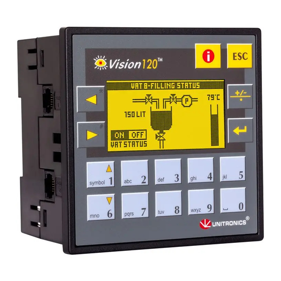
Vision V120™ , M91™ PLC
General Description
The products listed above are micro-PLC+HMIs, rugged programmable logic controllers that comprise
built-in operating panels.
Detailed Installation Guides containing the I/O wiring diagrams for these models, technical specifications,
and additional documentation are located in the Technical Library in the Unitronics website:
https://unitronicsplc.com/support-technical-library/
Alert Symbols and General Restrictions
When any of the following symbols appear, read the associated information carefully.
Symbol
Meaning
Danger
Warning
Caution
Caution
▪ Before using this product, the user must read and understand this document.
▪ All examples and diagrams are intended to aid understanding, and do not guarantee operation.
Unitronics accepts no responsibility for actual use of this product based on these examples.
▪ Please dispose of this product according to local and national standards and regulations.
▪ Only qualified service personnel should open this device or carry out repairs.
▪ Failure to comply with appropriate safety guidelines can cause severe injury or property
damage.
▪ Do not attempt to use this device with parameters that exceed permissible levels.
▪ To avoid damaging the system, do not connect/disconnect the device when power is on.
Environmental Considerations
▪ Do not install in areas with: excessive or conductive dust, corrosive or flammable gas,
moisture or rain, excessive heat, regular impact shocks or excessive vibration, in
accordance with the standards given in the product's technical specification sheet.
▪ Do not place in water or let water leak onto the unit.
▪ Do not allow debris to fall inside the unit during installation.
▪ Ventilation: 10mm space required between controller's top/bottom edges & enclosure walls.
▪ Install at maximum distance from high-voltage cables and power equipment.
Description
The identified danger causes physical and property damage.
The identified danger could cause physical and property damage.
Use caution.
User Guide
V120-22-UN2
M91-2-UN2
1
Advertisement

Subscribe to Our Youtube Channel
Related Manuals for Unitronics VisionV120-22-UN2


Summary of Contents for Unitronics VisionV120-22-UN2
- Page 1 ▪ All examples and diagrams are intended to aid understanding, and do not guarantee operation. Unitronics accepts no responsibility for actual use of this product based on these examples. ▪ Please dispose of this product according to local and national standards and regulations.
- Page 2 Installation Guide Mounting Note that figures are for illustrative purposes only. Dimensions Model Cut-out View area 92x92 mm (3.622”x3.622”) V120 57.5x30.5mm (2.26"x1.2") 92x92 mm (3.622”x3.622”) 62x15.7mm (2.44"x0.61") Panel Mounting Before you begin, note that the mounting panel cannot be more than 5 mm thick. 1.
-
Page 3: Wiring Procedure
User Guide DIN-rail Mounting 1. Snap the controller onto the DIN rail as shown in the figure to the right. 2. When properly mounted, the controller is squarely situated on the DIN-rail as shown in the figure to the right. Wiring ▪... -
Page 4: Wiring Guidelines
Use the shortest, less than 1m (3.3 ft.) and thickest, 2.08mm² (14AWG) min, wires possible. UL Compliance The following section is relevant to Unitronics’ products that are listed with the UL. The following models: V120-22-T1, V120-22-T2C, V120-22-UA2, V120-22-UN2, M91-2-R1, M91-2-R2C, M91-2-R6, M91-2-R6C, M91-2-T1, M91-2-T2C, M91-2-UA2, M91-2-UN2 are UL listed for Hazardous Locations. - Page 5 Class I, Division 2, Groups A, B, C and D These Release Notes relate to all Unitronics products that bear the UL symbols used to mark products that have been approved for use in hazardous locations, Class I, Division 2, Groups A, B, C and D.
- Page 6 à risques, Class I, Division 2, Groups A, B, C et D. Cette note fait référence à tous les produits Unitronics portant le symbole UL - produits qui ont été certifiés pour une utilisation dans des endroits dangereux, Classe I, Division 2, Groupes A, B, C et D.
- Page 7 User Guide...
- Page 8 Installation Guide...
- Page 9 User Guide...
- Page 10 Installation Guide...
- Page 11 User Guide...
- Page 12 Installation Guide...
- Page 13 User Guide...
- Page 14 Installation Guide...
-
Page 15: Communication Ports
User Guide Communication Ports Note that different controller models offer different serial and CANbus communication options. To see which options are relevant, check your controller’s technical specifications. ▪ Turn off power before making communications connections. ▪ Note that the serial ports are not isolated. ▪... - Page 16 Installation Guide Opening the controller 1. Turn power off before opening the controller. 2. Locate the 4 slots on the sides of the controller. 3. Using the blade of a flat-bladed screwdriver, gently pry off the back of the controller. 4.
- Page 17 User Guide M91: RS232/RS485 Jumper Settings RS232/RS485 Jumper Setting RS485 Termination To use as Jumper 1 Jumper 2 Termination Jumper 3 Jumper 4 RS232* RS485 *Default factory setting. V120: RS232/RS485 Jumper Settings Jumper Settings RS485 Termination Jumper RS232* RS485 Jumper COM 1 COM 2 *Default factory setting.
- Page 18 CANbus Connector The information in this document reflects products at the date of printing. Unitronics reserves the right, subject to all applicable laws, at any time, at its sole discretion, and without notice, to discontinue or change the features, designs, materials and other specifications of its products, and to either permanently or temporarily withdraw any of the forgoing from the market.
Need help?
Do you have a question about the VisionV120-22-UN2 and is the answer not in the manual?
Questions and answers