Advertisement
Quick Links
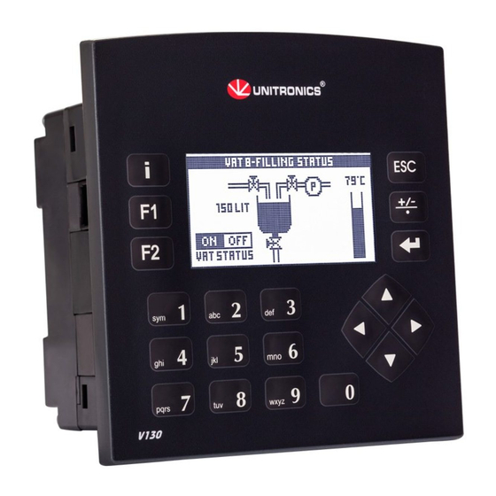
Vision™PLC+HMI
V130-33-TR6/V130-J-TR6
V350-35-TR6/V350-J-TR6
V430-J-RH6
General Description
All of the controllers covered in this guide are micro-PLC+HMIs, rugged programmable logic controllers
that comprise built-in operating panels and on-board I/Os.
Item
On-board I/O
Screen
Keypad
Function Keys
Com Port, Built-in
RS232/485
USB device,
mini-B
Com Ports, separate
order, user-installed
* V430J/V350/V350J comprises both RS232/485 and USB ports; note that only one channel may be used at a time.
Standard Kit Contents
Item
Controller
Terminal Blocks
Battery (installed)
Slides
(2 sets of key labels)
Mounting Brackets
Rubber Seal
Unitronics
Installation Guide
8 Digital Inputs,
including
2 Analog, 1 HSC/Shaft-
encoder inputs
6 Relay Outputs
V130-TR6
V130J-TR6
2.4"
Yes
None
Yes
None
The user may install a CANbus port (V100-17-CAN), and one of the following:
RS232/RS485 port (V100-17-RS4/V100-17-RS4X)
Ethernet (V100-17-ET2)
Profibus Slave (V100-17-PB1)
V130-TR6
V130J-TR6
None
Model Dependent
3.5" Color Touch
Yes
Yes*
None
Yes*
Yes
Yes
Yes
Yes (2 parts)
Yes
4 Analog Inputs (Current)
2 high-speed npn
Transistor Outputs (TR6 Only)
V350-TR6
V350J-TR6
None
Yes
Yes*
Yes*
V350-TR6
V350J-TR6
Yes
V430J-RH6
4.3" Color Touch
Yes*
Yes*
V430J-RH6
None
Yes (4 parts)
1
Advertisement

Related Manuals for Unitronics V130-33-TR6


Summary of Contents for Unitronics V130-33-TR6
- Page 1 Vision™PLC+HMI Installation Guide 8 Digital Inputs, 4 Analog Inputs (Current) V130-33-TR6/V130-J-TR6 including V350-35-TR6/V350-J-TR6 2 Analog, 1 HSC/Shaft- V430-J-RH6 encoder inputs 6 Relay Outputs 2 high-speed npn Transistor Outputs (TR6 Only) General Description All of the controllers covered in this guide are micro-PLC+HMIs, rugged programmable logic controllers that comprise built-in operating panels and on-board I/Os.
-
Page 2: Alert Symbols And General Restrictions
All examples and diagrams are intended to aid understanding, and do not guarantee operation. Unitronics accepts no responsibility for actual use of this product based on these examples. Please dispose of this product according to local and national standards and regulations. - Page 3 4. Tighten the bracket’s screws against the panel. Hold the bracket securely against the unit while tightening the screw. 5. When properly mounted, the controller is squarely situated in the panel cut-out as shown in the accompanying figures. V130/V350/V130J/V350J Unitronics...
- Page 4 DIN-rail Mounting (V130/V350/V130J/V350J) 1. Snap the controller onto the DIN rail as shown in the figure to the right. 2. When properly mounted, the controller is squarely situated on the DIN-rail as shown in the figure to the right. Unitronics...
- Page 5 - Input 1 can function as either counter reset, as part of a shaft-encoder, or as normal digital input. If input 0 high-speed counter (without reset), input 1 can function as normal digital input. Unitronics...
- Page 6 JP1 (all Inputs) npn (sink) pnp (source)* Inputs 6/7: Set as Digital or Analog Set to JP5 (Input 6) JP6 (Input 7) Digital* Analog Analog Inputs AN0/AN1: Set Type Set to JP3 (AN0) JP4 (AN1) Voltage* Current *Default settings Unitronics...
- Page 7 Vision™PLC+HMI I/O Wiring npn (sink) Input Input wiring HSC input wiring pnp (source) Input Input wiring HSC input wiring Shaft-encoder Unitronics...
- Page 8 To increase the life span of the relay output contacts and protect the device from potential damage by reverse EMF, connect: A clamping diode in parallel with each inductive DC load An RC snubber circuit in parallel with each inductive AC load Unitronics...
-
Page 9: Power Supply
These models comprise built-in ports: 1 USB and 1 RS232/RS485 (Port 1). Note that physically connecting a PC to the controller via USB suspends RS232/RS485 communications via Port 1. When the PC is disconnected, RS232/RS485 resumes. RS232/RS485 Port Turn off power before making communications connections. Unitronics... - Page 10 11. Setting RS232/RS485 Communication Parameters, V430J This port may be set to either RS232 or RS485 via DIP switches: The table shows the DIP switches factory default settings. Use the table to adapt the settings. Switch Settings Unitronics...
- Page 11 Do not force the board into place; doing so may damage the controller. 2. Replace the back cover of the controller and fasten the corner screws. Note that you must replace the back cover securely before powering up the controller. Unitronics...
- Page 12 Vision™PLC+HMI Installation Guide The information in this document reflects products at the date of printing. Unitronics reserves the right, subject to all applicable laws, at any time, at its sole discretion, and without notice, to discontinue or change the features, designs, materials and other specifications of its products, and to either permanently or temporarily withdraw any of the forgoing from the market.
Need help?
Do you have a question about the V130-33-TR6 and is the answer not in the manual?
Questions and answers