Advertisement
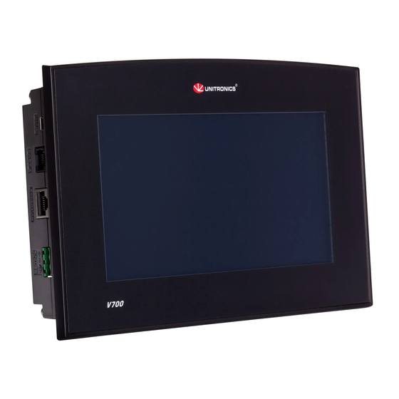
Vision™PLC+HMI
General Description
V700 PLC+HMI is programmable logic controller that comprise a built-in operating panel containing
a 7" Color Touchscreen
I/O Options
Screen
Keypad or
Function Keys
Programming Com
Port, Built-in
RS232/485
USB device,
mini-B
Ethernet
Com Ports,
separate order,
installed by user
* V700 comprises both RS232/485 and USB ports; note that only one channel may be used at a time.
Standard Kit Contents
Controller
Terminal Block
Battery
Mounting Brackets
Rubber Seal
Alert Symbols and General Restrictions
When any of the following symbols appear, read the associated information carefully.
Symbol
Meaning
Danger
Warning
Caution
Caution
Before using this product, the user must read and understand this document.
All examples and diagrams are intended to aid understanding, and do not guarantee operation.
Unitronics accepts no responsibility for actual use of this product based on these examples.
Please dispose of this product according to local and national standards and regulations.
Only qualified service personnel should open this device or carry out repairs.
Failure to comply with appropriate safety guidelines can cause severe injury or property damage.
Do not attempt to use this device with parameters that exceed permissible levels.
To avoid damaging the system, do not connect/disconnect the device when power is on.
Unitronics
Snap-in I/O Modules / I/O Expansion Modules
7" Color Touch
None
Yes*
Yes*
Yes
The user may install a CANbus port (V100-17-CAN), and one of the following:
RS232/RS485 port (V100-17-RS4/V100-17-RS4X)
Profibus Slave (V100-17-PB1)
Yes
Yes (3 pin)
Yes
Yes (4 parts)
Yes
Description
The identified danger causes physical and property damage.
The identified danger could cause physical and property damage.
Use caution.
Installation Guide
V700-T20BJ
V700-S-T20BJ
1
Advertisement
Table of Contents

Subscribe to Our Youtube Channel
Related Manuals for Unitronics Vision700


Summary of Contents for Unitronics Vision700
- Page 1 All examples and diagrams are intended to aid understanding, and do not guarantee operation. Unitronics accepts no responsibility for actual use of this product based on these examples. Please dispose of this product according to local and national standards and regulations.
-
Page 2: Environmental Considerations
Do not allow debris to fall inside the unit during installation. Ventilation: 10mm space required between controller’s top/bottom edges & enclosure walls. Install at maximum distance from high-voltage cables and power equipment. Mounting Dimensions Note that the Snap-in I/O module thickness is 23 mm (0.9”). Unitronics... - Page 3 3. Push the mounting brackets into their slots on the sides of the panel as shown in the figure below. 4. Tighten the bracket’s screws against the panel. Hold the bracket securely against the unit while tightening the screw. 5. When properly mounted, the controller is squarely situated in the panel cut-out as shown in the accompanying figures. Unitronics...
-
Page 4: Inserting The Battery
Allow for voltage drop and noise interference with I/O lines used over an extended distance. Use wire that is properly sized for the load. The controller and I/O signals must be connected to the same 0V signal. Unitronics... -
Page 5: Power Supply
Available types: RS232/RS485 isolated/non-isolated A CANbus port For the most updated information regarding ports and their installation, please refer to the Technical Library at www.unitronics.com. Turn off power before making communications connections. Always use the appropriate port adapters. Caution The USB port may be used for programming, OS download, and PC access. - Page 6 RJ45 Connector Pinout Ethernet LEDS Pin # Description Function T+ = Positive transmit signal Green ON when link (LNK) exists T- = Negative transmit signal R+ = Positive receive signal Yellow Blinks during (ACT) RX/TX R- = Negative receive signal Unitronics...
- Page 7 1. Locate the four buttons on the sides of the controller, two on either side. 2. Press the buttons and hold them down to open the locking mechanism. 3. Gently rock the module from side to side, easing the module from the controller. Unitronics...
- Page 8 Vision™ Installation Guide The information in this document reflects products at the date of printing. Unitronics reserves the right, subject to all applicable laws, at any time, at its sole discretion, and without notice, to discontinue or change the features, designs, materials and other specifications of its products, and to either permanently or temporarily withdraw any of the forgoing from the market.
Need help?
Do you have a question about the Vision700 and is the answer not in the manual?
Questions and answers