Advertisement
Quick Links
Advertisement

Related Manuals for FUFU & GAGA KF250004-01


Summary of Contents for FUFU & GAGA KF250004-01
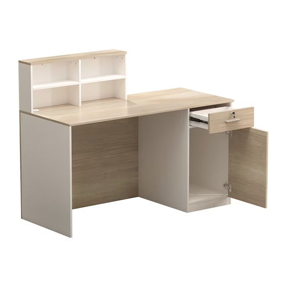
- Page 1 Reception Desk Version:08/12/2022 1/26...
- Page 2 IMPORTANT INFORMATION! please read the entire manual before starting to assemble and/or using this product.follow the manual thoroughly and keep it for further reference. AVOID SCRATCHES! In order to avoid scratching this furnuture should be assembled on a soft layer-could be a rug. IMPROVE EFFICIENCY ! Try to find a partner to install with you, which can speed up...
-
Page 3: Table Of Contents
Please prepare the following tools When installing, please carefully confirm whether each screw corresponds to the manual, accessories with similar shapes can be distinguished by size A x 54+1 B x 54+1 C x 20+1 D x 10 M5 x 42 mm 15 x 10 mm M3.5 x 12 mm M5 x 40 mm... - Page 4 4/26...
- Page 5 5/26...
-
Page 6: M5 X 42 Mm
A x 12 M5 x 42 mm Insert quickfit screw(A) into plate 1 and 2 with a screwdriver as shown. 6/26... - Page 7 A x 8 M5 x 42 mm Insert quickfit screw(A) into plate 3,4,5 with a screwdriver as shown. Please note both sides of plate 4 need to be inserted. 7/26...
- Page 8 B x 4 15 x 10 mm Connect plate 3 and 4 with plate 6 and turn cam locks(B) clockwise to tighten as shown. 180° B x 4 15 x 10 mm Connect plate 4 and 5 with plate 6 and turn cam locks(B) clockwise to tighten as shown.
- Page 9 B x 4 15 x 10 mm Attach the component to plate 2 and turn cam locks(B) clockwise to tighten as shown. 180° 9/26...
- Page 10 B x 8 H x 2 6 x 40 mm 15 x 10 mm Insert wooden dowel(H) into plate 2 at first. Cover plate 1 to plate 2,3,4,5 and turn cam locks(B) clockwise to tighten as shown. 180° 10/26...
- Page 11 A x 6 M5 x 42 mm Insert quickfit screw(A) into plate 7 with a screwdriver as shown. D x 6 M5 x 40mm Attach plate 7 to plate 3,4,5 with screw(D) as shown. 11/26...
- Page 12 A x 6 C x 2 M5 x 42mm M3.5 x 12mm Separate glide into two parts, fix slide rail 22 to plate 9 with screw(C) as shown. Insert quickfit screw(A) into plate 9 with a screwdriver as shown. Please pay attention to the holes where the accessories are inserted. 12/26...
- Page 13 A x 6 C x 2 M5 x 42mm M3.5 x 12mm Fix slide rail 22 to plate 10 with screw(C) as shown. Insert quickfit screw(A) into plate 10 with a screwdriver as shown. Please pay attention to the holes where the accessories are inserted. 13/26...
- Page 14 B x 6 H x 2 15 x 10 mm 6 x 40 mm Insert wooden dowel(H) into plate 11 at first. Attach plate 11,12 to plate 9 and turn cam locks(B) clockwise to tighten as shown. 180° 14/26...
- Page 15 B x 6 H x 2 15 x 10 mm 6 x 40 mm Insert wooden dowel(H) into plate 11 at first. Attach plate 10 to plate 11,12 and turn cam locks(B) clockwise to tighten as shown. 180° 15/26...
- Page 16 A x 6 M5 x 42 mm Insert quickfit screw(A) into plate 13 with a screwdriver as shown. A x 6 M5 x 42 mm Insert quickfit screw(A) into plate 14 with a screwdriver as shown. 16/26...
- Page 17 H x 4 6 x 40 mm Connect plate 13 and 14 with wooden dowel(H) as shown. H x 8 B x 8 15 x 10 mm 6 x 40 mm Attach plate 13,14 to plate 9,10 with wooden dowel(H) and turn cam locks(B) clockwise to tighten as shown.
- Page 18 H x 4 B x 4 15 x 10 mm 6 x 40 mm Attach plate 8 to plate 13,14 with wooden dowel(H) and turn cam locks(B) clockwise to tighten as shown. 180° 18/26...
-
Page 19: E X 4
E x 4 M6 x 12 mm Connect plate 8 and 9 with iron tube 21 using screw(E) as shown. 19/26... -
Page 20: F X 2
H x 6 B x 6 F x 2 15 x 10 mm M6 x 30 mm 6 x 40 mm Attach plate 7 to plate 8,9,10 with wooden dowel(H) and turn cam locks(B) clockwise to tighten as shown. Fix iron tube 21 to plate 7 with screw(F) as shown. -
Page 21: J X 2
C x 4 J x 2 L x 1 SET K x 1 M3.5 x 12 mm M4 x 18 mm Fix hinge(L) to plate 20 with screw(C), fix handle(K) to plate 20 with screw(J) as shown. 21/26... - Page 22 C x 8 M3.5 x 12 mm Attach plate 20 to 10 by fixing hinge with screw(C) as shown. 22/26...
-
Page 23: K X 1
G x 4 M x 1 M3 x 18 mm Fix part(M) to plate 15 with screw(G) as shown. J x 2 K x 1 A x 4 M5 x 42 mm M4 x 18 mm Insert quickfit screw(A) into plate 15 with a screwdriver as shown. - Page 24 B x 4 15 x 10 mm Attach plate 16,17 to plate 15 and turn cam locks(B) clockwise to tighten as shown. 180° Slide plate 19 into available slots as shown. 24/26...
-
Page 25: D X 4
D x 4 M5 x 40 mm Attach plate 18 to plate 16,17 with screw(D) as shown. C x 4 M3.5 x 12 mm Fix runner 22 to plate 16,17 with screw(C) as shown. 25/26... - Page 26 I x 1 Align the wire box(I) into the hole position. Align rails, slide the drawer. N x 8 Cover cam locks(B) using sticker(N) as shown. 26/26...
- Page 27 WARRANTY WARRANTY CLAIMS •There is a 30-day warranty for broken furniture or any other problems that do not work properly. The warranty will start from the date of purchase which must be verified by proof of purchase. •Before making a claim, we may be able to answer your query, simply call us. Please leave your purchase order number, along with some details of the problem, if you want a replacement part.
- Page 28 RETURNS CHANGED YOUR MIND AND NEED TO RETURN YOU ITEM? PLEASE FOLLOW THE BELOW INSTRUCTIONS: •If you have purchased and have simply changed your mind, follow the retailer’s instructions for returns. DEFECTIVE ITEMS •If your item is defective in any way, i.e. it doesn’t work but you can’t identify why, in the first instance, please call us.
Need help?
Do you have a question about the KF250004-01 and is the answer not in the manual?
Questions and answers