Table of Contents
Advertisement
Quick Links
Advertisement
Table of Contents

Subscribe to Our Youtube Channel
Related Manuals for Huawei UPSJZ-T Series


Summary of Contents for Huawei UPSJZ-T Series
- Page 1 UPSJZ-T-(1 kVA–3 kVA) User Manual Date 2022-08-15...
-
Page 2: About This Document
UPSJZ-T-(1 kVA–3 kVA) User Manual About This Document About This Document Purpose This document describes the UPSJZ-T-(1 kVA–3 kVA) series in terms of features, performance indicators, appearance, structure, working principles, installation, usage, operation, and maintenance. NO TE ● The UPS applies only to commercial and industrial use, rather than medical facilities and life support equipment. - Page 3 UPSJZ-T-(1 kVA–3 kVA) User Manual About This Document Symbol Description Indicates a potentially hazardous situation which, if not avoided, could result in equipment damage, data loss, performance deterioration, or unanticipated results. NOTICE is used to address practices not related to personal injury.
-
Page 4: Table Of Contents
UPSJZ-T-(1 kVA–3 kVA) User Manual Contents Contents About This Document........................ ii 1 Safety Information........................1 1.1 Personal Safety..................................2 1.2 Equipment Safety..................................3 1.2.1 UPS Safety....................................4 1.2.2 Battery Safety..................................5 1.3 Electrical Safety..................................10 1.4 Environmental Requirements............................14 1.5 Mechanical Safety.................................15 2 Overview.......................... - Page 5 UPSJZ-T-(1 kVA–3 kVA) User Manual Contents 5.3 Shutting Down the UPS..............................79 5.4 Transferring to Bypass Mode Manually.........................80 5.5 Transferring from Bypass Mode to Inverter Mode....................80 5.6 Switching to Battery Self-Check............................80 5.7 Enabling/Disabling the Buzzer Off..........................80 5.8 Manually Clearing an Alarm............................. 80 5.9 Checking the Alarm Cause..............................
-
Page 6: Safety Information
UPSJZ-T-(1 kVA–3 kVA) User Manual 1 Safety Information Safety Information Statement Before installing, operating, or maintaining the equipment, read this document, strictly follow the instructions provided herein, and follow all the safety instructions on the equipment and in this document. The DANGER, WARNING, CAUTION, and NOTICE statements in this document do not cover all the safety instructions. -
Page 7: Personal Safety
UPSJZ-T-(1 kVA–3 kVA) User Manual 1 Safety Information ● Damage caused during transportation by the customer or a third party authorized by the customer ● Storage conditions that do not meet the requirements specified in this document ● Failure to comply with local laws, regulations, and related standards due to the materials and tools prepared by the customer ●... -
Page 8: Equipment Safety
UPSJZ-T-(1 kVA–3 kVA) User Manual 1 Safety Information ● If there is a likelihood of personal injury or equipment damage during operations, immediately stop, report the case to the supervisor, and take feasible protective measures. ● Do not power on the equipment before it is installed or confirmed by professionals. -
Page 9: Ups Safety
UPSJZ-T-(1 kVA–3 kVA) User Manual 1 Safety Information 1.2.1 UPS Safety General Requirements NO TICE The category 2 (C2) UPS may cause radio interference when used in a residential environment. Additional measures may be needed to prevent the interference. ● The UPS is used for commercial and industrial purposes only. -
Page 10: Battery Safety
UPSJZ-T-(1 kVA–3 kVA) User Manual 1 Safety Information ● Exercise caution when manually shutting down the UPS inverter for transferring to bypass mode, or when adjusting the UPS output voltage level or output frequency. Doing so may affect the power supply to equipment. 1.2.2 Battery Safety D ANGER Do not connect the positive and negative poles of a battery or battery string... - Page 11 UPSJZ-T-(1 kVA–3 kVA) User Manual 1 Safety Information D ANGER Battery electrolyte is toxic and volatile. Do not get contact with leaked liquids or inhale gases in the case of battery leakage or abnormal odor. In such cases, stay away from the battery and contact professionals immediately. Professionals must wear safety goggles, rubber gloves, gas masks, and protective clothing, power off the equipment, remove the battery, and contact technical engineers.
- Page 12 UPSJZ-T-(1 kVA–3 kVA) User Manual 1 Safety Information WARNING Tighten the screws on copper bars or cables to the torque specified in this document. Periodically confirm whether the screws are tightened, check for rust, corrosion, or other foreign objects, and clean them up if any. Loose screw connections will result in excessive voltage drops or and batteries may catch fire when the current is high.
- Page 13 UPSJZ-T-(1 kVA–3 kVA) User Manual 1 Safety Information ● The customer sets battery operating parameters incorrectly. ● The customer uses different batteries together, causing acceleration of capacity attenuation. For example, the customer uses our batteries together with batteries of other vendors or with batteries of different rated capacity. ●...
- Page 14 UPSJZ-T-(1 kVA–3 kVA) User Manual 1 Safety Information ● Before unpacking batteries, check whether the packaging is intact. Do not use batteries with damaged packaging. If any damage is found, notify the carrier and manufacturer immediately. ● In an indoor scenario, you are advised to power on a battery within seven days after unpacking.
-
Page 15: Electrical Safety
UPSJZ-T-(1 kVA–3 kVA) User Manual 1 Safety Information ● Inhalation: Evacuate from contaminated areas, get fresh air immediately, and seek immediate medical attention. ● Eye contact: Immediately wash your eyes with water for at least 15 minutes, do not rub your eyes, and seek immediate medical attention. ●... - Page 16 UPSJZ-T-(1 kVA–3 kVA) User Manual 1 Safety Information D ANGER Prevent foreign matter from entering the equipment during operations. Otherwise, equipment damage, load power derating, power failure, or personal injury may occur. WARNING For the equipment that needs to be grounded, install the ground cable first when installing the equipment and remove the ground cable last when removing the equipment.
- Page 17 UPSJZ-T-(1 kVA–3 kVA) User Manual 1 Safety Information ● To avoid electric shock, do not connect safety extra-low voltage (SELV) circuits to telecommunication network voltage (TNV) circuits. ● If the equipment has multiple inputs, disconnect all the inputs before operating the equipment. ●...
- Page 18 UPSJZ-T-(1 kVA–3 kVA) User Manual 1 Safety Information ● Ensure that the slots and holes for routing cables are free from sharp edges, and that the positions where cables are routed through pipes or cable holes are equipped with cushion materials to prevent the cables from being damaged by sharp edges or burrs.
-
Page 19: Environmental Requirements
UPSJZ-T-(1 kVA–3 kVA) User Manual 1 Safety Information Figure 1-1 Wearing an ESD wrist strap ● When holding a board or a module with exposed circuit boards, hold its edge without touching any components. Do not touch the components with bare hands. -
Page 20: Mechanical Safety
UPSJZ-T-(1 kVA–3 kVA) User Manual 1 Safety Information ● If any liquid is detected inside the equipment, disconnect the power supply immediately and contact the administrator. ● To prevent fire due to high temperature, ensure that the ventilation vents or heat dissipation system are not blocked when the equipment is running. - Page 21 UPSJZ-T-(1 kVA–3 kVA) User Manual 1 Safety Information ● Do not install other devices on the top of the equipment without evaluation by the Company. ● When performing operations (such as hoisting or installing an awning) over the top of the equipment, take measures to protect the equipment against damage.
-
Page 22: Overview
UPSJZ-T-(1 kVA–3 kVA) User Manual 2 Overview Overview 2.1 Model Number Description This document describes the following UPS models. Table 2-1 UPS models Model Represented By Remarks UPSJZ-T1KS 1K-standard backup time 1. The tower-mounted model-tower mounted- model provides three configurations: 1 kVA, 2 kVA, and 3 kVA. -
Page 23: Working Principle
UPSJZ-T-(1 kVA–3 kVA) User Manual 2 Overview Table 2-2 UPS model number details Item Description Product UPS: uninterruptible power system category Product series UPS type ● T: tower-mounted UPS ● R: rack-mounted UPS Output ● 1K: 1 kVA capacity ● 2K: 2 kVA (VA) ●... -
Page 24: Product Structure
UPSJZ-T-(1 kVA–3 kVA) User Manual 2 Overview 2.3 Product Structure Figure 2-3 Rear views of UPSs with standard and long backup time (1) Mains input socket (1 kVA/2 kVA: C14; 3 (2) Input circuit breaker kVA: C20) (4) RS232 port (3) USB port (5) Optional card slot (6) External battery connector... - Page 25 UPSJZ-T-(1 kVA–3 kVA) User Manual 2 Overview NO TE a: The USB port supports the standard Modbus protocol and can be connected to the network management system (NMS) through a USB cable. The port is also protected by a security mechanism. 2022-08-15...
-
Page 26: Installation
UPSJZ-T-(1 kVA–3 kVA) User Manual 3 Installation Installation 3.1 Installation Preparations Floor Loading Capacity The floor can bear the weight of the UPS and its optional components. In the case of rack-mounted installation, ensure that the floor can also bear the weight of the rack. -
Page 27: Tools
UPSJZ-T-(1 kVA–3 kVA) User Manual 3 Installation Figure 3-1 Clearances 3.2 Tools The onsite operation personnel can select tools based on the site requirements. Personal protective equipment Safety helmet Goggles Protective shoes Reflective vest ESD gloves Insulated gloves Protective gloves 2022-08-15... - Page 28 UPSJZ-T-(1 kVA–3 kVA) User Manual 3 Installation Hardware installation tools Flat-head Phillips insulated Utility knife Marker insulated torque torque screwdriver screwdriver (2 mm) (M4/M6) Cable installation tools Wire stripper RJ45 crimping Electro-hydraulic Heat gun tool pliers Cord end terminal Diagonal pliers Crimping tool Hydraulic pliers crimping tool...
-
Page 29: Installing A Ups
UPSJZ-T-(1 kVA–3 kVA) User Manual 3 Installation Measurement instruments Clamp meter Multimeter Network tester Engineering auxiliary materials Label Cable tie Cotton cloth Heat-shrink tubing Insulation tape Other tools Electrician's knife Tweezers Brush Vacuum cleaner 3.3 Installing a UPS Procedure Step 1 Check that the UPS package is intact without obvious dents or damage. 2022-08-15... -
Page 30: Connecting Cables To A Ups
UPSJZ-T-(1 kVA–3 kVA) User Manual 3 Installation Step 2 Unpack the UPS and check that all fittings comply with the packing list. Step 3 Take out the UPS and place it on a stable surface, as shown in Figure 3-2. Figure 3-2 Installing a UPS ----End 3.4 Connecting Cables to a UPS... - Page 31 UPSJZ-T-(1 kVA–3 kVA) User Manual 3 Installation Figure 3-4 Connecting output cables for UPS loads (long backup time model) Step 2 Connect battery cables. (This step is for the UPS with long backup time. The UPS with standard backup time has built-in batteries and does not have external battery ports.) UPSJZ-T-(1 kVA–3 kVA) For details about how to install a battery box, see the...
- Page 32 UPSJZ-T-(1 kVA–3 kVA) User Manual 3 Installation RMS- Install an optional communications card for the UPS. For details, see the SNMP01B SNMP Card User Manual , RMS-RELAY01B User Manual , and RMS- MODBUS01B User Manual . Figure 3-6 Installing optional cards for UPSs (standard backup time models) Figure 3-7 Installing optional cards for UPSs (long backup time models) NO TE The UPS provides an optional intelligent slot for installing an SNMP card, a dry contact...
- Page 33 UPSJZ-T-(1 kVA–3 kVA) User Manual 3 Installation Figure 3-8 Connecting communications cables for UPSs (standard backup time models) Figure 3-9 Connecting communications cables for UPSs (long backup time models) NO TE ● The USB channel supports a serial data communications protocol between the UPS and a PC.
-
Page 34: Verifying The Installation
UPSJZ-T-(1 kVA–3 kVA) User Manual 3 Installation Figure 3-10 Connecting input cables for UPSs (standard backup time models) Figure 3-11 Connecting input cables for UPSs (long backup time models) ----End 3.5 Verifying the Installation Table 3-1 lists the check items. Table 3-1 Post-installation checklist Item Expected Result... - Page 35 UPSJZ-T-(1 kVA–3 kVA) User Manual 3 Installation Item Expected Result Cable labels Both ends of each cable are labeled. Labels are easy to understand. Ground cable connection The UPS ground cable is securely connected to the equipment room ground bar. Use a multimeter to measure the resistance between the UPS ground cable and the equipment room ground bar.
-
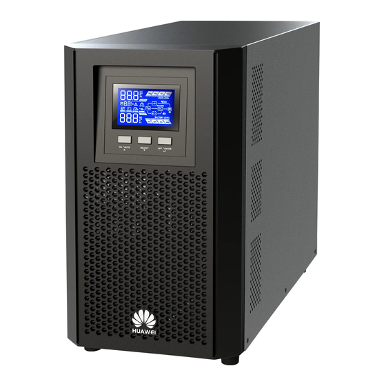
Page 36: Control Panel
UPSJZ-T-(1 kVA–3 kVA) User Manual 4 Control Panel Control Panel 4.1 LCD The UPS control panel is located on the front panel of the chassis. The control panel allows you to control and operate the UPS, view the running status, set parameters, and view alarms. - Page 37 UPSJZ-T-(1 kVA–3 kVA) User Manual 4 Control Panel Display Function Indicates the backup time, alarm ID, and CF (only displayed in converter mode) cyclically in digits. H: hour; M: minute; S: second Converter mode information Indicates that the UPS is in converter mode. Alarm information Indicates that alarms are generated.
-
Page 38: Buzzer Alarm Tones
UPSJZ-T-(1 kVA–3 kVA) User Manual 4 Control Panel Display Function Indicates that the UPS is in ECO mode. Indicates that the converter circuit is working. Indicates that the output socket is delivering power. Battery information Indicates the current battery state of charge (SOC) by level: ●... -
Page 39: Lcd Character Display
UPSJZ-T-(1 kVA–3 kVA) User Manual 4 Control Panel 4.3 LCD Character Display Table 4-3 LCD character display Acronyms and Display Meaning Abbreviations Enabled Disabled Exit Frequency conversion Temperature Charging Unstable bypass frequency EEPROM error Voltage Frequency Bypass overvoltage Bypass undervoltage Capacity Discharging duration Energy saving mode... -
Page 40: Buttons
UPSJZ-T-(1 kVA–3 kVA) User Manual 4 Control Panel Acronyms and Display Meaning Abbreviations Dynamic Host Configuration Protocol (DHCP) function IP ADS IP address SUB NET Subnet mask GAT UAY Gateway No battery alarm disabled 4.4 Buttons You can start or shut down the system, and view and set parameters through the three buttons on the LCD. - Page 41 UPSJZ-T-(1 kVA–3 kVA) User Manual 4 Control Panel Table 4-4 Button description Button Function ON/MUTE ● Starting the inverter: Hold down the ON/MUTE button for more than 5s to start the UPS inverter. ● Cold-starting the UPS using batteries: Hold down the ON/MUTE button for less than 15s to start the UPS inverter.
- Page 42 UPSJZ-T-(1 kVA–3 kVA) User Manual 4 Control Panel Button Function SELECT ● Setting mode: – When the UPS is in standby mode or bypass mode, hold down the SELECT button for 2– 4s to enter UPS setting mode. In this case, all parameters can be set.
-
Page 43: Parameter Settings
UPSJZ-T-(1 kVA–3 kVA) User Manual 4 Control Panel Button Function ON/MUTE+SELECT ● Transferring to bypass mode: When the input power is normal and the UPS works in normal mode, hold down the ON/MUTE and SELECT buttons at the same time for 5s, the UPS transfers to bypass mode. - Page 44 UPSJZ-T-(1 kVA–3 kVA) User Manual 4 Control Panel Figure 4-3 Parameter settings on the LCD When the UPS is in standby mode or bypass mode, hold down the SELECT button for 5s to enter UPS setting mode. In this case, all parameters can be set. When the UPS is in normal mode or battery mode, hold down the SELECT button for 2–4s to enable or disable the buzzer off function (BUZ), set the DHCP function (DHP), and view the IP address (IP), subnet mask (SUB), and gateway (GAT).
- Page 45 UPSJZ-T-(1 kVA–3 kVA) User Manual 4 Control Panel Display Description Enable or disable the converter mode: 50: The output frequency is fixed at 50 Hz, and the converter mode is enabled. 60: The output frequency is fixed at 60 Hz, and the converter mode is enabled.
- Page 46 UPSJZ-T-(1 kVA–3 kVA) User Manual 4 Control Panel ● Minimum input voltage in bypass mode setting Display Description You can adjust the minimum input voltage in bypass mode using ▲ and ▼. 170–220: The voltage can be set from 170 V AC (default) to 220 V AC. NO TE The minimum input voltage in bypass mode must be lower than the minimum voltage allowed in ECO mode.
- Page 47 UPSJZ-T-(1 kVA–3 kVA) User Manual 4 Control Panel Display Description Enable or disable the ECO function: ENA: The ECO mode is enabled. DIS: The ECO mode is disabled (default). ● Maximum allowable voltage in ECO mode setting Display Description You can adjust the maximum input voltage in ECO mode using ▲...
- Page 48 UPSJZ-T-(1 kVA–3 kVA) User Manual 4 Control Panel Display Description Enable or disable the buzzer off function: ENA: The buzzer is muted. DIS: The buzzer is unmuted (default). ● Automatic startup Display Description Automatic startup upon power-on: ENA: The function of automatic startup upon power-on is enabled.
- Page 49 UPSJZ-T-(1 kVA–3 kVA) User Manual 4 Control Panel Display Description UPS IP address: The displayed parameter cannot be set. Press ▲ or ▼ to switch between different screens. On the ESC screen, press the OFF/ ENTER button to exit. (The default value is 192.168.0.10.) ●...
-
Page 50: Working Mode
UPSJZ-T-(1 kVA–3 kVA) User Manual 4 Control Panel Display Description Set the no battery alarm function: ENA: The no battery alarm is not reported. DIS: The no battery alarm is reported (default). ● Exiting setting Display Description Exit from the parameter settings screen. - Page 51 UPSJZ-T-(1 kVA–3 kVA) User Manual 4 Control Panel Working Mode Description Display Converter mode When the input frequency is within the allowed range, the UPS sets the output frequency to 50 Hz or 60 Hz and charges batteries. Battery mode When the input voltage is abnormal or an outage occurs, the UPS...
-
Page 52: Alarm Handling
UPSJZ-T-(1 kVA–3 kVA) User Manual 4 Control Panel 4.7 Alarm Handling NO TE When an alarm can be manually cleared, hold down the OFF/ENTER button for more than 2 seconds to manually clear the alarm. Table 4-6 Alarm handling Alarm ID Cause ID Name Severity... - Page 53 UPSJZ-T-(1 kVA–3 kVA) User Manual 4 Control Panel Alarm ID Cause ID Name Severity Clearance Trigger Impact Solution Mode Condition on the System Bypass Minor The alarm The UPS Possible frequency bypass remains cause: abnormal automatic frequency in the ally is beyond original bypass...
- Page 54 UPSJZ-T-(1 kVA–3 kVA) User Manual 4 Control Panel Alarm ID Cause ID Name Severity Clearance Trigger Impact Solution Mode Condition on the System Start Critical This If this ● Possibl timeout alarm inverter alarm is needs to output generated cause: voltage is when the manually...
- Page 55 UPSJZ-T-(1 kVA–3 kVA) User Manual 4 Control Panel Alarm ID Cause ID Name Severity Clearance Trigger Impact Solution Mode Condition on the System suppor Minor The alarm Discharge The UPS Possible ends in cannot cause: automatic battery start. ally mode or battery cleared.
- Page 56 UPSJZ-T-(1 kVA–3 kVA) User Manual 4 Control Panel Alarm ID Cause ID Name Severity Clearance Trigger Impact Solution Mode Condition on the System Battery Minor The alarm Batteries This ● Possibl disconnec are not alarm automatic connected does not cause: ally affect the cleared.
- Page 57 UPSJZ-T-(1 kVA–3 kVA) User Manual 4 Control Panel Alarm ID Cause ID Name Severity Clearance Trigger Impact Solution Mode Condition on the System Battery Critical This ● Possibl overvolta alarm voltage of number needs to each cause: battery batteries manually exceeds exceeds actual...
- Page 58 UPSJZ-T-(1 kVA–3 kVA) User Manual 4 Control Panel Alarm ID Cause ID Name Severity Clearance Trigger Impact Solution Mode Condition on the System when Minor This The UPS alarm is voltage of automatic batteri automatic each ally es are ally battery transfers discon...
- Page 59 UPSJZ-T-(1 kVA–3 kVA) User Manual 4 Control Panel Alarm ID Cause ID Name Severity Clearance Trigger Impact Solution Mode Condition on the System Battery Critical This ● Possibl undervolt alarm voltage of number needs to each cause: battery is batteries manually lower is less...
- Page 60 UPSJZ-T-(1 kVA–3 kVA) User Manual 4 Control Panel Alarm ID Cause ID Name Severity Clearance Trigger Impact Solution Mode Condition on the System Minor The alarm A UPS mains standard supply automatic model, voltage in non- ally alarm will battery cleared.
- Page 61 UPSJZ-T-(1 kVA–3 kVA) User Manual 4 Control Panel Alarm ID Cause ID Name Severity Clearance Trigger Impact Solution Mode Condition on the System Minor The alarm ation voltage of power require automatic each supply to ments. ally battery is ● Possibl cleared.
- Page 62 UPSJZ-T-(1 kVA–3 kVA) User Manual 4 Control Panel Alarm ID Cause ID Name Severity Clearance Trigger Impact Solution Mode Condition on the System Internal Critical This The bus The UPS Possible fault alarm voltage is cannot cause: needs to lower start if The soft- than 320...
- Page 63 UPSJZ-T-(1 kVA–3 kVA) User Manual 4 Control Panel Alarm ID Cause ID Name Severity Clearance Trigger Impact Solution Mode Condition on the System Internal Critical This The bus If this ● Possibl fault alarm voltage alarm is needs to exceeds generated cause: 450 V.
- Page 64 UPSJZ-T-(1 kVA–3 kVA) User Manual 4 Control Panel Alarm ID Cause ID Name Severity Clearance Trigger Impact Solution Mode Condition on the System ● Possibl cause: hardw are is damag Measu Contac t your dealer technic suppor 2022-08-15...
- Page 65 UPSJZ-T-(1 kVA–3 kVA) User Manual 4 Control Panel Alarm ID Cause ID Name Severity Clearance Trigger Impact Solution Mode Condition on the System Internal Critical This The bus If this ● Possibl fault alarm voltage is alarm is needs to lower generated cause:...
- Page 66 UPSJZ-T-(1 kVA–3 kVA) User Manual 4 Control Panel Alarm ID Cause ID Name Severity Clearance Trigger Impact Solution Mode Condition on the System Internal Minor The alarm An error Possible fault occurs in paramete cause: automatic rs of the ally EEPROM.
- Page 67 UPSJZ-T-(1 kVA–3 kVA) User Manual 4 Control Panel Alarm ID Cause ID Name Severity Clearance Trigger Impact Solution Mode Condition on the System Internal Critical The first If this ● Possibl fault three inverter alarm is alarms output generated cause: voltage is when the cleared...
- Page 68 UPSJZ-T-(1 kVA–3 kVA) User Manual 4 Control Panel Alarm ID Cause ID Name Severity Clearance Trigger Impact Solution Mode Condition on the System technic suppor ● Possibl cause: output short- circuite Measu Check wheth er the output short- circuite 2022-08-15...
- Page 69 UPSJZ-T-(1 kVA–3 kVA) User Manual 4 Control Panel Alarm ID Cause ID Name Severity Clearance Trigger Impact Solution Mode Condition on the System Internal Critical This If this ● Possibl fault alarm difference alarm is needs to between generated cause: when the manually absolute...
- Page 70 UPSJZ-T-(1 kVA–3 kVA) User Manual 4 Control Panel Alarm ID Cause ID Name Severity Clearance Trigger Impact Solution Mode Condition on the System Internal Critical This The UPS ● Possibl fault alarm ambient transfers needs to temperat to bypass cause: mode.
- Page 71 UPSJZ-T-(1 kVA–3 kVA) User Manual 4 Control Panel Alarm ID Cause ID Name Severity Clearance Trigger Impact Solution Mode Condition on the System Clean foreign objects around fan. If alarm persists contact your dealer technic suppor Internal Minor The alarm This Possible fault...
- Page 72 UPSJZ-T-(1 kVA–3 kVA) User Manual 4 Control Panel Alarm ID Cause ID Name Severity Clearance Trigger Impact Solution Mode Condition on the System Internal Critical This The UPS Possible fault alarm voltage of transfers cause: needs to each to bypass battery mode.
- Page 73 UPSJZ-T-(1 kVA–3 kVA) User Manual 4 Control Panel Alarm ID Cause ID Name Severity Clearance Trigger Impact Solution Mode Condition on the System Output Minor The alarm This Possible overload bypass alarm cause: automatic output does not The load ally load is affect the exceeds...
- Page 74 UPSJZ-T-(1 kVA–3 kVA) User Manual 4 Control Panel Alarm ID Cause ID Name Severity Clearance Trigger Impact Solution Mode Condition on the System Inverter Critical This ● In ● In Possible output alarm battery battery cause: overload needs to mode, mode, The load timeout...
- Page 75 UPSJZ-T-(1 kVA–3 kVA) User Manual 4 Control Panel Alarm ID Cause ID Name Severity Clearance Trigger Impact Solution Mode Condition on the System reporte ● In normal mode (the bypass abnor mal), transfe rs to output when overlo aded reports overlo fault.
- Page 76 UPSJZ-T-(1 kVA–3 kVA) User Manual 4 Control Panel Alarm ID Cause ID Name Severity Clearance Trigger Impact Solution Mode Condition on the System Minor The alarm The UPS The UPS ● Possibl bypass transfers transfers automatic to bypass to bypass cause: ally mode.
- Page 77 UPSJZ-T-(1 kVA–3 kVA) User Manual 4 Control Panel Alarm ID Cause ID Name Severity Clearance Trigger Impact Solution Mode Condition on the System capacit Measu Lower load or replace with a larger- capacit y UPS. 2022-08-15...
- Page 78 UPSJZ-T-(1 kVA–3 kVA) User Manual 4 Control Panel Alarm ID Cause ID Name Severity Clearance Trigger Impact Solution Mode Condition on the System Minor The alarm The UPS The UPS ● Possibl battery transfers transfers automatic to battery to battery cause: ally mode.
- Page 79 UPSJZ-T-(1 kVA–3 kVA) User Manual 4 Control Panel Alarm ID Cause ID Name Severity Clearance Trigger Impact Solution Mode Condition on the System Minor The alarm ● The If the ● Check bypass inverte bypass is wheth automatic r is not abnormal, ally started...
-
Page 80: Alarm Indicators
UPSJZ-T-(1 kVA–3 kVA) User Manual 4 Control Panel 4.8 Alarm Indicators Table 4-7 Alarm indicator description Alarm Description Display (Blinking) Buzzer Tone Low battery Beeps once every second. Overload Beeps twice every second. Batteries not connected Beeps once every second. Overcharge Beeps once every second. -
Page 81: Operations
UPSJZ-T-(1 kVA–3 kVA) User Manual 5 Operations Operations 5.1 Checking Before Power-On ● AC cable colors comply with local regulations. ● The input and output are not short-circuited. ● Cables and terminals are securely connected. ● Battery cables and terminals are correctly connected. Otherwise, the UPS may be damaged. -
Page 82: Starting A Ups
UPSJZ-T-(1 kVA–3 kVA) User Manual 5 Operations 5.2 Starting a UPS NO TICE ● If no buttons are pressed for more than 30s in UPS setting mode, the LCD home screen is displayed. ● If no battery packs are connected to the UPS with long backup time, the buzzer keeps buzzing. - Page 83 UPSJZ-T-(1 kVA–3 kVA) User Manual 5 Operations NO TE In UPS setting mode, hold down the ON/MUTE button for more than 3s to go to the previous option after a beep sound; hold down the SELECT button for more than 3s to go to the next option after a beep sound;...
-
Page 84: Shutting Down The Ups
UPSJZ-T-(1 kVA–3 kVA) User Manual 5 Operations with long backup time is 18 Ah. The capacity can be set in the range of 18– 999 Ah. Figure 5-4 Setting the battery capacity Start the inverter. After power-on, the UPS generates no output by default. Hold down the ON/ MUTE button on the front panel for more than 5s to start the UPS inverter. -
Page 85: Transferring To Bypass Mode Manually
UPSJZ-T-(1 kVA–3 kVA) User Manual 5 Operations 5.4 Transferring to Bypass Mode Manually When the input power is normal and the UPS works in normal mode, hold down the ON/MUTE and SELECT buttons at the same time for 5s, and then the UPS transfers to bypass mode. -
Page 86: Checking The Alarm Cause
UPSJZ-T-(1 kVA–3 kVA) User Manual 5 Operations 5.9 Checking the Alarm Cause Hold down the SELECT and OFF/ENTER buttons at the same time for 5s, and the alarm cause ID screen is displayed. View the previous alarm and the next alarm by pressing the ON/MUTE button and the SELECT button respectively. -
Page 87: Storage And Maintenance
UPSJZ-T-(1 kVA–3 kVA) User Manual 6 Storage and Maintenance Storage and Maintenance 6.1 Storage The correct way of storing the UPS is standing the UPS without unpacking in a dry place. For a standard UPS model, charge it for 5 hours before storage. During storage, charge and maintain it according to the following table. -
Page 88: Routine Maintenance
UPSJZ-T-(1 kVA–3 kVA) User Manual 7 Routine Maintenance Routine Maintenance 7.1 UPS Maintenance ● Only trained personnel are allowed to perform maintenance tasks. Before performing operations on the equipment, wear ESD clothes, ESD gloves, and an ESD wrist strap. Remove conductive objects such as jewelry and watches to avoid electric shocks or burns. - Page 89 UPSJZ-T-(1 kVA–3 kVA) User Manual 7 Routine Maintenance Item Expected Result Troubleshooting Maintenance Interval Monitoring panel According to the If an alarm is Monthly status icons on present, rectify the LCD, all units the fault by are operating checking the properly.
-
Page 90: Battery Maintenance
UPSJZ-T-(1 kVA–3 kVA) User Manual 7 Routine Maintenance 7.2 Battery Maintenance NO TICE This section describes the general maintenance requirements for external batteries. Before operating batteries, read through the battery user manual provided by the manufacturer, especially the safety precautions and correct connection methods. - Page 91 UPSJZ-T-(1 kVA–3 kVA) User Manual 7 Routine Maintenance Battery Routine Maintenance Table 7-2 Battery routine maintenance Item Expected Result Troubleshooting Maintenance Interval Battery No battery Identify the alarm Monthly management management cause based on alarm alarm is the alarm generated. information.
- Page 92 UPSJZ-T-(1 kVA–3 kVA) User Manual 7 Routine Maintenance Item Expected Result Troubleshooting Maintenance Interval Battery string ● Equalized 1. If the voltage Monthly charging voltage charging drop between voltage: 14.16 the battery V x Number of string output batteries terminals and (tolerance: the battery ±1%)
- Page 93 UPSJZ-T-(1 kVA–3 kVA) User Manual 7 Routine Maintenance Item Expected Result Troubleshooting Maintenance Interval Battery The settings of Set parameters Quarterly management battery correctly. parameter management settings parameters meet the requirements in the user manual. Tightness of The torque marks Take photos from Quarterly battery screws...
- Page 94 UPSJZ-T-(1 kVA–3 kVA) User Manual 7 Routine Maintenance Item Expected Result Troubleshooting Maintenance Interval Battery 1. When battery 1. Rectify any Annually connection strings are abnormal powered off, connection. check the 2. If the fault reliability of persists, each contact connection technical point from...
-
Page 95: Troubleshooting
UPSJZ-T-(1 kVA–3 kVA) User Manual 8 Troubleshooting Troubleshooting If a UPS runs abnormally, rectify the fault by referring to the following table. Table 8-1 Faults and troubleshooting measures Symptom Possible Cause Measure The active power supply The mains input power Check that the input is normal, but the LCD is cable may be loose. - Page 96 UPSJZ-T-(1 kVA–3 kVA) User Manual 8 Troubleshooting Symptom Possible Cause Measure Batteries provide backup Batteries are not fully Charge batteries for at power for a shorter charged. least 5 hours and then period than the specified check the battery SOC. If time.
-
Page 97: Technical Specifications
UPSJZ-T-(1 kVA–3 kVA) User Manual 9 Technical Specifications Technical Specifications 9.1 Physical Specifications Table 9-1 Physical specifications Model Net Dimensions (H x W Net Weight x D) UPSJZ-T1KS 220 mm x 145 mm x 282 9.4 kg UPSJZ-T1KL 220 mm x 145 mm x 282 4.6 kg UPSJZ-T2KS 220 mm x 145 mm x 397... -
Page 98: Mains Input Electrical Specifications
UPSJZ-T-(1 kVA–3 kVA) User Manual 9 Technical Specifications Environmental 1 kVA 2 kVA 3 kVA Specifications Relative humidity 0%–95% RH (non-condensing) Altitude ● 0–2000 m: The power is not derated. ● 2000–4000 m: The power is derated by 1% for each additional 100 m. -
Page 99: Bypass Input Electrical Specifications
UPSJZ-T-(1 kVA–3 kVA) User Manual 9 Technical Specifications Specifications 1 kVA 2 kVA 3 kVA Maximum ● 290 V AC±5% (load rate: less than 80%) recovery ● 270 V AC±5% (load rate: greater than 80%) voltage Input power factor (100% >... - Page 100 UPSJZ-T-(1 kVA–3 kVA) User Manual 9 Technical Specifications Specifications 1 kVA 2 kVA 3 kVA Output voltage precision ±1% Output frequency ● In normal mode, the frequency is 50/60 Hz with a tolerance of ±3 Hz. The output frequency tracks the input frequency. ●...
-
Page 101: Battery Electrical Specifications
UPSJZ-T-(1 kVA–3 kVA) User Manual 9 Technical Specifications Specifications 1 kVA 2 kVA 3 kVA Dynamic voltage transient ±5% Average frequency tracking 1 Hz/s rate Transfer time Transfer from normal mode to battery mode Transfer from 4 ms (100% resistive loads) bypass mode to ECO mode or conversely... - Page 102 UPSJZ-T-(1 kVA–3 kVA) User Manual 9 Technical Specifications Specifications 1 kVA 2 kVA 3 kVA Battery type Valve-regulated lead-acid (VRLA) battery, 12 V Battery capacity 9 Ah Backup time Standard > 4 minutes (at full rated load) backup time model Long backup Depends on the capacity of the external time model...
-
Page 103: Eco Specifications
UPSJZ-T-(1 kVA–3 kVA) User Manual 9 Technical Specifications Battery Load 1 kVA UPS 2 kVA UPS 3 kVA UPS Backup Time Backup Time Backup Time (Minute) (Minute) (Minute) NO TE ● The backup time is the test data before delivery. ●... -
Page 104: Safety Regulations And Emc
UPSJZ-T-(1 kVA–3 kVA) User Manual 9 Technical Specifications 9.9 Safety Regulations and EMC Table 9-10 Safety regulations and EMC Item Standards Compliance Conducted emission IEC 62040-2, C2 (CE) Radiated emission (RE) IEC 62040-2, C2 Low-frequency signal IEC 61000-2-2 immunity ESD immunity IEC 61000-4-2 Conducted IEC 61000-4-6... -
Page 105: A Acronyms And Abbreviations
UPSJZ-T-(1 kVA–3 kVA) User Manual A Acronyms and Abbreviations Acronyms and Abbreviations Conformité Européenne economy control operation EEPROM electrically erasable programmable read-only memory HTTP Hypertext Transfer Protocol liquid crystal display power factor correction RS232 Recommend Standard 232 SNMP Simple Network Management Protocol THDv total harmonic distortion of output voltage...
Need help?
Do you have a question about the UPSJZ-T Series and is the answer not in the manual?
Questions and answers