Nortel 1110 Installation And Operation Manual
Nortel networks communication server 1000 release 4.5
Hide thumbs
Also See for 1110:
- Fundamentals (572 pages) ,
- User manual (120 pages) ,
- Reference manual (6 pages)
Table of Contents
Advertisement
Quick Links
Download this manual
See also:
User Manual
Title page
Nortel Communication Server 1000
Nortel Networks Communication Server 1000 Release 4.5
IP Phones
Description, Installation, and Operation
Document Number: 553-3001-368
Document Release: Standard 26.00
Date: August 2007
Year Publish FCC TM
Copyright © 2007 Nortel Networks. All Rights Reserved.
Produced in Canada
The information in this document is subject to change without notice. The statements, configurations, technical
data, and recommendations in this document are believed to be accurate and reliable, but are presented
without express or implied warranty. Users must take full responsibility for their applications of any products
specified in this document. The information in this document is proprietary to Nortel Networks.
Nortel, the Nortel Logo, the Globemark, SL-1, Meridian 1, and Succession are trademarks of Nortel Networks.
Advertisement
Chapters
Table of Contents

Related Manuals for Nortel 1110


Summary of Contents for Nortel 1110
- Page 1 Users must take full responsibility for their applications of any products specified in this document. The information in this document is proprietary to Nortel Networks. Nortel, the Nortel Logo, the Globemark, SL-1, Meridian 1, and Succession are trademarks of Nortel Networks.
-
Page 3: Revision History
CR Q01478322. See page 123, and page 357. March 2007 Standard 22.00. This document is up-issued to support Communication Server 1000 Release 4.5. This document is up-issued to support the addition of IP Phone 1110. IP Phones Description, Installation, and Operation Page 3 of 630... - Page 4 Page 4 of 630 January 2007 Standard 21.00. Not issued. December 2006 Standard 20.00. This document is up-issued to include the addition of the Expansion Module for IP Phone Series. October 2006 Standard 19.00. This document is up-issued to include updated content due to CR Q01462514.
- Page 5 Standard 3.00. This document is up-issued to support Communication Server 1000 Release 4.0. June 2004 Standard 2.00. This document is up-issued to include the Nortel Networks Mobile Voice Client 2050. October 2003 Standard 1.00. This document is a new document for Succession 3.0 Software.
- Page 6 Page 6 of 630 553-3001-368 Standard 26.00 August 2007...
-
Page 7: Table Of Contents
How to get Help ......Getting help from the Nortel web site ...... - Page 8 Removing an IP Phone 2004 from service ..... . Nortel IP Phone 2002 ..... . . 111 Contents .
- Page 9 Removing an IP Phone 2002 from service ..... . Nortel IP Phone 2007 ..... . . 149 Contents ..
- Page 10 Operating parameters ........Nortel IP Softphone 2050 ....203 Contents .
- Page 11 Removing an IP Softphone 2050 from service ....Nortel Mobile Voice Client 2050 ....233 Contents ..
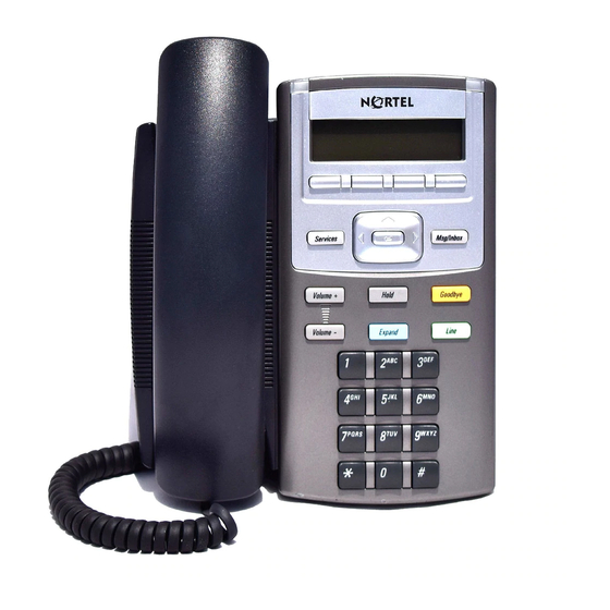
- Page 12 Redeploying an IP Phone 1110 ....... Replacing an IP Phone 1110 ....... .
- Page 13 Removing an IP Phone 1110 from service ..... . Nortel IP Phone 1120E ..... . 343 Contents ..
-
Page 14: Nortel Ip Phone 1150E
Removing an IP Phone 1140E from service ..... Nortel IP Phone 1150E ..... . 427 Contents . - Page 15 Bluetooth wireless technology ....... Reinstalling an IP Phone 1150E ......Replacing an IP Phone 1150E ..
- Page 16 Page 16 of 630 SRTP media encryption ........Appendix A: Specifications .
- Page 17 Introduction ..........Text-based diagnostic utilities ..
- Page 18 Contents Page 18 of 630 553-3001-368 Standard 26.00 August 2007...
-
Page 19: List Of Procedures
Page 19 of 630 List of procedures Procedure 1 Configuring the IP Phone 2001 ....52 Procedure 2 Installing the IP Phone 2001 for the first time using manual configuration . - Page 20 Page 20 of 630 Procedure 10 Installing the IP Phone 2004 for the first time using manual configuration ....92 Procedure 11 Installing an IP Phone 2004 for the first time using DHCP .
- Page 21 List of procedures Page 21 of 630 Procedure 22 Changing the TN of an existing IP Phone 2002 ..146 Procedure 23 Replacing an IP Phone 2002 ..... . 147 Procedure 24 Removing an IP Phone 2002 from service .
- Page 22 Page 22 of 630 Procedure 35 Installing the IP Softphone 2050 on the PC (new installation) ....... 227 Procedure 36 Upgrading the IP Softphone 2050 on your PC .
- Page 23 IP Audio Conference Phone 2033 ....299 Procedure 57 Configuring the IP Phone 1110 ....317 IP Phones...
- Page 24 Changing the TN of an existing IP Phone 1110 ..341 Procedure 63 Replacing an IP Phone 1110 ..... 342 Procedure 64 Removing an IP Phone 1110 from service .
- Page 25 List of procedures Page 25 of 630 Procedure 71 Removing an IP Phone 1120E from service ..383 Procedure 72 Configuring the IP Phone 1140E ....406 Procedure 73 Installing the IP Phone 1140E .
- Page 26 Page 26 of 630 Procedure 83 Changing the TN of an existing IP Phone 1150E ....... . 472 Procedure 84 Replacing an IP Phone 1150E .
- Page 27 List of procedures Page 27 of 630 Procedure 95 Entering an IP address ......532 Procedure 96 Changing the number of Pings .
- Page 28 Page 28 of 630 Procedure 109 Browsing RUDP Statistics ..... . . 538 Procedure 110 Browsing Quality of Service Statistics ... . . 538 Procedure 111 Using Network Diagnostic Tools .
- Page 29 Procedure 130 Downloading the firmware for the IP Phone 2007 ..608 Procedure 131 Upgrading the firmware for IP Phone 1110, IP Phone 1120E, IP Phone 1140E, and IP Phone 1150E using automatic TFTP download at bootup ........613...
- Page 30 List of procedures Page 30 of 630 553-3001-368 Standard 26.00 August 2007...
-
Page 31: How To Get Help
How to get Help This chapter explains how to get help for Nortel products and services. Getting help from the Nortel web site The best way to get technical support for Nortel products is from the Nortel Technical Support web site: www.nortel.com/support This site provides quick access to software, documentation, bulletins, and tools to address issues with Nortel products. -
Page 32: Getting Help From A Specialist By Using An Express Routing Code
To access some Nortel Technical Solutions Centers, you can use an Express Routing Code (ERC) to quickly route your call to a specialist in your Nortel product or service. To locate the ERC for your product or service, go to: www.nortel.com/erc... -
Page 33: About This Document
This document contains description, installation, and administration information for the following: • Nortel IP Audio Conference Phone 2033 • Nortel IP Phone 2001, IP Phone 2002, IP Phone 2004, and IP Phone 2007 • Nortel IP Phone Key Expansion Module (KEM) • Nortel IP Softphone 2050 •... -
Page 34: Applicable Systems
Page 34 of 630 software. For more information on legacy products and releases, click the Technical Documentation link under Support on the Nortel home page: http://www.nortel.com Applicable systems This document applies to the following systems: • Communication Server 1000S (CS 1000S) •... -
Page 35: Intended Audience
become CS 1000M systems. Table 1 lists each Meridian 1 system that supports an upgrade path to a CS 1000M system. Table 1 Meridian 1 systems to CS 1000M systems This Meridian 1 system... Meridian 1 PBX 11C CH Meridian 1 PBX 11C CA Meridian 1 PBX 51C Meridian 1 PBX 61C Meridian 1 PBX 81... -
Page 36: Related Information
Page 36 of 630 • Communication Server 1000M (CS 1000M) • Communication Server 1000E (CS 1000E) • Meridian 1 The following systems are referred to generically as “Small System”: • Communication Server 1000M Chassis (CS 1000M CH) • Communication Server 1000M Cabinet (CS 1000M CA) •... - Page 37 Nortel Networks IP Phone Key Expansion Module User Guide • Nortel Networks WLAN IP Telephony: Installation and Configuration (553-3001-304) • Nortel Networks IP Softphone 2050 and Mobile Voice Client 2050 User Guide • Data Networking for Voice over IP (553-3001-160) •...
- Page 38 About this document Page 38 of 630 553-3001-368 Standard 26.00 August 2007...
-
Page 39: Nortel Ip Phone 2001
Nortel IP Phone 2001 Contents This section contains information on the following topics: Introduction .......... - Page 40 Page 40 of 630 This section contains the following procedures: • Procedure 1, “Configuring the IP Phone 2001” on page 52. • Procedure 2, “Installing the IP Phone 2001 for the first time using manual configuration” on page 56. • Procedure 3, “Installing an IP Phone 2001 for the first time using DHCP”...
-
Page 41: Components And Functions
Figure 1 IP Phone 2001 Components and functions This section describes the following components and functions of the IP Phone 2001: • Keys and functions • Services menu IP Phones Description, Installation, and Operation Page 41 of 630... -
Page 42: Keys And Functions
Page 42 of 630 Keys and functions Table 2 describes the IP Phone 2001 keys and functions. Table 2 IP Phone 2001 keys and functions Function Speaker Press the Line key to activate the speaker for on-hook dialing and listening. Message waiting/ The Message waiting lamp turns ON to indicate that a message has Incoming call indicator... -
Page 43: Services Menu
Table 3 shows the Services menu. Table 3 Services menu (Part 1 of 2) Services key Press the Services key to access the following items: • Telephone Options (see Notes 1 and 2): — Volume adjustment — Contrast adjustment — Language — Date/Time —... -
Page 44: Supported Features
Page 44 of 630 Table 3 Services menu (Part 2 of 2) Note 1: If a call is presented while the user is manipulating information, the phone rings. However, the screen display is not updated with Caller ID and the programming text is not disturbed. - Page 45 • automatic network configuration through DHCP For more information about automatic network configuration, see Table 5, “IP Phone 2001 IP parameters,” on page 54. • 802.1ab Link Layer Discovery Protocol (LLDP) For more information about LLDP, see Appendix Appendix D:: “802.1ab Link Layer Discovery Protocol”...
-
Page 46: Features Not Currently Supported
Page 46 of 630 Features not currently supported The following features are not supported on the IP Phone 2001: • External three-port switch to support sharing LAN access with a PC or other data device is not provided. However, the IP Phone 2001 does provide 100 Mbps full-duplex support. -
Page 47: Information Line Display
• User-entered digits • Date and time information (if the IP Phone is in an idle state) or Call Timer (if provisioned in the Telephone options menu) • Set information CAUTION Do not use any liquids or powders on the IP Phone 2001. -
Page 48: Soft Key Label Display
Page 48 of 630 The information area changes, according to call processing state and active features. Soft key label display The soft key label has a maximum six characters. Each soft key includes the soft key label and an icon. When a soft key is in use, a triangle icon displays at the beginning of the soft key label, and the label shifts one character to the right. -
Page 49: Package Components
Package components The following information applies to Phase II IP Phones. Product codes for Phase II IP Phones are different from previous sets. See the product code on the back of the phone to confirm whether it is a Phase II IP Phone. - Page 50 Power transformer AC to AC, direct plug-in, 8W, 100 VAC, 50 Hz, to 16 VAC at 500 mA For more information, and for information about previous versions of the IP Phone, contact your Nortel representative. 553-3001-368 Standard 26.00 August 2007...
-
Page 51: Before You Begin
Installation and Configuration The following sections provide a step-by-step guide through the IP Phone 2001 installation and configuration process: • Before you begin • First-time installation • Configuring the IP Phone 2001 • Startup sequence • Installing the IP Phone 2001 Before you begin Before installing the IP Phone 2001, complete the following pre-installation checklist:... -
Page 52: Configuring The Ip Phone
Page 52 of 630 First-time installation You must first install an IP Telephony Node with the Communication Server. For information about installing an IP Telephony Node, see Signaling Server: Installation and Configuration (553-3001-212), or IP Line: Description, Installation, and Operation (553-3001-365). Configuring the IP Phone 2001 Use Procedure 1 on Procedure 1... - Page 53 Connect the AC power adapter (optional). Leaving the AC adapter unplugged from the power outlet, connect the adapter to the AC adapter jack in the bottom of the phone. Form a small bend in the cable and then thread the adapter cord through the channels in the stand. Secure the IP Phone footstand to the base of the IP Phone.
-
Page 54: Startup Sequence
Page 54 of 630 Power the IP Phone 2001 using either the Power over Ethernet or an AC power transformer (local power). If you are using local power, plug the AC power transformer into the nearest power outlet. Make sure you use the correct AC power transformer is used. -
Page 55: Installing The Ip Phone
Table 5 IP Phone 2001 IP parameters (Part 2 of 2) Parameter Net Mask Default Gateway Address Connect Server (IP address, port, action and retry count — primary and secondary) User ID (Node ID, Node Password and TN) Installing the IP Phone 2001 To install the IP Phone 2001 for the first time using manual configuration, use Procedure 2. - Page 56 There are only four seconds (s) between plugging in the IP Phone 2001 power transformer and the appearance of the Nortel logo in the middle of the display. When you see the logo, you have one s to respond by pressing the four soft keys at the bottom of the display in sequence from left to right, one at a time.
- Page 57 At the prompt DHCP Yes/No?, enter 0-N (0 for No). You are prompted to enter all parameters. By default, Full DHCP is configured on the IP Phone 2001. Depending on the configuration requirements, you can change the IP Phone 2001 configuration to allow the following IP address assignments: •...
- Page 58 Page 58 of 630 Enter the information for the primary Connect Server (S1) and the secondary Connect Server (S2): S1 IP S1 Port S1 action S1 retry count S1 PK S2 IP 553-3001-368 Standard 26.00 The primary CS 1000 node IP address for the IP Phone 2001.
- Page 59 S2 Port S2 action S2 retry count S2 PK Cfg XAS? (0-No,1-Yes) XAS IP: VLAN Cfg? (0-No, 1-Yes) VLAN Cfg? 0-Auto, 1-Man: IP Phones Page 59 of 630 Same as S1 Same as S1 Note: You are not prompted for S2 PK if S2 Action is set to 1.
- Page 60 Page 60 of 630 LLDP-MED? (0-No, 1-Yes) LLDP VLAN? (0-No, 1-Yes) DHCP (0-No, 1-Yes) VLANFILTER (0-No, 1-Yes) Duplex? (0-Auto, 1-Full) PSK SRTP? (0 for No, 1 for Yes) GARP Ignore? (0-No,1-Yes) 553-3001-368 Standard 26.00 If you select 1 (1 for Yes), VLAN ID is configured automatically to the value received in the Network Policy TLV.
- Page 61 Note: You are prompted to enter the TFTP Server IP address if you are using a TFTP Server to download the current firmware. For CS 1000 Release 4.5, accept the default value of 0.0.0.0. For Succession Release 3.0 or CS 1000 Release 4.0, enter the TFTP Server IP address. The IP Phone searches for the TFTP Server for firmware upgrade.
- Page 62 Timing information There are only four seconds(s) between plugging in the IP Phone 2001 power transformer and the appearance of the Nortel logo in the middle of the display. When you see the logo, you have one s to respond by pressing the four soft keys at the bottom of the display in sequence from left to right, one at a time.
- Page 63 If you select 0-No (0 for No), you will not be prompted to enter Device ID and Password. For more information about EAP, see Appendix Appendix C:: “802.1x Port-based network access control” on At the prompt, LLDP Enable?, enter 1-Y (1 for Yes, default), or 0-N (0 for No).
- Page 64 Page 64 of 630 Screen prompt S1 IP S1 Port S1 action S1 retry count 553-3001-368 Standard 26.00 — the S1 IP. The primary CS 1000 node IP address of the IP Phone. — the S1 action — the S1 retry count. This is the number of times the IP Phone 2001 attempts to connect to the server —...
- Page 65 S1 PK Default is ffffffffffffffff. The Private key of the Secure Media Controller to which the IP Phone is connected. If you are using a Secure Media Controller, do the following: • Set to 6 or 1. • Enter a 16-digit hexadecimal number. S2 IP The secondary CS 1000 node IP address for the IP Phone 2001.
- Page 66 Page 66 of 630 Enter the following parameters: VLAN Cfg? (0-No, 1-Yes) VLAN Cfg? 0-Auto, 1-Man: LLDP-MED? (0-No, 1-Yes) LLDP VLAN? (0-No, 1-Yes) DHCP (0-No, 1-Yes) 553-3001-368 Standard 26.00 1-Man Enter the VLAN ID manually. This is a number between 1 and 4094. 0-Auto Automatically obtains VLAN ID using DHCP, or the 802.1ab data...
- Page 67 VLANFILTER (0-No, 1-Yes) Duplex? (0-Auto, 1-Full) PSK SRTP? (0 for No, 1 for Yes) GARP Ignore? (0-No,1-Yes) Note: You are prompted to enter the TFTP Server IP address if you are using a TFTP Server to download the current firmware. For CS 1000 Release 4.5, accept the default value of 0.0.0.0.
-
Page 68: Full Duplex Mode
Page 68 of 630 The IP Phone 2001 registers with the TPS and, if needed, begins the firmware download. This takes several minutes. When the download is complete, the IP Phone 2001 resets. Note: The Enhanced UNIStim Firmware Download feature for IP Phones provides an improved method of delivering new firmware to IP Phones. - Page 69 Procedure 4 Enabling Full Duplex mode Reset the phone by disconnecting and re-connecting power. When the Nortel logo appears, press each of the soft keys in sequence. See Procedure 2 on page If no other configuration changes are required, press OK repeatedly until the Duplex network option appears.
-
Page 70: Gratuitous Address Resolution Protocol Protection
Page 70 of 630 Gratuitous Address Resolution Protocol Protection Gratuitous Address Resolution Protocol (GARP) Protection prevents the IP Phone 2001 from GARP Spoof attacks on the network. In a GARP Spoof attack, a malicious device on the network takes over an IP address (usually the default gateway) by sending unsolicited (or Gratuitous) ARP messages, thus manipulating the ARP table of the victim’s machine. - Page 71 Repower the IP Phone 2001. Note: During the reboot sequence of a previously configured Internet Telephone, the IP Phone 2001 displays the existing node number for approximately five seconds. If the node password is enabled and NULL, choose one of the following: Disable the password.
-
Page 72: Replacing An Ip Phone 2001
Page 72 of 630 Replacing an IP Phone 2001 Two IP Phones cannot share the same TN. You must remove the IP Phone 2001 that is currently using the TN. Procedure 7 Replacing an IP Phone 2001 Obtain the node and TN information of the phone you want to replace. Disconnect the IP Phone 2001 that you want to replace. -
Page 73: Features Not Currently Supported
Nortel IP Phone 2004 Contents This section contains information on the following topics: Introduction .......... -
Page 74: Nortel Ip Phone 2004
Page 74 of 630 Introduction This section explains how to install and maintain the IP Phone 2004. For information on using the IP Phone 2004, see the IP Phone 2004 User Guide. This section contains the following procedures: • Procedure 9, “Configuring the IP Phone 2004” on page 89. •... -
Page 75: Components And Functions
Figure 4 IP Phone 2004 Components and functions This section describes the following components and functions of the IP Phone 2004: • Keys and functions • Services menu IP Phones Description, Installation, and Operation Page 75 of 630... -
Page 76: Keys And Functions
Page 76 of 630 Keys and functions Table 6 shows the IP Phone 2004 keys and functions. Table 6 IP Phone 2004 keys and functions (Part 1 of 2) Hold Goodbye Message waiting light/ Incoming call indicator Programmable line(DN)/ feature keys (self- labeled) Soft keys (self-labeled) Fixed feature keys... - Page 77 Table 6 IP Phone 2004 keys and functions (Part 2 of 2) Quit Directory Mute Headset Volume control bar Handsfree key Function Press the Quit key to end an active application. Pressing the Quit key does not affect the status of the calls currently on your IP Phone.
-
Page 78: Services Menu
Table 7 shows the Services menu. Table 7 Services menu Services key Press the Services key to access the following items: • Telephone Options (see Notes 1 and 2): — Volume Adjustment — Contrast Adjustment — Language — Date/Time Format —... -
Page 79: Supported Features
Table 7 Services menu Double-press the Services key to access Network diagnostic utilities. For more information on Network diagnostic utilities, see Appendix Appendix E:: “IP Phone diagnostic utilities” on page 525. Note 1: If a call is presented while the user is manipulating an option, the IP Phone 2004 rings and the DN key flashes. - Page 80 Page 80 of 630 — Handsfree — Goodbye — Expand to PC — Headset — Hold • Call Duration Timer • ability to change the user-defined feature key labels • Corporate Directory • Personal Directory • Redial List • Callers List •...
- Page 81 • Secure Real-time Transport Protocol (SRTP) media encryption For more information about SRTP media encryption, see “Features overview” on page 493. • 802.1Q VLAN and 802.1p priority support, industry standards for managing bandwidth usage — full VLAN capability, including a manageable integrated switch in the IP Phone;...
-
Page 82: Features Not Currently Supported
Page 82 of 630 Features not currently supported The following features are not supported on the IP Phone 2004: • Live Dialpad • Group Listening • Set-to-Set messaging • Context-sensitive soft keys Central Answering Position The Central Answering Position (CAP) operates as an Automatic Call Distribution (ACD) agent on the IP Phone 2004. -
Page 83: Programmable Line (Dn)/ Feature Key Label Display
Each feature key includes the key label and an icon. The icon state can be on, off, or flashing. A telephone icon displays the status of the configured DN. Key labels are left-aligned for keys on the left side of the screen, and right-aligned for keys on the right side of the screen. -
Page 84: Information Line Display
• date and time information (if the IP Phone is in an idle state) or Call Timer (if provisioned in the Telephone options menu) The information in the display area changes, according to the call processing state and active features. -
Page 85: Package Components
Nortel IP Phone 2004 Page 85 of 630 the key number assignment. Functions are assigned to the soft keys in layers in LD 11. The Message key is numbered 16. Key numbers 17 to 31 are the four soft-key labels below the display area. See Figure 5 on... - Page 86 Page 86 of 630 Table 8 lists the IP Phone 2004 package components and product codes. Table 8 IP Phone 2004 component list (Part 1 of 2) IP Phone 2004 package contents includes • IP Phone 2004 • handset • handset cord •...
-
Page 87: Installation And Configuration
Power transformer AC to AC, direct plug-in, 8W, 100 VAC, 50 Hz, to 16 VAC at 500 mA For more information, and for information about previous versions of the IP Phone, contact your Nortel representative. Installation and Configuration The following sections provide a step-by-step guide through the IP Phone 2004 installation and configuration process: •... - Page 88 Page 88 of 630 • Startup sequence • Installing the IP Phone 2004 Before you begin Before installing the IP Phone 2004, complete the following pre-installation checklist: • Ensure there is one IP Phone 2004 boxed package for each IP Phone 2004 being installed. The package contains: —...
-
Page 89: Configuring The Ip Phone 2004
Configuring the IP Phone 2004 Procedure 9 to configure the IP Phone 2002 for the first time. Procedure 9 Configuring the IP Phone 2004 Configure a virtual loop on the Call Server using LD 97. For more information about configuring a virtual loop, see IP Line: Description, Installation, and Operation (553-3001-365), and Software Input/Output: Administration (553-3001-311). - Page 90 Page 90 of 630 For an IP Phone sharing a LAN access with a PC: Connect one end of the CAT5 Ethernet cable to the LAN Ethernet port located on the back of the IP Phone (identified with a LAN icon, see Figure 6) and the other end to the IP network.
-
Page 91: Start-Up Sequence
Connect the AC power adapter (optional). Leaving the AC adapter unplugged from the power outlet, connect the adapter to the AC adapter jack in the bottom of the phone. Form a small bend in the cable and then thread the adapter cord through the channels in the stand. Secure the IP Phone footstand to the base of the IP Phone. - Page 92 Page 92 of 630 See Table 9 for a summary of the IP parameters and how they are obtained. Table 9 IP Phone 2004 IP parameters Parameter VLAN ID IP Address Net Mask Default Gateway Address Connect Server (IP address, port, action and retry count —...
-
Page 93: Installing The Ip Phone 2004 For The First Time Using Manual Configuration
There are only four seconds (s) between plugging in the IP Phone 2004 power transformer and the appearance of the Nortel logo in the middle of the display. When you see the logo, you have one s to respond by pressing the four soft keys at the bottom of the display in sequence from left to right, one at a time. - Page 94 Page 94 of 630 At the prompt, LLDP Enable?, enter 1-Y (1 for Yes, default), or 0-N (0 for No). For more information about LLDP, see Appendix Appendix D:: “802.1ab Link Layer Discovery Protocol” on At the prompt DHCP Yes/No?, enter 0-N (0 for No). By default, Full DHCP is configured on the IP Phone 2004.
- Page 95 Enter the information for the primary Connect Server (S1) and the secondary Connect Server (S2): Screen prompt S1 IP S1 Port S1 action S1 retry count S1 PK S2 IP IP Phones Page 95 of 630 Description The primary CS 1000 node IP address for the IP Phone 2004.
- Page 96 Page 96 of 630 S2 Port S2 action S2 retry count S2 PK Cfg XAS? (0-No,1-Yes) XAS IP: VLAN Cfg? (0-No, 1-Yes) VLAN Cfg? 0-Auto, 1-Man: 553-3001-368 Standard 26.00 Same as S1 Same as S1 Note: You are not prompted for S2 PK if S2 Action is set to 1.
- Page 97 LLDP-MED? (0-No, 1-Yes) LLDP VLAN? (0-No, 1-Yes) DHCP (0-No, 1-Yes) VLANFILTER (0-No, 1-Yes) PC Port? (1-ON, 0-OFF) Data VLAN? (0-No, 1-Yes) IP Phones Page 97 of 630 If you select 1 (1 for Yes), VLAN ID is configured automatically to the value received in the Network Policy TLV.
- Page 98 Page 98 of 630 Data VLAN Cfg? (0-A, 1-M) Data VLAN ID: Duplex? (0-Auto, 1-Full) PSK SRTP? (0-No, 1-Yes) GARP Ignore? (0-No,1-Yes) Note: You are prompted to enter the TFTP Server IP address if you are using a TFTP Server to download the current firmware. For CS 1000 Release 4.5, accept the default value of 0.0.0.0.
- Page 99 Enter the following information Screen prompt Description Password IP Phone Installer Password You are not prompted to enter the IP Phone Installer Password if it has not been configured in your Call Server. Node The node ID. The TN or VTN. The IP Phone 2004 registers with the TPS and, if needed, begins the firmware download.
-
Page 100: Procedure 11
There are only four seconds (s) between plugging in the IP Phone 2004 power transformer and the appearance of the Nortel logo in the middle of the display. When you see the logo, you have one s to respond by pressing the four soft keys at the bottom of the display in sequence from left to right, one at a time. - Page 101 At the prompt, LLDP Enable?, enter 1-Y (1 for Yes, default), or 0-N (0 for No). For more information about LLDP, see Appendix Appendix D:: “802.1ab Link Layer Discovery Protocol” on At the prompt DHCP Yes/No?, enter 1-Y (1 for Yes). By default, Full DHCP is configured on the IP Phone 2004.
- Page 102 Page 102 of 630 Screen prompt S1 IP S1 Port S1 action S1 retry count 553-3001-368 Standard 26.00 — the S1 retry count. This is the number of times the IP Phone attempts to connect to the server — the S2 IP. The secondary CS 1000 node IP address of the IP Phone.
- Page 103 S1 PK S2 IP S2 Port S2 action S2 retry count S2 PK IP Phones Page 103 of 630 Default is ffffffffffffffff. The Private key of the Secure Media Controller to which the IP Phone is connected. If you are using a Secure Media Controller, do the following: •...
- Page 104 Page 104 of 630 Cfg XAS? (0-No,1-Yes) XAS IP: Enter the following parameters: Screen prompt VLAN Cfg? (0-No, 1-Yes) VLAN Cfg? 0-Auto, 1-Man: LLDP-MED? (0-No, 1-Yes) LLDP VLAN? (0-No, 1-Yes) 553-3001-368 Standard 26.00 Default 1 (for Yes) Note: If there is no External Application Server (XAS), enter 0 (for No).
- Page 105 DHCP (0-No, 1-Yes) VLANFILTER (0-No, 1-Yes) PC Port? (1-On, 0-Off) Data VLAN? (0-No, 1-Yes) Data VLAN Cfg? (0-A, 1-M) Data VLAN ID: Duplex? (0-Auto, 1-Full) PSK SRTP? (0-No, 1-Yes) GARP Ignore? (0-No,1-Yes) IP Phones Page 105 of 630 If you select 1-Y (1 for Yes), the VLAN ID is configured automatically to a value received from the DHCP server.
- Page 106 Page 106 of 630 Note: You are prompted to enter the TFTP Server IP address if you are using a TFTP Server to download the current firmware. For CS 1000 Release 4.5, accept the default value of 0.0.0.0. For Succession Release 3.0 or CS 1000 Release 4.0, enter the TFTP Server IP address.
-
Page 107: Full Duplex Mode
Enabling Full Duplex mode Reset the IP Phone 2004 by disconnecting and reconnecting power. When the Nortel logo appears in the middle of the display, press each of the soft keys in sequence. See Procedure 11 on If no other configuration changes are required, press OK repeatedly until the Duplex network option appears. -
Page 108: Gratuitous Address Resolution Protocol Protection
Page 108 of 630 When the Speed option appears, select one of the following: • • Select OK to confirm the change. Restart the IP Phone 2004. The firmware settings are read and are applied to UPLINK and the PC Ethernet Port. When the IP Phone is restarted, the firmware reads the setting for Full Duplex mode and sets the LAN Ethernet port, PC Ethernet port, duplex, and speed accordingly. -
Page 109: Extensible Authentication Protocol
thus manipulating the ARP table of the victim’s machine. The malicious device also launches a variety of attacks on the network, resulting in undesired traffic routing. For example, a GARP attack can convince the victim machine that the malicious device is the default gateway. In this scenario, all traffic from the victim’s machine flows through the malicious device. -
Page 110: Replacing An Ip Phone 2004
Page 110 of 630 Press OK when the node number displays. the node password is enabled and is not NULL the node password is disabled Enter the password at the password screen, and press OK. A TN screen displays. Note: To obtain the password, enter the nodePwdShow command in Element Manager. -
Page 111: Removing An Ip Phone 2004 From Service
Enter the same TN and Node Number as the IP Phone 2004 you replaced. The Call Server associates the new IP Phone 2004 with the existing TN. Removing an IP Phone 2004 from service Procedure 16 Removing an IP Phone 2004 from service Disconnect the IP Phone 2004 from the network or turn the power off. -
Page 112: Nortel Ip Phone 2004
Nortel IP Phone 2004 Page 112 of 630 553-3001-368 Standard 26.00 August 2007... -
Page 113: This Section Contains Information On The Following Topics
Nortel IP Phone 2002 Contents This section contains information on the following topics: Introduction .......... -
Page 114: Nortel Ip Phone 2002
Page 114 of 630 Introduction This section explains how to install and maintain the IP Phone 2002. For information on using the IP Phone 2002, see the IP Phone 2002 User Guide. This section contains the following procedures: • Procedure 17, “Configuring the IP Phone 2002” on page 128. •... -
Page 115: Components And Functions
Figure 7 IP Phone 2002 Components and functions This section describes the following components and functions of the IP Phone 2002: • Keys and functions • Services menu User-defined feature keys Programmable line (DN)/feature keys IP Phones Description, Installation, and Operation Page 115 of 630... -
Page 116: Keys And Functions
Page 116 of 630 Keys and functions Table 10 describes the IP Phone 2002 keys and functions. Table 10 IP Phone 2002 keys and functions (Part 1 of 2) Speaker Programmable line (DN)/ feature keys (self- labeled) Message waiting light/ Incoming call indicator Soft keys (self-labeled) Navigation keys... - Page 117 Table 10 IP Phone 2002 keys and functions (Part 2 of 2) Expand to PC Goodbye Hold Headset Mute Volume control bar Handsfree key Function The Expand to PC key is used to access external server applications such as External Application Server (XAS). Press the Goodbye key to terminate an active call.
-
Page 118: Services Menu
Services menu Table 11 shows the Services menu. Table 11 Services menu Services key Press the Services key to access the following items: • Telephone Options: — Volume Adjustment — Contrast Adjustment — Language — Date/Time Format — Display diagnostics —... -
Page 119: Supported Features
Table 11 Services menu Double-press the Services key to access Network diagnostic utilities. For more information on Network diagnostic utilities, see Appendix Appendix E:: “IP Phone diagnostic utilities” on page 525. Note 1: If a call is presented while the user is manipulating an option, the IP Phone 2002 rings and the DN key flashes. - Page 120 Page 120 of 630 — Handsfree — Goodbye — Expand to PC — Headset — Hold • Call Duration Timer • ability to change the user-defined feature key labels • Corporate Directory • Personal Directory • Redial List • Callers List •...
- Page 121 • Secure Real-time Transport Protocol (SRTP) media encryption For more information about SRTP media encryption, see “Features overview” on page 493. • 802.1Q VLAN and 802.1p priority support, industry standards for managing bandwidth usage — full VLAN capability, including a manageable integrated switch in the IP Phone;...
-
Page 122: Features Not Currently Supported
Page 122 of 630 Features not currently supported The following features are not supported on the IP Phone 2002: • Live Dialpad • Group Listening • Set-to-Set messaging • Context-sensitive soft keys Display characteristics An IP Phone 2002 has three major display areas: •... -
Page 123: Information Line Display
Each feature key includes the key label and an icon. The icon state can be on, off, or flashing. A telephone icon displays the status of the configured DN. Key labels are left-aligned for keys on the left side of the screen, and right-aligned for keys on the right side of the screen. -
Page 124: Soft Key Label Display
Page 124 of 630 Because the IP Phone 2002 only has a single-line information display area, you are prompted to scroll through any additional lines of information. For example, during an incoming call, only the Directory Number (DN) appears if the caller name is greater than 10 characters. Press the flashing arrow to display the caller name. -
Page 125: Package Components
Package components The following information applies to Phase II IP Phones. Product codes for Phase II IP Phones are different from previous sets. See the product code on the back of the phone to confirm whether it is a Phase II IP Phone. - Page 126 Zealand) Power transformer AC to AC, direct plug-in, 8W, 100 VAC, 50 Hz, to 16 VAC at 500 mA For more information, and for information about previous versions of the IP Phone, contact Nortel. 553-3001-368 Standard 26.00 August 2007 NTDU91BB70...
-
Page 127: Installation And Configuration
Installation and Configuration The following sections provide a step-by-step guide through the IP Phone 2002 installation and configuration process: • Before you begin • First-time installation • Configuring the IP Phone 2002 • Startup sequence • Installing the IP Phone 2002 Before you begin Before installing the IP Phone 2002, complete the following pre-installation checklist:... - Page 128 Page 128 of 630 First-time installation You must first install an IP Telephony Node with the Communication Server. For information about installing an IP Telephony Node, see Signaling Server: Installation and Configuration (553-3001-212), or IP Line: Description, Installation, and Operation (553-3001-365). Configuring the IP Phone 2002 Use Procedure 17 on time.
- Page 129 • Figure 9 IP Phone 2002 Ethernet network interface connections Figure 9 on page 129). The other end of the CAT5 Ethernet cable plugs into the IP network. For an IP Phone sharing LAN access with a PC: Connect one end of the CAT5 Ethernet cable to the network interface located on the back of the IP Phone (identified with a LAN icon, see Figure 9 on page...
-
Page 130: Start-Up Sequence
Page 130 of 630 Connect the AC power adapter (optional). Leaving the AC adapter unplugged from the power outlet, connect the adapter to the AC adapter jack in the bottom of the phone. Form a small bend in the cable and then thread the adapter cord through the channels in the stand. -
Page 131: Installing The Ip Phone 2002
See Table 13 for a summary of the IP parameters and how they are obtained. Table 13 IP Phone 2002 IP parameters Parameter VLAN ID IP Address Net Mask Default Gateway Address Connect Server (IP address, port, action and retry count — primary and secondary) User ID (Node ID, Node Password and TN) - Page 132 There are only four seconds (s) between plugging in the IP Phone 2002 power transformer and the appearance of the Nortel logo in the middle of the display. When you see the logo, you have one s to respond by pressing the four soft keys at the bottom of the display in sequence from left to right, one at a time.
- Page 133 At the prompt DHCP Yes/No?, enter 0-N (0 for No). By default, Full DHCP is configured on the IP Phone 2002. Depending on the configuration requirements, you can change the IP Phone 2002 configuration to allow the following IP address assignments: •...
- Page 134 Page 134 of 630 Enter the information for the primary Connect Server (S1) and the secondary Connect Server (S2): Screen prompt S1 IP S1 Port S1 action S1 retry count S1 PK 553-3001-368 Standard 26.00 Description The primary CS 1000 node IP address for the IP Phone 2002.
- Page 135 S2 IP S2 Port S2 action S2 retry count S2 PK Cfg XAS? (0-No,1-Yes) XAS IP: VLAN Cfg? (0-No, 1-Yes) VLAN Cfg? 0-Auto, 1-Man: IP Phones Page 135 of 630 The secondary CS 1000 node IP address for the IP Phone 2002. Same as S1 Same as S1 Note: You are not prompted for S2...
- Page 136 Page 136 of 630 LLDP-MED? (0-No, 1-Yes) LLDP VLAN? (0-No, 1-Yes) DHCP (0-No, 1-Yes) VLANFILTER (0-No, 1-Yes) PC Port? (1-On, 0-Off) 553-3001-368 Standard 26.00 0-Auto Automatically obtains VLAN ID using DHCP or the 802.1ab data switch. If you select 1 (1 for Yes), VLAN ID is configured automatically to the value received in the Network Policy TLV.
- Page 137 Data VLAN? (0-No, 1-Yes) Data VLAN Cfg? (0-A, 1-M) Data VLAN ID: Duplex? (0-Auto, 1-Full) PSK SRTP? (0-No, 1-Yes) GARP Ignore? (0-No,1-Yes) Note: You are prompted to enter the TFTP Server IP address if you are using a TFTP Server to download the current firmware. For CS 1000 Release 4.5, accept the default value of 0.0.0.0.
- Page 138 Page 138 of 630 Enter the following information: Screen prompt Password Node The IP Phone 2002 registers with the Terminal Proxy Server (TPS) and, if needed, begins the firmware download. This takes several minutes. When download is complete, the IP Phone 2002 resets. Note: The Enhanced UNIStim Firmware Download feature for IP Phones provides an improved method of delivering new firmware to IP Phones.
- Page 139 There are only 4 s between plugging in the IP Phone 2002 power transformer and the appearance of the Nortel logo in the middle of the display. When you see the logo, you have 1 s to respond by pressing the four soft keys at the bottom of the display in sequence from left to right, one at a time.
- Page 140 Page 140 of 630 At the prompt DHCP Yes/No?, enter 1-Y (1 for Yes). By default, Full DHCP is configured on the IP Phone 2002. Depending on the configuration requirements, you can change the IP Phone 2002 configuration to allow the following IP address assignments: •...
- Page 141 — the S2 retry count — the External Application Server (XAS) IP address If you select Partial DHCP, then you must enter the following parameters: Screen prompt S1 IP S1 Port S1 action S1 retry count IP Phones Page 141 of 630 Description The primary CS 1000 node IP address for the IP Phone 2002.
- Page 142 Page 142 of 630 S1 PK S2 IP S2 Port S2 action S2 retry count S2 PK 553-3001-368 Standard 26.00 Default is ffffffffffffffff. The Private key of the Secure Media Controller to which the IP Phone is connected. If you are using a Secure Media Controller, do the following: •...
- Page 143 Cfg XAS? (0-No,1-Yes) XAS IP: Enter the following parameters: Screen prompt VLAN Cfg? (0-No, 1-Yes) VLAN Cfg? 0-Auto, 1-Man: LLDP-MED? (0-No, 1-Yes) LLDP VLAN? (0-No, 1-Yes) IP Phones Page 143 of 630 Default 0 (for No). Note: If there is no External Application Server (XAS), enter 0 (for No).
- Page 144 Page 144 of 630 DHCP (0-No, 1-Yes) VLANFILTER (0-No, 1-Yes) PC Port? (1-On, 0-Off) Data VLAN? (0-No, 1-Yes) Data VLAN Cfg? (0-A, 1-M) Data VLAN ID: Duplex? (0-Auto, 1-Full) 553-3001-368 Standard 26.00 If you select 1-Y (1 for Yes), the VLAN ID is configured automatically to a value received from the DHCP server.
- Page 145 PSK SRTP? (0-No, 1-Yes) GARP Ignore? (0-No,1-Yes) Note: You are prompted to enter the TFTP Server IP address if you are using a TFTP Server to download the current firmware. For CS 1000 Release 4.5, accept the default value of 0.0.0.0. For Succession Release 3.0 or CS 1000 Release 4.0, enter the TFTP Server IP address.
-
Page 146: Full Duplex Mode
Procedure 20 Enabling Full Duplex mode Reset the phone by disconnecting and reconnecting power. When the Nortel logo appears in the middle of the display, press each of the soft keys in sequence. See Procedure 17 on 553-3001-368 Standard 26.00... - Page 147 If no other configuration changes are required, press the OK soft key repeatedly until the Duplex network option appears. Select 1 to enable Full Duplex mode. When the Speed option appears, select one of the following: • 0 for 10 Mbps •...
-
Page 148: Reinstalling An Ip Phone 2002
Page 148 of 630 Gratuitous Address Resolution Protocol Protection Gratuitous Address Resolution Protocol (GARP) Protection prevents the IP Phone 2002 from GARP Spoof attacks on the network. In a GARP Spoof attack, a malicious device on the network takes over an IP address (usually the default gateway) by sending unsolicited (or Gratuitous) ARP messages, thus manipulating the ARP table of the victim’s machine. -
Page 149: Replacing An Ip Phone 2002
If the node password is enabled and NULL, choose one of the following: Press OK when the node number displays. the node password is enabled and is not NULL the node password is disabled Enter the password at the password screen and press OK. A TN screen displays. -
Page 150: Removing An Ip Phone 2002 From Service
Page 150 of 630 Follow either Procedure 17 on install and configure the IP Phone 2002. Enter the same TN and Node Number as the IP Phone 2002 you replaced. The Call Server associates the new IP Phone 2002 with the existing TN. -
Page 151: Contents
Nortel IP Phone 2007 Contents This section contains information on the following topics: Introduction .......... -
Page 152: Introduction
Page 152 of 630 Introduction This section explains how to install and maintain the IP Phone 2007. For information on using the IP Phone 2007, see the IP Phone 2007 User Guide. This section contains the following procedures: • Procedure 25, “Configuring the IP Phone 2007” on page 173. •... -
Page 153: Components And Functions
Figure 10 IP Phone 2007 Components and functions This section describes the following components and functions of the IP Phone 2007: • Keys and functions • Services menu • Local Tools menu IP Phones Description, Installation, and Operation Page 153 of 630... -
Page 154: Keys And Functions
Page 154 of 630 Keys and functions Table 14 lists the keys and functions for the IP Phone 2007. Table 14 IP Phone 2007 keys and functions (Part 1 of 2) Function Hold Press the Hold key to put an active call on hold. Tap the flashing line (DN) soft key to return to the caller on hold. - Page 155 Table 14 IP Phone 2007 keys and functions (Part 2 of 2) Function Soft keys (self- Soft keys (self-labeled) are located on the touch panel display. The soft labeled) key label changes, based on the active feature. Tap the More soft key to access the next layer of soft key functions. Navigation keys Use the navigation keys to scroll through menus and lists on the LCD display screen.
-
Page 156: Services Menu
Nortel IP Phone 2007 Page 156 of 630 Services menu 553-3001-368 Standard 26.00 August 2007... - Page 157 Table 15 shows the Services menu. Table 15 Services menu Services key Tap the Services key to access the following items: • Telephone Option menu — Volume adjustment… — Contrast adjustment — Language — Date/Time — Display diagnostics — Local DialPad Tone —...
-
Page 158: Local Tools Menu
Page 158 of 630 Local Tools menu Tap the Tools icon to access the Local Tools menu. Table 16 shows the options available in the Local Tools menu. Note: Entering text in the Local Tools menu items is easier with a USB keyboard. -
Page 159: Supported Features
Table 16 Local Tools menu Touch Panel Use the Touch Panel Setup tool to calibrate the touch panel and stylus. Setup Contrast and Use Contrast Brightness tools to alter the display’s physical settings. Brightness USB Devices Use USB Devices menu to control the Universal Serial Bus (USB) device plugged into the USB port in the back of the IP Phone. - Page 160 Page 160 of 630 • ability to change the user-defined feature key labels Note: Feature keys will support English characters only. • Corporate Directory • Personal Directory • Redial List • Callers List • Password Administration • Virtual Office • Branch Office •...
- Page 161 — full VLAN capability, including a manageable integrated switch in the IP Phone; allows VLAN and priority tagging for the IP Phone traffic and VLAN tagging for PC traffic — VLAN filtering which allows the IP Phone to only see Voice VLAN traffic.
-
Page 162: Features Not Currently Supported
Operate the touch panel using a stylus or your finger. However, use of a stylus is recommended to avoid damage to the touch panel. Dialpad entry Note: For ease of use, Nortel recommends the use of the external USB keyboard. 553-3001-368 Standard 26.00... - Page 163 The entry is accepted if either a new key is pressed or if two seconds pass with no entry. The insertion point moves one space to the right. For example, to enter the word “Nortel”, press the following key sequence:...
-
Page 164: Cleaning The Ip Phone Display Screen
Page 164 of 630 Cleaning the IP Phone display screen Gently wipe the IP Phone display screen with a soft, dry cloth Display characteristics The IP Phone 2007 window-based user interface has two display areas: • Application area • Tools/Navigation area Figure 11 on 553-3001-368 Standard 26.00... -
Page 165: Application Area
— caller number — caller name — feature prompt strings — user-entered digits — date and time information or Call Timer (if provisioned in the Telephone options menu) IP Phones Description, Installation, and Operation Page 165 of 630... - Page 166 Page 166 of 630 — set information • feature keys • soft keys Figure 12 shows the Application area. Figure 12 IP Phone 2007 Application area Programmable line (DN)/feature keys label display The feature key label area displays a ten-character string for each of the twelve programmable line (DN)/feature keys.
-
Page 167: Tools/Navigation Area
The Tools/Navigation area provides controls for navigating between features and selecting tools. The following five main elements are presented as touchable keys: • Tools • Primary application • Applications • Telephone • Keyboard IP Phones Description, Installation, and Operation Page 167 of 630... -
Page 168: Local Tools Menu Password Protection
Page 168 of 630 Local Tools menu password protection If the SECUREMENU parameter was set during Full DHCP configuration, the Local Tools menu is locked to prevent accidental or unwanted changes. You are prompted to enter the fixed password 26567*738 (color*set) whenever the Services key is double-pressed, or whenever the Local Diagnostics and Network Configuration sub menus are accessed. -
Page 169: Accessing The Local Tools Menu
– If neither SECUREMENU nor PARTSECURE is present, then the menu is not locked. — 5. Lock Now—The Lock Now item immediately exits the Tools menu, closes any open Tools menu pages, and locks the Tools menu. The settings configured in the Lock Menu sub menu override the settings received from the DHCP string. -
Page 170: Key Number Assignments
Page 170 of 630 You can also press the 5 key to select the Lock Now item from the Lock Menu. The Lock Now item immediately exits the Local Tools menu, closes any open Local Tools menu pages, and locks the Local Tools menu. Alternatively, when time expires, the Local Tools menu and any open submenus are closed. -
Page 171: Package Components
IEEE 802.3af Power Classification 3. The Global power adapter must be ordered separately if local power is required. Table 18 lists the IP Phone 2007 package components and product codes. Contact Nortel for further information. Table 18 IP Phone 2007 component list (Part 1 of 2) IP Phone 2007 package contents includes •... -
Page 172: Installation And Configuration
Page 172 of 630 Table 18 IP Phone 2007 component list (Part 2 of 2) Cord 8 ft., ANA Power AS-3, 240Vac 10A Australia, New Zealand, PRC Option 11C Standard European Power Cord 250Vac Other EMEA, Kenya Option 11C Swiss Power Cord, 9.9 ft. 125Vac Switzerland Option 11C UK Power Cord 240Vac Hong Kong, Ireland, UK, Singapore, Malaysia, India, Bangladesh,... - Page 173 — handset cord — 2.1 m (7 ft) CAT5 Ethernet cable — Getting Started Card • Ensure the host Call Server is equipped with the Voice Gateway Media Card, or a Signaling Server with the Line TPS application. • If you are not using Power over Ethernet (PoE) you must use the Global power adapter or your phone will fail to operate.
- Page 174 Page 174 of 630 Choose one of the following connections: • • Secure the IP Phone footstand to the base of the IP Phone. Use the angle adjustment grip on the top back of the IP Phone to adjust the position. 553-3001-368 Standard 26.00 Connect one end of the handset cord to the handset jack on the back...
- Page 175 Power over Ethernet, and an AC adapter is not required. To use local AC power, the optional AC adapter can be ordered separately. You will hear a tone shortly before the IP Phone is ready to start the Nortel IP telephone application.
-
Page 176: Start-Up Sequence
Page 176 of 630 Note: If you miss part of the configuration, unplug the phone from the power for a few seconds and redo this step. Startup sequence When an IP Phone 2007 is connected to the network, it must perform a startup sequence. - Page 177 Timing information There are only 4 s between plugging in the IP Phone 2007 power adapter and the appearance of Nortel on the display. When Nortel appears in the middle of the screen, you have 1 s to respond by pressing 0, 0, 7, *.
- Page 178 Page 178 of 630 When the Network Configuration menu opens, Enable 802.1x Auth. (EAP) is the first option in the list. Use the Right navigation key to scroll and highlight the Enable 802.1x Auth. (EAP): list box. Press the Down navigation key to open list box. Use the Up/Down navigation keys to scroll and highlight Yes to enable 802.1x Authentication, or No to disable 802.1x Authentication.
- Page 179 IP address, Server 2 IP address, Port, Action, Retry, and PK numbers manually. • Full—IP network information, Server 1 IP address, Server 2 IP address, and XAS information are provided by the DHCP server. All items are dimmed to prevent manual entry. Note: A DHCP server and DHCP relay agents must also be installed, configured, and running if you choose Partial DHCP, or Full DHCP configuration.
- Page 180 Page 180 of 630 Retry—the number of times the IP Phone 2007 attempts to connect to the server 17 Use the Right navigation key to scroll and highlight S1 PK. Use the dialpad to fill in the information. S1 PK—the Private key of the Secure Media Controller to which the IP Phone is connected 18 Press the Enter key to start the edit mode.
- Page 181 S2 PK—the Private key of the alternate Secure Media Controller to which the IP Phone is connected 25 Press the Enter key to start the edit mode. Use the dialpad to fill in the information. Set the S2 PK to 6 or 1. This value depends on the S2 Action configuration.
- Page 182 Page 182 of 630 30 Use the Right navigation key to scroll and highlight DataVLAN combo box. Press the Down navigation key to open the list box. Use the Up/Down navigation keys to scroll and highlight one of the following options: •...
- Page 183 The SRTP media encryption feature provides encrypted media. A preshared secret is embedded in the Nortel IP Phone to generate and to exchange encryption parameters without any Call Server involvement. For further information about SRTP media encryption feature, see “Features overview” on page 493 and System Security Management (NN43001-604).
- Page 184 After the third dot is tapped, the display changes to indicate the result of calibration. — If the calibration is successful, the telephone displays the following 553-3001-368 Standard 26.00 Touch the center of the red ball.
-
Page 185: Full Duplex Mode
— If the calibration is unsuccessful, the telephone displays the following Full Duplex mode In the Configuration menu, Auto Negotiate mode is the default setting for initial startup. Typically, the IP Phone is connected to a network that supports Auto Negotiate, and it selects the best speed and duplex mode available. - Page 186 Page 186 of 630 If the IP Phone is connected to a network configured for Full Duplex mode only, the IP Phone cannot automatically negotiate the proper configuration. Therefore, in this instance, to allow the IP Phone to work at the optimum speed and duplex mode, Full Duplex mode must be enabled.
-
Page 187: Gratuitous Address Resolution Protocol Protection
Use Procedure 28 to confirm activation of Full Duplex mode. Procedure 28 Checking Ethernet Statistics Tap the Tools icon. Tap the Local Diagnostics soft key. Tap the Ethernet Statistics soft key. The following statistics are displayed: Gratuitous Address Resolution Protocol Protection Gratuitous Address Resolution Protocol (GARP) Protection prevents the IP Phone 2007 from GARP Spoof attacks on the network. -
Page 188: Reinstalling An Ip Phone 2007
Page 188 of 630 802.1x, see Appendix Appendix C:: “802.1x Port-based network access control” on Reinstalling an IP Phone 2007 You can reinstall an existing, previously-configured IP Phone 2007 on the same system. For example, the IP Phone 2007 can be assigned to a new user (new TN) or to an existing user who moved to a new subnet by changing the TN of the IP Phone 2007. -
Page 189: Removing An Ip Phone 2007 From Service
Enter the new TN. Replacing an IP Phone 2007 Two IP Phones cannot share the same TN. You must remove the IP Phone 2007 that is currently using the TN. Procedure 30 Replacing an IP Phone 2007 Obtain the node and TN information of the phone you want to replace. Disconnect the IP Phone 2007 that you want to replace. - Page 190 Nortel IP Phone 2007 Page 190 of 630 In LD 11, enter OUT at the TN prompt End of Procedure 553-3001-368 Standard 26.00 August 2007...
-
Page 191: Key Expansion Module (Kem)
Operating parameters ........Description The Nortel IP Phone Key Expansion Module (KEM) is a hardware component that connects to IP Phone 2002 and IP Phone 2004 and provides... -
Page 192: Features
Page 192 of 630 Note: The IP Phone 2004 can also have up to 48 additional line/feature keys using the Shift key functionality and one IP Phone KEM. With two IP Phone KEMs connected, the Shift key functionality does not affect the IP Phone KEMs since the maximum number of line/feature keys is already available. -
Page 193: Display Characteristics
IP Phone. To alter the display and contrast on the IP Phone KEM, use the Contrast Adjustment option under the Telephone Options menu on the IP Phone. Any contrast changes you make on the IP Phone affect the IP Phone KEM. -
Page 194: Configuration
Page 194 of 630 Table 20 IP Phone KEM components list (Part 2 of 2) IP Phone KEM (Charcoal) RoHS IP Phone KEM wall mount kit - Charcoal Configuration The IP Phone KEM must be configured in LD 11 before it can be used. LD 11 –... - Page 195 Prompt Response xx aaa yyyy (cccc or D) zz..z Description Telephone function key assignments The following key assignments determine calling options and features available to an IP Phone. Note that KEY is prompted until a carriage return <CR> is entered.
- Page 196 Page 196 of 630 LD 11 – Configure the IP Phone KEM (Part 3 of 5) Prompt Response 553-3001-368 Standard 26.00 Description Key number limits that can be assigned are as follows: 0-7 for Meridian Communications Adapter (MCA) 0-5 for M2006 0-7 for M2008 0-59 for M2616, varies with number of add-on modules...
- Page 197 LD 11 – Configure the IP Phone KEM (Part 4 of 5) Prompt Response PAGEOFST <Page> <KeyOffset> Description On the M3903, keys 4-15 are blocked. No feature assignment is accepted for keys 2-15. On the M3903, M3904, and M3905, keys 29-31 are reserved.
-
Page 198: Installation
Page 198 of 630 LD 11 – Configure the IP Phone KEM (Part 5 of 5) Prompt Response KEY xx KEMOFST <KEM> <KeyOffset> KEY xx Installation The IP Phone KEM mounts on the right side of an IP Phone 2002 or IP Phone 2004. - Page 199 The IP Phone KEM connects to the IP Phone 2002 or IP Phone 2004 using the Accessory Expansion Module (AEM) port on the IP Phone. Figure 15 IP Phone KEM attached to an IP Phone 2002 Procedure 32 Connecting the IP Phone KEM to an IP Phone 2002 or IP Phone 2004 Use the following instructions to install an IP Phone KEM: Remove the IP Phone from the stand by pressing the IP Phone tilt handle,...
-
Page 200: Ip Phone Kem Startup Initialization
Page 200 of 630 Press the IP Phone KEM and IP Phone firmly together until the IP Phone KEM locks into place. If connecting a second IP Phone KEM, repeat steps 1-3. Note: The second IP Phone KEM is attached to the right side of the first IP Phone KEM. -
Page 201: Operating Parameters
Table 21 Startup initialization process for the IP Phone KEM Phase 2. IP Phone KEM establishes communication with the IP Phone 3. IP Phone KEM downloads keymaps When the three phases complete successfully, you are ready to use the additional line/feature keys on your IP Phone KEM. Note: If you have a second IP Phone KEM installed on your IP Phone, the one to the immediate right of the IP Phone must be functional for the subsequent IP Phone KEM to work. -
Page 202: Virtual Office
Page 202 of 630 error message displays to alert the administrator that the hardware configuration does not match the administered configuration. If two IP Phone KEMs are configured in LD 11, but only one IP Phone KEM is responding, the keys on the second IP Phone KEM are available for call processing but are not accessible to the user. - Page 203 IP Phone Key Expansion Module (KEM) Page 203 of 630 Firmware The IP Phone KEM firmware is not downloadable. In the event that the IP Phone KEM firmware must be upgraded or changed, the IP Phone KEM must be replaced with a new IP Phone KEM containing the updated firmware. IP Phones Description, Installation, and Operation...
- Page 204 IP Phone Key Expansion Module (KEM) Page 204 of 630 553-3001-368 Standard 26.00 August 2007...
-
Page 205: Nortel Ip Softphone 2050
Removing an IP Softphone 2050 from service ....Introduction This section explains how to install and maintain the IP Softphone 2050. For information about using the IP Softphone, see the CS 1000 Nortel Networks IP Softphone 2050 User Guide. IP Phones... - Page 206 Page 206 of 630 This section contains the following procedures: • Procedure 34, “Installing an IP Softphone 2050 for the first time” on page 227. • Procedure 35, “Installing the IP Softphone 2050 on the PC (new installation)” on page 229. •...
- Page 207 • four soft keys providing access to a maximum of 10 features • four-line display • directory capabilities stored locally on the PC or linked to external directories, such as LDAP, Microsoft Outlook, and Windows Address Book Directory • one-click direct dialing from various windows and applications •...
-
Page 208: Language Support
Page 208 of 630 to install the Accessibility Interface from the IP Softphone 2050 CD ROM. • programmable hot keys allow single-key access to user-definable features • three input modes: Digit, Alpha, and Native • macro functions available for programming long dialing patterns •... -
Page 209: Call Control Window
Call Control window You can use the 1140 Call Control Window (see Figure 16 on the Compact skin Call Control window (see Figure 17 on and manage telephone calls. IP Phones Description, Installation, and Operation Page 209 of 630... - Page 210 Page 210 of 630 Figure 16 1140 Call Control window Figure 17 Compact skin Call Control window 553-3001-368 Standard 26.00 August 2007...
- Page 211 Table 22 lists the elements and functions of the Call Control window. Table 22 Call Control window elements and functions (Part 1 of 3) Element Primary display Soft keys Answer Hold Release Line keys Volume Mute Function The primary display area provides call information (for example, Caller ID) and instructions for using certain soft key features.
- Page 212 Page 212 of 630 Table 22 Call Control window elements and functions (Part 2 of 3) Element Directory Inbox/Message Shift/Outbox Copy Quit Navigation arrows Send/Enter Dialpad 553-3001-368 Standard 26.00 Function Click the Directory key to access the Network Directory. Click the Inbox/Message key to access messages or return a call.
- Page 213 Table 22 Call Control window elements and functions (Part 3 of 3) Element Speaker Expand Services Function Click the Speaker key to answer and make calls using the handsfree speaker. The Expand key is reserved for future implementation. Press the Services key access the following items: •...
-
Page 214: Operation
Page 214 of 630 Operation Display characteristics The IP Softphone 2050 has the following display areas: • information display • soft key label display • keypad dialing keys display • feature keys display Information display area The information display area can contain four lines of text, up to a maximum of twenty four characters for each line. -
Page 215: Nortel Usb Audio Kit
Nortel USB Audio Kit The USB Audio Kit enables the user to speak and hear callers. To ensure proper IP Softphone 2050 operation, use only Nortel-supported USB audio kits. The USB Audio Kit includes the following: • USB Headset Adapter (desktop or mobile) •... - Page 216 Page 216 of 630 USB Headset Adapter The USB Headset Adapter provides a controlled high-quality audio environment, including: • absolute and predictable loss and level plan implementation that is necessary to meet TIA-810, FCC part 68 and its international equivalents, as well as the ADA requirements for the hearing impaired •...
-
Page 217: Clock Synchronization
The USB Headset Adapter provides the IP Softphone 2050 with a fixed loss plan compliant with the TIA-810A specification. If other headsets or audio devices are used, the loss plan is unknown and undefined. Nortel supports the resolution of audio problems only for the USB Headset Adapter. -
Page 218: Quality Of Service
Page 218 of 630 Jitter buffer Use the default value sent from the TPS (the value configured in TM– [Nortel recommends that you use the default value]) to configure the IP Softphone 2050 jitter buffer. The jitter buffer has a desired size and a maximum allowable size. If the jitter buffer exceeds its maximum allowable size, sufficient frames are discarded to reduce the contents of the jitter buffer to the desired setting. -
Page 219: Qos Settings
For Windows 2000 the Windows QoS Packet Scheduler is not installed by default and the EnablePriorityBoost registry setting is not created. For Windows XP the Windows QoS Packet Scheduler is installed by default and the EnablePriorityBoost registry setting is created. The default setting is 1 (enable QoS). - Page 220 Page 220 of 630 i2050QosSvc.exe i2050QosSvc.exe provides QoS tagging to outgoing 2050 IP packets. When the IP Softphone 2050 application opens a socket, the i2050QosSvc software monitors traffic destined for the specified IP address and port. i2050QosSvc software sets DiffServ QoS priority bits. 802.1 p priority bits in the 802.1Q header can be set.
-
Page 221: Ethereal Traces
Ethereal traces Current versions of Ethereal show 802.1Q headers, if they are present. 802.1Q must be enabled on the NIC for the headers, which includes 802.1p to be captured. Application thread priorities Priorities are determined by thread priorities. The i2050QosSvc.exe application consists of threads, which run the Graphical User Interface (GUI) and audio threads. -
Page 222: Key Number Assignments
Page 222 of 630 Key number assignments The IP Softphone 2050 has 6 keys that present 12 feature keys, with 6 on each feature key page. The keys are numbered from 0 to 11. The Shift key is used to change between two feature pages, 0 to 5 and 6 to 11. Note: If a feature requires a feature package that is not present for the Call Server installation, that feature does not appear within the default configuration for the IP Softphone 2050. - Page 223 Table 23 IP Softphone 2050 soft keys (Part 2 of 2) Prompt Response Key 19 Key 20 Key 21 Key 22 Key 23 Key 24 Key 25 Key 26 Keys 27 - 31 Description Call Forward key Removes function or feature from key Ring Again key Removes function or feature from key Call Park key...
-
Page 224: Operating Parameters
An IP Softphone 2050 does not register against a TN configured for any other type of IP Phone. • Soundcard audio is supported only for incoming call notification. Nortel supports USB Headset Adapter for the speech path. • 5 menu options available on the IP Phone 2004, not required on the IP Softphone 2050, are: —... -
Page 225: System Components
PC. The IP Softphone 2050 also supports a mobile adapter (Nortel Mobile USB Adapter). Use your IP Softphone 2050 with the approved Nortel Enhanced USB adapter (desktop) or Nortel Mobile USB Adapter only. Table 24 lists the IP Softphone 2050 package components. -
Page 226: Before You Begin
Component USB Audio Kit with GNN DuraPlus Monaural Headset (Non-RoHS) USB Audio kit with GNN DuraPlus Monaural Headset (RoHS) Nortel Handset cord (Charcoal) for use with the Nortel Enhanced USB Audio Adapter Kit Before you begin The following section provides a step-by-step guide through the IP Softphone 2050 installation process. - Page 227 • Partial DHCP Static IP address assignment During the installation, enter the IP Softphone 2050 parameters manually using the dialpad. Enter the IP address, subnet mask, and default Gateway address. You must also enter the Connect Server parameters including IP address, port number, action, and retry count.
-
Page 228: Installing Or Upgrading The Ip Softphone
Page 228 of 630 Connect the USB cable to the headset adapter and to one of the USB jacks on the back of your PC or USB hub. The first time the headset adapter is plugged in, a delay occurs while Windows configures the device and locates the appropriate driver software. - Page 229 Double-click the Setup icon. Follow the instructions on-screen to complete the installation. Select Start > Programs > Nortel > IP Softphone 2050 to start the IP Softphone 2050 application. Select Settings to assign a server address, select sound devices, and select a server type.
- Page 230 Note: Compare the values currently in the configuration utility to the values recorded prior to the upgrade. These should be identical. Select Start > Programs > Nortel > IP Softphone 2050 to start the IP Softphone 2050 application. Select Settings to assign a server address, select sound devices, and select a server type.
- Page 231 Insert the IP Softphone 2050 installation CD into your CD-ROM drive. Press and hold Shift for several seconds to prevent Autorun from starting. If the Installation Wizard starts: Wait until the Welcome to the Install Shield Wizard for the Nortel IP Softphone 2050 screen appears. Press Tab to select Cancel.
-
Page 232: Windows Qos Packet Scheduler
Scheduler. Running the IP Softphone 2050 for the first time Start the IP Softphone 2050 in one of the following ways: • Select Start > Programs > Nortel > IP Softphone 2050. 553-3001-368 Standard 26.00 End of Procedure August 2007... -
Page 233: Changing The Tn Of An Existing Ip Softphone 2050
• Click the desktop shortcut (if one was created during the installation). • Click Automatic startup sequence. Note: If you want the IP Softphone 2050 to start automatically when the PC starts, create a shortcut to the application in the Startup folder. When an IP Softphone 2050 is started for the first time and connects to the network, the IP Softphone executes the following start-up sequence: Obtain the IP parameters. -
Page 234: Removing An Ip Softphone 2050 From Service
Page 234 of 630 If the node password is not configured, or is configured but disabled, go to Step 3. If the node password is configured and enabled for the node, go to Step 4. During startup, the IP Softphone 2050 registers again with the TPS, and the IP Softphone 2050 displays the existing node number and TN for approximately five seconds. -
Page 235: Nortel Mobile Voice Client 2050
MVC 2050 and WLAN ........Introduction This section describes how to install, configure, and remove the Nortel Mobile Voice Client 2050. For information on using the MVC 2050, see the Nortel Networks IP Softphone 2050 and Mobile Voice Client 2050 User Guide. -
Page 236: System Requirements
Page 236 of 630 • Procedure 44, “ Synchronizing a PDA with a desktop PC using ActiveSync” on page 249. • Procedure 45, “ Installing MVC 2050” on page 250. • Procedure 46, “ Removing MVC 2050 from your PDA” on page 251. •... -
Page 237: Supported Features
Supported features MVC 2050 supports the following telephony features: • six programmable line/feature keys • four soft keys (self-labeled) • six specialized feature keys: — Messages — Directory — Shift — Copy — Quit — Services • call-processing keys: — Hold —... -
Page 238: Application Software
Page 238 of 630 • Redial List • Callers List • profiles • skins • connection to user-supplied headsets for the speech path features and services provided by the network (such as call features and voicemail) • run-in-background application (MVC 2050 interface is closed but the application runs in the background to allow incoming calls) •... -
Page 239: Compatible Pdas
For Nortel Technical Support, go to www.nortel.com/support. Headsets A headset is required in order to send and receive telephone calls using the MVC 2050 and your PDA. The headset is an important part of audio quality. PDAs that support stereo headphones with microphones are recommended. -
Page 240: Mvc 2050 Call Handling Screen
Select Answer from the Keys menu or use the Headset/Answer icon to answer calls or obtain a dial tone. The Call Handling screen contains the telephone dialpad. The appearance of the Call Handling screen differs with each available skin. Use the Settings >... -
Page 241: Soft Keys (Self-Labeled)
Dialpad The twelve-button dialpad is located on the left side of the skin. Soft keys (self-labeled) Four soft keys (self-labeled) are located in the bottom row of the display. The labels on these keys depend on the call server. Programmable line/feature keys Six programmable line/feature keys are located on the right side of the skin. - Page 242 PDA display to close the MVC 2050 application and return it to the background. Paste Select Paste to paste a telephone number into your PDA from another application rather than entering an existing telephone number through your Call Handling screen dialpad.
- Page 243 • Hold • Features • Macros Headset Select Headset to answer an incoming call or to obtain a dial tone. You can also use the Headset/Answer icon located at the top center of the Call Handling screen. Answer Select Answer to answer an incoming call or to obtain dial tone to place a call. You can also use the Headset/Answer icon located at the top center of the Call Handling screen.
- Page 244 Page 244 of 630 Help Select Help to access the MVC 2050 PDA-specific version of Help. The Help menu provides the following items: • Contents • Diagnostics • About MVC 2050 Contents Select the Contents menu item to access the Help system. Diagnostics Select Diagnostics to access to a list of methods to determine server connection state.
- Page 245 MVC 2050 graphical interface (skins) components MVC 2050 provides alternative graphical images known as skins. The dialpad, menu, and icon buttons are located on the skin. Skins are available in several colors and arrangements. All skins share the following common components: •...
- Page 246 Page 246 of 630 • Headset/Answer • Release Menu Bar icons MVC 2050 provides the following icons, which can be used instead of text menu equivalents: • Paste • Contacts • Settings • Toolbar toggle • System Input icon Toolbar icons The retractable toolbar contains icons, which are not present on the remainder of the display.
- Page 247 • Expand • Copy • Quit System Input Panel To access the System Input Panel from MVC 2050, tap the System Input Panel icon on the Menu Bar on the bottom right-hand corner of the PDA. Consult the PDA documentation for a description of the System Input Panel. You can use the System Input Panel to enter data for MVC 2050 and other applications.
- Page 248 PDA processor models, speed, and amount of memory vary. To maintain audio quality, do not overload the processor with intensive tasks while using MVC 2050. For example, Nortel does not recommend using your PDA version of Internet Explorer while using MVC 2050.
-
Page 249: Mvc 2050 Installation Method
PDA battery life can affect the MVC 2050 call duration and the call volume. PDA vendors offer two types of rechargeable battery: standard and extended-life. The extended-life battery is recommended. It provides longer call duration and increased call volume than the standard-life battery. - Page 250 Page 250 of 630 Wait for the PDA and the PC to synchronize. For details about synchronizing a PDA with a desktop PC, see the PDA Users Manual. Installing MVC 2050 from a Desktop PC using ActiveSync Use the following procedure to install MVC 2050 using the product CD. Procedure 45 Installing MVC 2050 Synchronize the PC and PDA.
-
Page 251: Mvc 2050 Removal
Select the System tab. Another Windows program folder opens. Select Remove Programs. A list of programs opens. Select Nortel MVC 2050. Select Remove. A confirmation dialog box opens. Select Yes. There is a brief pause during removal of MVC 2050. After the pause, a confirmation dialog box opens. - Page 252 Connection history Connection history writes connection and disconnection indication messages to the registry key HKCU\Software\Nortel \MVC2050\Log. This is a circular queue of 29 entries. Each time a connection or disconnection event occurs, a log entry containing a date, time, and a description of the connection or disconnection event is written.
- Page 253 Hardware ID The Hardware ID screen is used to select the MAC address that MVC 2050 reports to the communication server. The MAC address can be reset. View the Hardware ID in the MVC 2050 Settings on the Hardware ID tab. Hardware IDs are generated by reading MAC addresses from the PDA Network Interface Card (NIC).
- Page 254 MAC address, or if the device is using an extranet client that hides the true MAC address. For example, the Nortel Contivity Extranet Switch uses a single MAC address for all clients. This might cause connection problems with your communication server.
- Page 255 Nortel Networks IP Softphone 2050 and Mobile Voice Client 2050 User Guide. Profiles Each profile is a named file, which contains a combination of servers and other attributes that control connection, behavior, and appearance of the MVC 2050.
- Page 256 Page 256 of 630 Sound files and sound settings are not saved when Profiles are saved, so the use must program the sounds. Up to three sounds can be programmed for use with audible notification of server connection or disconnection. Descriptions of the events for which the sounds are used are as follows: •...
- Page 257 If you experience broken or choppy speech at either end of the call, or the dial tone sounds choppy, use the volume controls on the MVC 2050 toolbar to adjust volume while using the MVC 2050. If you experience reduced audio clarity in the receive audio stream, increase the Audio clarity setting.
- Page 258 NetEQ is an advanced jitter buffer and packet loss concealment unit that delivers improvements in sound quality, while minimizing latency, for IP telephone systems. It is a one-sided, embedded solution that enables high-quality voice over networks. NetEQ reduces jitter buffer delay 30-80 ms and automatically provides a solution to clock drift present in VoIP hardware.
- Page 259 The rate of arrival of voice frames is variable. The value of jitter is the normal number of voice frames the application should have in its jitter buffer. Codec MVC 2050 supports G.711 which provides higher audio quality with no compression.
- Page 260 A macro is a recorded sequence of steps that saves you keystrokes. For example, you can create macros that select a particular line and then dials the telephone number automatically, or program voicemail access numbers and codes for faster access. Macro screen To enter a new macro name, or to select an existing macro to modify or delete, select the New icon to the right of the list box.
-
Page 261: Global Packet Loss Concealment Algorithm
Preview To preview your macro in a single view, view the read-only field under the Contents box. Dialpad To enter numbers into your macro, select the Keys list box, press the Add button, or use the numbers on the dialpad. 802.1p and DiffServ MVC 2050 does not support 802.1p and DiffServ. -
Page 262: Roaming And Handover
Page 262 of 630 Wireless Fidelity ActiveSync of a PDA with a PC can be accomplished using Wireless Fidelity (WiFi). Roaming and handover If you experience slight gaps and pauses in transmission and reception during calls, MVC 2050 may be experiencing roaming/handover difficulties attributable to the wireless network. -
Page 263: Wlan Handset 2211, And
Nortel WLAN Handset 2210, WLAN Handset 2211, and WLAN Handset 2212 For information about WLAN Handset 2210, WLAN Handset 2211, and WLAN Handset 2212, see Nortel Networks WLAN IP Telephony: Installation and Configuration (553-3001-304). IP Phones Description, Installation, and Operation... - Page 264 Nortel WLAN Handset 2210, WLAN Handset 2211, and WLAN Handset 2212 Page 264 of 630 553-3001-368 Standard 26.00 August 2007...
- Page 265 Nortel IP Audio Conference Phone 2033 Contents Introduction ..........
- Page 266 Page 266 of 630 Introduction This section explains how to install and maintain the IP Audio Conference Phone 2033. For information on using the IP Audio Conference Phone 2033, see the IP Audio Conference Phone 2033 User Guide. This section contains the following procedures: •...
- Page 267 Phone 2033 network connection, and connection to the Communication Server 1000. Figure 18 shows the IP Audio Conference Phone 2033. Figure 18 IP Audio Conference Phone 2033 IP Phones Description, Installation, and Operation Page 267 of 630...
-
Page 268: Extension Microphones
Page 268 of 630 Extension microphones The IP Audio Conference Phone 2033 supports up to two extension microphones that extend the microphone range in large rooms. Each extension microphone has a Mute button and an LED indicator to indicate the current mute state. -
Page 269: Keys And Functions
Keys and functions Table 28 describes the IP Audio Conference Phone 2033 keys and functions. Table 28 IP Audio Conference Phone 2033 keys and functions Function Line key Use the Line key to access the single line and activate on-hook dialing. -
Page 270: Services Menu
Table 29 shows the Services menu. Table 29 Services menu (Part 1 of 2) Services key Press the Services key to access the following items: • Telephone Options (see Notes 1and 2): — Volume adjustment — Contrast adjustment — Language — Date/Time —... -
Page 271: Supported Features
Note 2: The user can originate a call using Last Number Redial while manipulating an option. Supported features The Nortel IP Audio Conference Phone 2033 supports the following telephony features: • three soft keys providing access to a maximum of nine features Note: Functions for the soft keys are configured in LD 11. -
Page 272: Features Not Currently Supported
Page 272 of 630 • DTMF Tones The IP Audio Conference Phone 2033 supports the following data network features: • 10/100 Mbps Full Duplex mode • automatic network configuration through DHCP For more information about automatic network configuration, see Table 33, “IP Audio Conference Phone 2033 IP parameters,” on page 284. -
Page 273: Display Characteristics
• Integrated switch • Personal Directory, Call Log and Redial List are not supported. However, if the primary DN on an IP Audio Conference Phone 2033 is an MADN of an IP Phone 2001, IP Phone 2002, IP Phone 2004, or IP Softphone 2050, Preferred Name Match and Idle Set Display (new call indication) are supported. -
Page 274: Information Line Display
Page 274 of 630 Figure 20 IP Audio Conference Phone 2033 display areas Cleaning the IP Phone display screen Gently wipe the IP Phone display screen with a soft, dry cloth. Information line display The IP Audio Conference Phone 2033 has a one-line information display area with the following information: •... -
Page 275: Soft Key Label Display
• Date and time information (if the IP Phone is in an idle state) or Call Timer (if provisioned in the Telephone options menu) • Set information The information in the display area changes, according to the call processing state and active features. -
Page 276: Key Number Assignments
Page 276 of 630 Figure 21 Soft keys Key number assignments A maximum of nine functions can be assigned to the three soft-labeled, pre- defined soft keys. Because they are pre-defined, the user cannot change the key number assignment. Functions are assigned to the soft keys in layers in LD 11. -
Page 277: Package Components
Package components Table 30 lists the components for the IP Audio Conference Phone 2033 for the Americas, Asia Pacific, and Greater China region. Table 30 Components list for US, CA, CALA, AP, and GC IP Audio Conference Phone 2033 package contents include: •... - Page 278 Page 278 of 630 Table 30 Components list for US, CA, CALA, AP, and GC Power over Ethernet module Extension microphone with 7 ft. cable Table 31 lists the components for Europe, Middle East and Africa (EMEA) regions. Table 31 Components list for EMEA IP Audio Conference Phone 2033 package contents include: •...
- Page 279 Table 31 Components list for EMEA IP Audio Conference Phone 2033 package contents include: IP Audio Conference Phone 2033 (charcoal) • 7 ft. CAT5 Ethernet cable • Power over Ethernet (PoE) module with 25 ft. console cable • IP Audio Conference Phone 2033 Quick Reference Card •...
-
Page 280: Installation And Configuration
Page 280 of 630 Installation and Configuration The following sections provide a step-by-step guide through the IP Audio Conference Phone 2033 installation and configuration process: • Before you begin • First-time installation • Configuring the IP Audio Conference Phone 2033 •... - Page 281 Installation and Configuration (553-3001-212), or IP Line: Description, Installation, and Operation (553-3001-365) Configuring the IP Audio Conference Phone 2033 Use Procedure 48 to configure the IP Phone 2001 for the first time Procedure 48 Configuring the IP Audio Conference Phone 2033 Configure a virtual loop on the system using LD 97.
- Page 282 Page 282 of 630 Connect the AC power adapter (optional) to the power supply port located on the back of the PoE module, leaving the AC power adapter unplugged from the power outlet. Thread the cord through the channel on the bottom of the PoE module then plug the other end into the AC power source.
-
Page 283: Start-Up Sequence
Figure 23 Bottom view of IP Audio Conference Phone 2033 Startup sequence When an IP Audio Conference Phone 2033 is connected to the network, it must perform a startup sequence. The elements of the startup sequence include: • obtaining VLAN ID (if supported by the network infrastructure) •... -
Page 284: Installing The Ip Audio Conference Phone 2033
Page 284 of 630 See Table 33 for a summary of the IP parameters and how they are obtained. Table 33 IP Audio Conference Phone 2033 IP parameters Parameter VLAN ID IP Address Net Mask Default Address Connect Server (IP address, port, action and retry count —... - Page 285 525. You will hear a tone shortly before the IP Phone is ready to start the Nortel IP Phone application. Once the application has loaded and started, you will see the Nortel logo and Starting DHCP will appear at the bottom of the screen.
- Page 286 Page 286 of 630 By default, Full DHCP is configured on the IP Audio Conference Phone 2033. Depending on the configuration requirements, you can change the IP Audio Conference Phone 2033 configuration to allow the following IP address assignments: • •...
- Page 287 S1 action S1 retry count S1 PK S2 IP S2 Port S2 action IP Phones Page 287 of 630 Choose one of the following: • for TPS only, enter 1 • for TPS and Secure Media Controller, enter 6 or 1 For more information about Secure Media Controller, see Secure Media Controller: Implementation Guide...
- Page 288 Page 288 of 630 S2 retry count S2 PK TFTP Server IP 0.0.0.0. VLAN? (0-No, 1-Ma, 2-Au) 553-3001-368 Standard 26.00 Same as S1 Default is ffffffffffffffff. The Private key of the alternate Secure Media Controller to which the IP Phone is connected. If you are using a Secure Media Controller, do the following: •...
- Page 289 Cfg XAS? (0-No,1-Yes) EAP Enable? (0-No, 1-Yes) Cfg PK (0-No, 1-Yes):0 Duplex (0-Auto, 1-Full):0 Note: You are prompted to enter the TFTP Server IP address if you are using a TFTP Server to download the current firmware. For CS 1000 Release 4.5, accept the default value of 0.0.0.0.
- Page 290 Page 290 of 630 firmware, the IP Phone downloads the file and upgrades the firmware. This takes several minutes. When the upgrade is complete, the IP Phone reboots. For further information about TFTP Server configuration, see Appendix Appendix H:: “TFTP Server” on The IP Audio Conference Phone 2033 can support a primary (S1) and secondary (S2) connect server.
- Page 291 Installing an IP Audio Conference Phone 2033 for the first time using DHCP You will hear a tone shortly before the IP Phone is ready to start the Nortel IP Phone application. Once the application has loaded and started, you will see the Nortel logo and Starting DHCP will appear at the bottom of the screen.
- Page 292 Page 292 of 630 A DHCP server and DHCP relay agents must also be installed, configured, and running if you choose Partial DHCP, or Full DHCP configuration. For more information on how to set up DHCP servers for use with the IP Phones, see Data Networking for Voice over IP (553-3001-160).
- Page 293 S1 action S1 retry count S1 PK S2 IP S2 Port S2 action IP Phones Page 293 of 630 Choose one of the following: • for TPS only, enter 1 • for TPS and Secure Media Controller, enter 6 or 1 For more information about Secure Media Controller, see Secure Media Controller: Implementation Guide (553-...
- Page 294 Page 294 of 630 S2 retry count S2 PK TFTP Server IP 0.0.0.0. VLAN? (0-No, 1-Ma, 2-Au) 553-3001-368 Standard 26.00 same as S1 Default is ffffffffffffffff. The Private key of the alternate Secure Media Controller to which the IP Phone is connected.
- Page 295 Cfg XAS? (0-No,1-Yes) EAP Enable?(0-No, 1-Yes) Cfg PK (0-No, 1-Yes):0 Duplex (0-Auto, 1-Full) Note: You are prompted to enter the TFTP Server IP address if you are using a TFTP Server to download the current firmware. For CS 1000 Release 4.5, accept the default value of 0.0.0.0. For Succession Release 3.0 or CS 1000 Release 4.0, enter the TFTP Server IP address.
- Page 296 Page 296 of 630 The IP Audio Conference Phone 2033 can support a primary (S1) and secondary (S2) connect server. If you require IP Phones to register on multiple nodes, see “Enhanced Redundancy for IP Line Nodes” in IP Line: Description, Installation, and Operation (553-3001-365).
-
Page 297: Full Duplex Mode
Enable Full Duplex mode Reset the IP Phone by disconnecting and re-connecting power. When the Nortel logo appears, press each of the soft keys in sequence. See Procedure 50 on If no other configuration changes are required, press the OK soft key repeatedly until the Duplex network option appears. -
Page 298: Extensible Authentication Protocol
Use Procedure 52 to confirm activation of Full Duplex mode. Procedure 52 Checking Ethernet Statistics Click the Services key. The Network Diagnostics menu appears. Select Telephone Op > Diagnostics > Ether Stats. • Extensible Authentication Protocol Extensible Authentication Protocol (EAP) is a general protocol that fulfills the protocol requirements defined by 802.1x. - Page 299 who moved to a new subnet by changing the TN of the IP Audio Conference Phone 2033. Procedure 53 Changing the TN of an existing IP Audio Conference Phone 2033 Repower the IP Audio Conference Phone 2033. Note: During the reboot sequence of a previously configured the IP Audio Conference Phone 2033 displays the existing node number for approximately five seconds.
-
Page 300: Removing An Ip Audio Conference Phone 2033 From Service
Page 300 of 630 Replacing an IP Audio Conference Phone 2033 Two IP Phones cannot share the same TN. You must remove the IP Audio Conference Phone 2033 that is currently using the TN. Procedure 54 Replacing an IP Audio Conference Phone 2033 Obtain the node and TN information of the phone you want to replace. -
Page 301: Connecting An Extension Microphone
Connecting an extension microphone Procedure 56 Connecting an extension microphone to the IP Audio Conference Phone 2033 Thread the microphone cord through the channels on the bottom of the IP Phone. Note: A maximum of two microphone jacks are supported on the IP Audio Conference Phone 2033. - Page 302 Nortel IP Audio Conference Phone 2033 Page 302 of 630 553-3001-368 Standard 26.00 August 2007...
- Page 303 Redeploying an IP Phone 1110 ....... Replacing an IP Phone 1110 ....... . .
- Page 304 Page 304 of 630 Introduction This section explains how to install and maintain the IP Phone1110. For information on using the IP Phone 1110, see the IP Phone 1110 User Guide. This section contains the following procedures: • Procedure 57, “Configuring the IP Phone 1110” on page 319.
-
Page 305: Components And Functions
Figure 24 IP Phone 1110 Components and functions This section describes the following components and functions of the IP Phone 1110: • Keys and functions • Services menu IP Phones Description, Installation, and Operation Page 305 of 630... -
Page 306: Keys And Functions
Also, when the phone rings, the indicator flashes. indicator Feature status lamp When your IP Phone 1110 firmware is updating, the blue Feature Status Lamp flashes. Context-sensitive soft Context-sensitive soft keys are located below the display area. The keys LCD label above the key changes, based on the active feature. -
Page 307: Services Menu
Table 34 IP Phone 1110 keys and functions (Part 2 of 2) Function Enter Press the Enter key, at the center of the Navigation key cluster, to confirm menu selections. In many cases, you can also use the Enter key like the Select soft key. -
Page 308: Local Tools Menu
Page 308 of 630 Table 35 Services menu (Part 2 of 2) • Password Admin • Virtual Office Login and Virtual Office Logout (if Virtual Office is configured) • Test Local Mode and Resume Local Mode (if Branch Office is configured) Note: The user can originate a call using Last Number Redial while manipulating an option. -
Page 309: Supported Features
• Active Call Failover • Enhanced UNIStim Firmware Download The IP Phone 1110 supports the following data network features: • integrated 10/100BT Ethernet switch for shared PC access — the LAN Ethernet port supports 10/100BT Mbps Full Duplex mode — the PC Ethernet port supports 10/100BT Mbps Full Duplex mode •... - Page 310 Power over Ethernet (PoE) for IEEE 802.3af Power Classification 2 • Gratuitous Address Resolution Protocol (GARP) Protection The IP Phone 1110 supports the following user interface features: • Hearing Aid Compatibility (HAC) as per FCC Part 68 •...
-
Page 311: Features Not Supported
Local Tools menu, and another for Terminal Proxy Server (TPS) features, which is selected in the Telephone Options menu. For information about selecting the languages for local features and TPS features, see the IP Phone 1110 User Guide. Features not supported The following features are not supported on the IP Phone 1110: •... -
Page 312: Context-Sensitive Soft Key Label Display
Page 312 of 630 Figure 25 IP Phone 1110 display area Cleaning the IP Phone display screen Gently wipe the IP Phone display screen with a soft, dry cloth. Context-sensitive soft key label display The context-sensitive soft key label has a maximum of seven characters. Each soft key includes the soft key label and an icon. -
Page 313: Information Line Display
Information line display An IP Phone 1110 has a one-line information display area with the following information: • Caller number • Caller name • Feature prompt strings • User-entered digits • Date and time information (if the IP Phone is in an idle state), or Call... - Page 314 Page 314 of 630 The settings configured in the Lock Menu sub menu override the settings received from the DHCP string. For more information about 4. Lock Menu manual user settings, see Appendix Appendix F:: “Configuring the Local Tools menu” on page Configuring Secure Local Menu through Full DHCP Password protection is enabled during Full DHCP configuration if the...
-
Page 315: Accessing The Local Tools Menu
Menu options that are not available appear with a black box. For more information about configuring the Local Tools menu for the IP Phone 1110, see Appendix Appendix F:: “Configuring the Local Tools menu” on Key number assignments You can assign a maximum of nine functions to the four soft-labeled, predefined context-sensitive soft keys. -
Page 316: Package Components
619. Package components The IP Phone 1110 includes integrated support for a number of Power over Ethernet options, including support for IEEE 802.3af Power Classification 2. Table 37 lists the IP Phone 1110 package components and product codes. Table 37... - Page 317 Table 37 IP Phone 1110 components list (Part 2 of 3) Handset cord, Charcoal Footstand kit, Charcoal (includes the stand and stand cover) Phone number label and lens kit 2.1 m (7 ft) CAT5 Ethernet cable Power adapter Global power supply (for local power) IEC cables 1.8 m (5.9 ft), 10 amp, IEC320-C13...
-
Page 318: Installation And Configuration
— handset cord — 2.1 m (7 ft) CAT5 Ethernet cable — number plate and lens — Getting Started Card • Ensure there is one Software License for each IP Phone 1110 being installed. 553-3001-368 Standard 26.00 NTTK26AAE6 August 2007... -
Page 319: First Time Installation
For more information about configuring a virtual loop, see IP Line: Description, Installation, and Operation (553-3001-365), and Software Input/Output: Administration (553-3001-311). Configure the IP Phone 1110 on the Call Server as IP Phone 2001 using LD 11. At the prompt, enter the following: REQ:chg... - Page 320 Release the IP Phone 1110 from the stand 553-3001-368 Standard 26.00 CAUTION The IP Phone 1110 is shipped with the stand and stand cover locked in position. To avoid damaging the IP Phone, press the wall-mount lever, as indicated in Figure 26 on...
- Page 321 Pull upward on the center catch and remove the stand cover, as indicated in Figure 27 on page 321. The cable routing tracks are now accessible. Figure 27 Stand cover removed Center Catch IP Phones Page 321 of 630 Handset cord channel Description, Installation, and Operation Tilt Lever...
- Page 322 Form a small bend in the cable, and then thread the adapter cord through the channels in the stand If using local power, use your IP Phone 1110 with the approved Nortel AC adapter (model # N0089601).
- Page 323 See Figure 28. Note: Although a headset cord channel appears on the base of the IP Phone 1110, the IP Phone 1110 does not support a headset port. IP Phones Page 323 of 630 Description, Installation, and Operation...
- Page 324 Page 324 of 630 Figure 29 Cable routing tracks Method A Install the Ethernet cable. Connect one end of the supplied Ethernet cable to the back of your phone using the CAT5 cable (not provided) connect marked with the symbol channel marked with the symbol 553-3001-368 Standard 26.00...
- Page 325 If you are connecting your PC through the phone, you will require a second CAT5 cable. Only one cable is included with the IP Phone 1110 package. Connect one end of the PC Ethernet cable to your phone using the CAT5 connector marked with the symbol channel marked with the symbol connector on the back of your PC.
-
Page 326: Start-Up Sequence
Ethernet connection. If you are using an AC power adapter, plug the adapter into an AC outlet. Startup sequence When an IP Phone 1110 is connected to the network, it must perform a startup sequence. The elements of the startup sequence include: •... -
Page 327: Installing The Ip Phone 1110
User ID (Node ID, Node Password and TN) Installing the IP Phone 1110 Use Procedure 58 to install the IP Phone 1110 for the first time using manual configuration. Use Procedure 59 on the first time using Full DHCP. Procedure 58... - Page 328 At the prompt DHCP Yes/No?, enter 0-N (0 for No). You are prompted to enter all parameters. By default, Full DHCP is configured on the IP Phone 1110. Depending on the configuration requirements, you can change the IP Phone 1110 configuration to allow the following IP address assignments: •...
- Page 329 S1 action S1 retry count IP Phones Page 329 of 630 Description A valid IP Phone 1110 IP address. A subnet mask. The default Gateway for the IP Phone 1110 on the LAN segment to which the IP Phone 1110 is connected.
- Page 330 Controller, do the following: • Set S1 PK to 6 or 1. • Enter a 16-digit hexadecimal The secondary CS 1000 node IP address for the IP Phone 1110. Same as S1 Same as S1 Note: You are not prompted for S2 PK if S2 Action is set to 1.
- Page 331 (for No). You are not prompted to enter the XAS IP address. Enter the IP address of the XAS server. Note: The IP Phone 1110 currently does not support XAS. 0-Auto Automatically obtains VLAN ID using DHCP, or the 802.1ab data switch.
- Page 332 Page 332 of 630 DHCP (0-No, 1-Yes) VLANFILTER (0-No, 1-Yes) PC Port? (1-ON, 0-OFF) PC Port? Untag All? (1-ON, 0- OFF) Duplex? (0-Auto, 1-Full) PSK SRTP? (0-No, 1-Yes) GARP Ignore? (0-No, 1-Yes) You are prompted to enter the TFTP Server IP address if you are using a TFTP Server to download the current firmware.
- Page 333 For further information about TFTP Server configuration, see Appendix Appendix H:: “TFTP Server” on The IP Phone 1110 can support a primary (S1) and secondary (S2) connect server. If you require IP Phones to register on multiple nodes, see IP Line: Description, Installation, and Operation (553-3001-365).
- Page 334 Link Layer Discovery Protocol” on At the prompt DHCP Yes/No?, enter 1-Y (1 for Yes, default). By default, Full DHCP is configured on the IP Phone 1110. Depending on the configuration requirements, you can change the IP Phone 1110 configuration to allow the following IP address assignments: •...
- Page 335 — a valid IP Phone 1110 IP address — a subnet mask — the default Gateway for the IP Phone 1110 on the LAN segment to which it is connected — the S1 IP. The primary CS 1000 node IP address of the IP Phone.
- Page 336 Note: You are not prompted for S1 PK if the S1 action is set to 1. The number of times the IP Phone 1110 attempts to connect to the server. Enter 10. Default is ffffffffffffffff. The Private key of the Secure Media Controller to which the IP Phone is connected.
- Page 337 Application Server (XAS), enter 0 (for No). You are not prompted to enter the XAS IP address. Enter the IP address of the XAS. Note: The IP Phone 1110 currently does not support an XAS. 0-Auto Automatically obtains VLAN ID using DHCP, or the 802.1ab data...
- Page 338 Page 338 of 630 LLDP-MED? (0-No, 1-Yes) LLDP VLAN? (0-No, 1-Yes) DHCP (0-No, 1-Yes) VLANFILTER (0-No, 1-Yes) PC Port? (1-ON, 0-OFF) PC Port? Untag All? (1-ON, 0- OFF) Duplex? (0-Auto, 1-Full) 553-3001-368 Standard 26.00 If you select 1 (1 for Yes), VLAN ID is configured automatically to the value received in the Network Policy TLV.
- Page 339 For further information about TFTP Server configuration, see Appendix Appendix H:: “TFTP Server” on The IP Phone 1110 can support a primary (S1) and secondary (S2) connect server. If you require IP Phones to register on multiple nodes, see “Enhanced Redundancy for IP Line Nodes” in IP Line: Description, Installation, and Operation (553-3001-365).
-
Page 340: Full Duplex Mode
Page 340 of 630 Full Duplex mode In the Configuration menu, Auto Negotiate mode is the default setting for initial startup. It is recommended that Auto Negotiate mode is used on the network and the IP Phone. Use Full Duplex mode only when the network is forced Full Duplex for 100BT Full Duplex mode, otherwise a duplex mismatch will result. - Page 341 Procedure 60 Enabling Full Duplex Reset the phone by disconnecting and re-connecting power. When the Nortel logo appears, press each of the soft keys in sequence. See Procedure 58 on page If no other configuration changes are required, press OK repeatedly until the Duplex network option appears.
-
Page 342: Tftp Firmware Upgrade
Gratuitous Address Resolution Protocol Protection Gratuitous Address Resolution Protocol (GARP) Protection prevents the IP Phone 1110 from GARP Spoof attacks on the network. In a GARP Spoof attack, a malicious device on the network takes over an IP address (usually the default gateway) by sending unsolicited (or Gratuitous) ARP messages, thus manipulating the ARP table of the victim’s machine. -
Page 343: Redeploying An Ip Phone 1110
You can redeploy an existing previously configured IP Phone 1110 on the same Call Server. For example, the IP Phone 1110 can be assigned to a new user (new TN) or to an existing user who moved to a new subnet by changing the TN of the IP Phone 1110. -
Page 344: Removing An Ip Phone 1110 From Service
Disconnect the IP Phone 1110 that you want to replace. Follow Procedure 57 on Procedure 59 on Enter the same TN and Node Number as the IP Phone 1110 you replaced. The Call Server associates the new IP Phone 1110 with the existing TN. - Page 345 Nortel IP Phone 1120E Contents Introduction ..........
-
Page 346: Introduction
Page 346 of 630 Introduction This section explains how to install and maintain the IP Phone1120E. For information on using the IP Phone 1120E, see the IP Phone 1120E User Guide (NN43112-103). This section contains the following procedures: • Procedure 65, “Configuring the IP Phone 1120E” on page 365. •... -
Page 347: Components And Functions
Figure 30 IP Phone 1120E Data message waiting indicator* Handset Speaker Copy key Services key Quit/Stop key Volume control Mute key Handsfree key Components and functions This section describes the following components of the IP Phone 1120E: • Keys and functions •... -
Page 348: Keys And Functions
Page 348 of 630 Keys and functions Table 39 lists the keys and functions for the IP Phone 1120E. Table 39 IP Phone 1120E keys and functions (Part 1 of 3) Function Hold Press the Hold key to put an active call on hold. Press the line (DN) key beside the flashing LCD to return to the caller on hold. - Page 349 Table 39 IP Phone 1120E keys and functions (Part 2 of 3) Function Navigation keys Use the Navigation keys to scroll through menus and lists appearing on the LCD display screen. The outer part of this key cluster rocks for up, down, left, and right movements.
-
Page 350: Services Menu
Table 40 shows the Services menu. Table 40 Services menu (Part 1 of 2) Services Press the Services key to access the following items: • Telephone Options (see Notes 1 and 2): 553-3001-368 Standard 26.00 — Volume Adjustment — Contrast Adjustment —... - Page 351 Table 40 Services menu (Part 2 of 2) • Virtual Office Login and Virtual Office Logout (if Virtual Office is • Test Local Mode and Resume Local Mode (if Branch Office is • Password Admin Note: If a call is presented while the user is manipulating an option, the IP Phone 1120E rings and the DN key flashes.
- Page 352 Page 352 of 630 Local Tools menu Table 41, “Local Tools menu,” on page 352 shows the Local Tools menu. Table 41 Local Tools menu (Part 1 of 2) Press the Services key twice to access the Local Tools menu. The following items appear in the Local Tools menu: 1.
-
Page 353: Supported Features
Table 41 Local Tools menu (Part 2 of 2) To make a selection, press the number associated with the menu item, or use the navigation keys to scroll through the menu items. Press the Enter key to select the highlighted menu item. Press the Quit/Stop key to exit from any menu or menu item. - Page 354 Page 354 of 630 — Headset — Hold • Call Duration Timer • ability to change the user-defined feature key labels • Corporate Directory • Personal Directory • Redial List • Callers List • Password Administration • Virtual Office • Branch Office •...
- Page 355 • 802.1Q VLAN and 802.1p priority support, industry standards for managing bandwidth usage — full VLAN capability, including a manageable integrated switch in the IP Phone; allows VLAN and priority tagging for the IP Phone traffic and VLAN tagging for PC traffic —...
-
Page 356: Features Not Currently Supported
Thus the two language selection mechanisms on the phone are: one for local features, which is selected in the Local Tools menu, and another for TPS features, which is selected in the Telephone Options menu. For information about selecting the languages for local features and TPS features, see the IP Phone 1120E User Guide. -
Page 357: Information Line Display
Each feature key includes the key label and an icon. The icon state can be on, off, or flashing. A telephone icon displays the status of the configured DN. Key labels are left-aligned for keys on the left side of the screen, and right-aligned for keys on the right side of the screen. -
Page 358: Soft Key Label Display
• Date and time information (if the IP Phone is in an idle state) or Call Timer (if provisioned in the Telephone options menu) The information in the display area changes, according to the call processing state and active features. -
Page 359: Cleaning The Ip Phone Display Screen
Cleaning the IP Phone display screen Gently wipe the IP Phone display screen with a soft, dry cloth. Local Tools menu password protection If the SECUREMENU parameter was set during Full DHCP configuration, the Local Tools menu is locked to prevent accidental or unwanted changes. You are prompted to enter the fixed password 26567*738 (color*set) whenever the Services key is double-pressed, or whenever the Local Diagnostics and Network Configuration sub menus are accessed. -
Page 360: Accessing The Local Tools Menu
Page 360 of 630 The settings configured in the Lock Menu sub menu override the settings received from the DHCP string. For more information about 4. Lock Menu manual user settings, see Appendix Appendix F:: “Configuring the Local Tools menu” on page Configuring Secure Local Menu through Full DHCP Password protection is enabled during Full DHCP configuration if the... -
Page 361: Key Number Assignments
without being prompted to reenter the password. To reset the timer before the 5 minute time expires, double-press the Services key. You can also press the 5 key to select the Lock Now item from the Lock Menu. The Lock Now item immediately exits the Local Tools menu, closes any open Local Tools menu pages, and locks the Local Tools menu. -
Page 362: Package Components
Page 362 of 630 Key number mappings at the Call Server are aligned with that of the IP Phone 2002. For a description of the IP Phone function assignment for each of the soft keys, see Appendix Appendix I:: “IP Phone soft keys” on Package components The IP Phone 1120E includes integrated support for a number of Power over Ethernet options, including support for IEEE 802.3af Power Classification 3. -
Page 363: Installation And Configuration
Table 42 IP Phone 1120E components list (Part 2 of 2) Phone number label and lens kit 2.1 m (7 ft) CAT5 Ethernet cable Power adapter Global power supply (for local power) IEC cables 1.8 m (5.9 ft), 10 amp, IEC320-C13 North America 2.4 m (8 ft), 240 VAC 10 amp, ANZ power cord AS-3, Australia, New Zealand... -
Page 364: Before You Begin
Card, or a Signaling Server with the Line TPS application. • If an AC power adapter is required, ensure the approved Nortel global power supply (model # N0089601) is used. See Table 42, “IP Phone 1120E components list,” on page 362 First-time installation You must first install an IP telephony node with the Communication Server. -
Page 365: Configuring The Ip Phone 1120E
Installation and Configuration (553-3001-212), or IP Line: Description, Installation, and Operation (553-3001-365). Configuring the IP Phone 1120E You must configure the IP Phone 1120E before you can use it. Use Procedure 65 on Procedure 65 Configuring the IP Phone 1120E Configure a virtual loop on the Call Server using LD 97. - Page 366 Page 366 of 630 Figure 32 Release the IP Phone 1120E from the stand Remove the stand cover. Pull upward on the center catch and remove the stand cover. The cable routing tracks are now accessible. See Figure 33 553-3001-368 Standard 26.00 page 367.
- Page 367 Form a small bend in the cable, and then thread the adapter cord through the channels in the stand Use your IP Phone 1120E with the approved Nortel global power supply (model # N0089601).
- Page 368 Page 368 of 630 Note 1: The IP Phone 1120E supports both AC power and Power over LAN options, including IEEE 802.3af Power Classification 3. To use Power over Ethernet, where power is delivered over the CAT5 cable, the LAN must support Power over Ethernet, and an AC adapter is not required.
- Page 369 Install the handset. Connect the end of the handset cable with the short straight section into the handset. Connect the end of the handset cable with the long straight section to the back of the phone, using the RJ-9 handset jack marked with the symbol and then thread the handset cord through the channels in the stand so that it exits behind the handset on the right side, in the channel exit in the stand base marked with the symbol...
- Page 370 Page 370 of 630 If you are connecting your PC through the phone, you will require a second CAT5 cable. Only one cable is included with the IP Phone 1120E package. Install the Ethernet cable connecting the PC to the phone (optional).
-
Page 371: Start-Up Sequence
10 Replace the stand cover. Ensure that all cables are neatly routed and press the stand cover into place until you hear a click. 11 Put the phone in the wall-mount position (optional). If you wall-mount the phone, put it in the wall-mount position by holding the Tilt Lever and press the phone towards the base until the phone is parallel with the base. -
Page 372: Installing The Ip Phone 1120E
Page 372 of 630 Table 43 IP Phone 1120E IP parameters (Part 2 of 2) Parameter Connect Server (IP address, port, action and retry count—primary and secondary) User ID (Node ID, Node Password and TN) Installing the IP Phone 1120E To install the IP Phone 1120E, use Procedure 66, “Configuring the IP Phone 1120E”... - Page 373 IP Phone 1120E power adapter and the appearance of the text Nortel. When you see the text Nortel on the phone, you have one s to respond by pressing the four soft keys at the bottom of the display in sequence from left to right, one at a time.
- Page 374 Page 374 of 630 For further information about EAP, see Appendix Appendix C:: “802.1x Port-based network access control” on Note: If you do not enable 802.1x Authentication, you are not prompted to enter Device ID and Password. Use the Right navigation key to scroll and highlight Enable 802.1x (LLDP Enable) check box.
- Page 375 11 Use the Right navigation key to scroll and highlight Gateway. Press the Enter key to start the edit mode. Use the dialpad to fill in the information. Gateway—the default gateway for the IP Phone 1120E on the LAN segment to which it is connected 12 Use the Right navigation key to scroll and highlight S1 IP.
- Page 376 Page 376 of 630 S2 IP—the secondary CS 1000 node IP address for the IP Phone 1120E Note: The IP Phone 1120E can support a primary (S1) and secondary (S1) connect server. If you require IP Phones to register on multiple nodes, see IP Line: Description, Installation, and Operation (553-3001- 365).
- Page 377 27 Use the Up/Down navigation keys to scroll and highlight one of the following options: • No VLAN • DHCP—VLAN ID is configured automatically to one of the values received from the DHCP server • LLDP MED—VLAN ID is configured automatically to the value received from 802.1ab LLDP.
- Page 378 SRTP media encryption or select No to disable media encryption. The SRTP media encryption feature provides encrypted media. A preshared secret is embedded in the Nortel IP Phone to generate and to exchange encryption parameters without any Call Server involvement. 553-3001-368 Standard 26.00...
- Page 379 XAS IP address. The XAS delivers business applications to the IP Phone. For more information about XAS, see Nortel Application Gateway 1000 documentation. 39 If the XAS supports graphical displays, use the Right navigation key to scroll and highlight Graphical XAS check box.
-
Page 380: Full Duplex Mode
Page 380 of 630 For Succession Release 3.0 or CS 1000 Release 4.0, the IP Phone 1120E searches for the TFTP Server for firmware upgrade. If the file name specified in 1120e.cfg is not the same as the current firmware, the IP Phone downloads the file and upgrades the firmware. - Page 381 Note: Changing the speed and/or duplex mode on the phone changes both the LAN Ethernet port and PC Ethernet Port interfaces. It is recommended that Auto Negotiate mode is used on the network and the IP Phone. Use Full Duplex mode only when the network is forced Full Duplex for 100BT Full Duplex mode, otherwise a duplex mismatch will result.
-
Page 382: Tftp Firmware Upgrade
Page 382 of 630 Press the Apply&Reset soft key to save the changes and to restart the IP Phone 1120E. The firmware settings are read and are applied to UPLINK and the PC Ethernet Port. When the IP Phone is restarted, the firmware reads the setting for Full Duplex mode and sets the LAN Ethernet port, PC Ethernet port, duplex, and speed accordingly. -
Page 383: Gratuitous Address Resolution Protocol Protection
For further information about TFTP firmware upgrade, see Appendix Appendix H:: “TFTP Server” on Gratuitous Address Resolution Protocol Protection Gratuitous Address Resolution Protocol (GARP) Protection protects the IP Phone 1120E from GARP Spoof attacks on the network. In a GARP Spoof attack, a malicious device on the network takes over an IP address (usually the default gateway) by sending unsolicited (or Gratuitous) ARP messages, thus manipulating the ARP table of the victim’s machine. - Page 384 Page 384 of 630 Procedure 69 Changing the TN of an existing IP Phone 1120E Repower the IP Phone 1120E. Note: During the reboot sequence of a previously configured IP Phone, the IP Phone 1120E displays the existing node number for approximately 5 seconds.
-
Page 385: Removing An Ip Phone 1120E From Service
Replacing an IP Phone 1120E Two IP Phones cannot share the same TN. You must remove the IP Phone 1120E that is currently using the TN. Procedure 70 Replacing an IP Phone 1120E Obtain the node and TN information of the phone you want to replace. Disconnect the IP Phone 1120E that you want to replace. - Page 386 Nortel IP Phone 1120E Page 386 of 630 553-3001-368 Standard 26.00 August 2007...
- Page 387 Nortel IP Phone 1140E Contents This section contains information on the following topics: Introduction ..........
-
Page 388: Introduction
Page 388 of 630 Introduction This section explains how to install and maintain the IP Phone 1140E. For information on using the IP Phone 140E, see the IP Phone 1140E User Guide. This section contains the following procedures: • Procedure 72, “Configuring the IP Phone 1140E” on page 408. •... -
Page 389: Components And Functions
Figure 36 IP Phone 1140E Data message waiting indicator* Handset Speaker Copy key Services key Quit/Stop key Volume control Mute key Handsfree key Components and functions This section describes the following components of the IP Phone 1140E: • Keys and functions •... - Page 390 Page 390 of 630 Keys and functions Table 44 lists keys and functions for the IP Phone 1140E. Table 44 IP Phone 1140E keys and functions (Part 1 of 3) Hold Goodbye Visual Alerter/Message waiting indicator Feature Status Lamp indicator User-defined feature keys labels Soft keys...
- Page 391 Table 44 IP Phone 1140E keys and functions (Part 2 of 3) Navigation keys Enter Message/Inbox Shift/Outbox Quit/Stop Directory Mute Function Use the Navigation keys to scroll through menus and lists appearing on the LCD display screen. The outer part of this key cluster rocks for up, down, left, and right movements.
- Page 392 Page 392 of 630 Table 44 IP Phone 1140E keys and functions (Part 3 of 3) Headset Volume control keys Copy Speaker Handsfree key 553-3001-368 Standard 26.00 Function Press the Headset key to answer a call using the headset or to switch a call from the handset or Handsfree to the headset.
-
Page 393: Services Menu
• Virtual Office Login and Virtual Office Logout (if Virtual Office is configured) • Test Local Mode and Resume Local Mode (if Branch Office is configured) • Password Admin Nortel IP Phone 1140E IP Phones Description, Installation, and Operation Page 393 of 630... -
Page 394: Local Tools Menu
Page 394 of 630 Note 1: If a call is presented while the user is manipulating an option, the IP Phone 1140E rings and the DN key flashes. However, the screen display is not updated with Caller ID information. The programming text is not disturbed. Note 2: The user can originate a call using Autodial or Last Number Redial while manipulating an option. -
Page 395: Supported Features
Table 46 Local Tools menu 4. Lock Menu 1. Manual Secure Local Menu 2. Manual Partial Secure Menu 3. Manual Disable Secure Menu 4. DHCP Secure Menu 5. Lock Now Note: If you are prompted to enter a password when you double-press the Services key, password protection is enabled. - Page 396 Page 396 of 630 — Quit/Stop — Directory — Message/Inbox — Shift/Outbox — Services — Copy • six call-processing fixed keys: — Mute — Handsfree — Goodbye — Expand to PC — Headset — Hold • Call Duration Timer • ability to change user-defined feature key labels •...
- Page 397 Nortel IP Phone 1140E Page 397 of 630 — LAN Ethernet port supports 10/100/1000 Mbps Full Duplex mode — PC Ethernet port supports 10/100/1000 Mbps Full Duplex mode IP Phones Description, Installation, and Operation...
- Page 398 Page 398 of 630 • automatic network configuration through DHCP For more information about automatic network configuration, see Table 48, “IP Phone 1140E IP parameters,” on page 414. • 802.1ab Link Layer Discovery Protocol (LLDP) For more information about LLDP, Appendix Appendix D:: “802.1ab Link Layer Discovery Protocol”...
-
Page 399: Features Not Currently Supported
Thus the two language selection mechanisms on the phone are: one for local features, which is selected in the Local Tools menu, and another for TPS features, which is selected in the Telephone Options menu. For information about selecting the languages for local features and TPS features, see the IP Phone 1140E User Guide. -
Page 400: Display Characteristics
Each feature key includes the key label and an icon. The icon state can be on, off, or flashing. A telephone icon displays the status of the configured DN. Key labels are left-aligned for keys on the left side of the screen, and right-aligned for keys on the right side of the screen. -
Page 401: Information Line Display
• date and time information (if the IP Phone is in an idle state) or Call Timer (if provisioned in the Telephone options menu) The information in the display area changes, according to the call processing state and active features. -
Page 402: Cleaning The Ip Phone Display Screen
Page 402 of 630 Cleaning the IP Phone display screen Gently wipe the IP Phone display screen with a soft, dry cloth. Local Tools menu password protection If the SECUREMENU parameter was set during Full DHCP configuration, the Local Tools menu is locked to prevent accidental or unwanted changes. You are prompted to enter the fixed password 26567*738 (color*set) whenever the Services key is double-pressed, or whenever the Local Diagnostics and Network Configuration sub menus are accessed. -
Page 403: Accessing The Local Tools Menu
– 4. DHCP Secure Menu – 5. Lock Now The settings configured in the Lock Menu sub menu override the settings received from the DHCP string. For more information about 4. Lock Menu manual user settings, see Appendix Appendix F:: “Configuring the Local Tools menu” on page 579. -
Page 404: Key Number Assignments
Page 404 of 630 without being prompted to reenter the password. To reset the timer before the 5 minute time expires, double-press the Services key. You can also press the 5 key to select the Lock Now item from the Lock Menu. -
Page 405: Package Components
Key number mappings at the Call Server are aligned with that of the IP Phone 2004. For a description of the IP Phone function assignment for each of the soft keys, see Appendix Appendix I:: “IP Phone soft keys” on Package components The IP Phone 1140E includes integrated support for a number of Power over Ethernet options, including support for IEEE 802.3af Power Classification 3. -
Page 406: Installation And Configuration
Page 406 of 630 Table 47 IP Phone 1140E component list (Part 2 of 2) Power adapter Global power supply IEC cable 1.8 m (5.9 ft), 10 amp, IEC320-C13 North America 2.4 m (8 ft), 240 VAC 10 amp, ANZ power cord AS-3, Australia, New Zealand 250 VAC, Option 11C Standard European power cord, Other EMEA, Kenya, Korea, Thailand, Indonesia,... -
Page 407: Before You Begin
Card, or a Signaling Server with the Line TPS application. • If an AC power adapter is required, ensure the approved Nortel global power supply (model # N0089601) is used. See Table 47, “IP Phone 1140E component list,” on page 405. -
Page 408: Configuring The Ip Phone 1140E
Page 408 of 630 Installation and Configuration (553-3001-212), or IP Line: Description, Installation, and Operation (553-3001-365). Configuring the IP Phone 1140E You must configure the IP Phone 1140E before you can use it. Use Procedure 72 on Procedure 72 Configuring the IP Phone 1140E Configure a virtual loop on the Call Server using LD 97. - Page 409 Figure 38 Release the IP Phone 1140E from the stand Remove the stand cover. Pull upward on the center catch and remove the stand cover. The cable routing tracks are now accessible. See Figure 39 page 410. IP Phones Page 409 of 630 Description, Installation, and Operation...
- Page 410 Form a small bend in the cable, and then thread the adapter cord through the channels in the stand Use your IP Phone 1140E with the approved Nortel global power supply (model # N0089601).
- Page 411 Note 1: The IP Phone 1140E supports both AC power and Power over Ethernet options, including IEEE 802.3af Power Classification 3. To use Power over Ethernet, where power is delivered over the CAT5 cable, the LAN must support Power over Ethernet, and an AC adapter is not required.
- Page 412 Page 412 of 630 Install the handset. Connect the end of the handset cable with the short straight section into the handset. Connect the end of the handset cable with the long straight section to the back of the phone, using the RJ-9 handset jack marked with the symbol and then thread the handset cord through the channels in the stand so that it exits behind the handset on the right side, in the channel exit in the...
- Page 413 Install the Ethernet cable. Connect one end of the supplied Ethernet cable to the back of your phone using the RJ-45 connect marked with the symbol , and thread the network cable through the channel marked with If you are connecting your PC through the phone, you will require a second CAT5 cable.
-
Page 414: Start-Up Sequence
Page 414 of 630 • 11 Replace the stand cover. Ensure that all cables are neatly routed and press the stand cover into place until you hear a click. 12 Put the phone in the wall-mount position (optional). If you wall-mount the phone, put it in the wall-mount position by holding the Tilt Lever and press the phone towards the base until the phone is parallel with the base. -
Page 415: Installing The Ip Phone 1140E
Table 48 IP Phone 1140E IP parameters (Part 2 of 2) Parameter Default Gateway address Connect Server (IP address, port, action and retry count—primary and secondary) User ID (Node ID, Node Password and TN) Installing the IP Phone 1140E To install the IP Phone 1140E, use Procedure 72, “Configuring the IP Phone 1140E”... - Page 416 IP Phone 1140E power adapter and the appearance of the text Nortel. When you see the text Nortel on the phone, you have one s to respond by pressing the four soft keys at the bottom of the display in sequence from left to right, one at a time.
- Page 417 For further information about 802.1x Authentication, Appendix Appendix C:: “802.1x Port-based network access control” on Note: If you do not enable 802.1x Authentication, you will not be prompted to enter Device ID and Password. Use the Right navigation key to scroll and highlight Enable 802.1x (LLDP Enable).
- Page 418 Page 418 of 630 Net Mask—a subnet mask 11 Use the Right navigation key to scroll and highlight Gateway. Press the Enter key to start the edit mode. Use the dialpad to fill in the information. Gateway—the default gateway for the IP Phone 1140E on the LAN segment to which it is connected 12 Use the Right navigation key to scroll and highlight S1 IP.
- Page 419 S2 IP—the secondary CS 1000 node IP address for the IP Phone 1140E Note: The IP Phone 1140E can support a primary (S1) and secondary (S1) connect server. If you require IP Phones to register on multiple nodes, see IP Line: Description, Installation, and Operation (553-3001- 365).
- Page 420 Page 420 of 630 27 Use the Up/Down navigation keys to scroll and highlight one of the following options: • • • • Note: If LLDP is disabled, LLDP MED and LLDP VLAN Name modes do not appear in the list. If DHCP is disabled, DHCP does not appear in the list.
- Page 421 Press the Enter key to toggle this item on and off. The SRTP media encryption feature provides encrypted media. A preshared secret is embedded in the Nortel IP Phone to generate and to exchange encryption parameters without any Call Server involvement.
- Page 422 XAS IP address. The XAS delivers business applications to the IP Phone. For more information about XAS, see Nortel Application Gateway 1000 documentation. 39 If the XAS supports graphical displays, use the Right navigation key to scroll and highlight Graphical XAS check box.
- Page 423 Use the Right navigation key to scroll and highlight TFTP IP combo box. The IP Phone 1140E supports remote firmware upgrades through a TFTP process and an automated UFTP process. The method to upgrade the firmware depends on the following Call Server software: •...
-
Page 424: Full Duplex Mode
Page 424 of 630 Full Duplex mode In the Configuration menu, Auto Negotiate mode is the default setting for initial startup. Typically, the IP Phone is connected to a network that supports Auto Negotiate, and it selects the best speed and duplex mode available. There is no intervention required under normal operation. - Page 425 Use the Up/Down navigation keys to scroll and highlight one of the following options: • 10BT Full—10 BT Full Duplex mode • 100BT Full—100 BT Full Duplex mode Press Enter to exit the edit mode. Press the Apply&Reset soft key to save the changes and to restart the IP Phone 1140E.
-
Page 426: Tftp Firmware Upgrade
Page 426 of 630 TFTP firmware upgrade When you enter Cfg TFTP = 1 (for yes), and enter an IP address, the phone searches for an upgrade file on the TFTP Server. Note: Users of CS 1000 Release 4.5 or later do not need to enter a TFTP IP address. -
Page 427: Reinstalling An Ip Phone 1140E
Reinstalling an IP Phone 1140E You can reinstall an existing previously configured IP Phone 1140E on the same Call Server. For example, the IP Phone 1140E can be assigned to a new user (new TN) or to an existing user who moved to a new subnet by changing the TN of the IP Phone 1140E. -
Page 428: Replacing An Ip Phone 1140E
Page 428 of 630 Replacing an IP Phone 1140E Two IP Phones cannot share the same TN. You must remove the IP Phone 1140E that is currently using the TN. Procedure 77 Replacing an IP Phone 1140E Obtain the node and TN information of the phone you want to replace. Disconnect the IP Phone 1140E that you want to replace. - Page 429 Nortel IP Phone 1150E Contents Introduction ..........
-
Page 430: Introduction
Page 430 of 630 Introduction This section explains how to install and maintain the IP Phone 1150E. For information on using the IP Phone 1150E, see the IP Phone 1150E User Guide, or the IP Phone 1150E Getting Started Card. This section contains the following procedures: •... - Page 431 Figure 42 shows the IP Phone 1150E default Agent key configuration. Note: You can program the keys indicated with asterisks for different functions. Figure 42 IP Phone 1150E default Agent key configuration Note: You can program the keys indicated with asterisks for different functions.
- Page 432 Page 432 of 630 Figure 43 IP Phone 1150E Supervisor key configuration Note: You can program the keys indicated with asterisks for different functions. Components and functions This section describes the following components of the IP Phone 1150E: • Keys and functions •...
- Page 433 Fixed feature keys Use these keys to access non-programmable features. Expand The Expand key is used to access external server applications such as External Application Server. Nortel IP Phone 1150E IP Phones Description, Installation, and Operation Page 433 of 630...
- Page 434 Page 434 of 630 Table 49 IP Phone 1150E keys and functions (Part 2 of 3) Function Navigation keys Use the Navigation keys to scroll through menus and lists appearing on the LCD display screen. The outer part of this key cluster rocks for up, down, left, and right movements.
- Page 435 Press the Supervisor key to open a direct line between the agent IP Phone and the supervisor IP Phone. Emergency Press the Emergency key to place an emergency call to the Supervisor. Nortel IP Phone 1150E IP Phones Description, Installation, and Operation Page 435 of 630...
- Page 436 Page 436 of 630 Supervisor key configuration Table 51 shows IP Phone 1150E components and functions for Supervisor key configuration. You can configure these keys for different functions Table 51 IP Phone 1150E keys and functions for Supervisor key configuration Display Agents Interflow Answer Emergency...
-
Page 437: Services Menu
— Headset Type — Call Log Options — Ring type — Call Timer — Call Indicator Light — Change Feature Key Label — Name Display Format Nortel IP Phone 1150E IP Phones Description, Installation, and Operation Page 437 of 630... - Page 438 Page 438 of 630 Table 52 Services menu • Virtual Office Login and Virtual Office Logout (if Virtual Office is configured) • Test Local Mode and Resume Local Mode (if Branch Office is configured) • Password Admin Note 1: If a call is presented while the user is manipulating an option, the IP Phone 1150E rings and the DN key flashes.
- Page 439 Table 53 Local Tools menu 4. Lock Menu 1. Manual Secure Local Menu 2. Manual Partial Secure Menu 3. Manual Disable Secure Menu 4. DHCP Secure Menu 5. Lock Now Note: If you are prompted to enter a password when you double-press the Services key, password protection is enabled.
- Page 440 Page 440 of 630 — Services — Quit/Stop — Shift/Outbox — Inbox/Message — Directory — Feature key — Inbox/Message • seven dedicated Automatic Call Distribution (ACD) fixed keys for default Agent key configuration with an integrated LED: — Supervisor Talk/Listen —...
- Page 441 — Mute — Release — Expand — Hold — Volume increase/decrease • Call Duration Timer • ability to change self-labeled line /programmable feature key labels • Corporate Directory • Personal Directory • Redial List • Callers List • Password Administration •...
- Page 442 Page 442 of 630 • Secure Real-time Transport Protocol (SRTP) media encryption For more information about SRTP media encryption, “Features overview” on page 493. • 802.1Q VLAN and 802.1p priority support, industry standards for managing bandwidth usage — full VLAN capability, including a manageable integrated switch in —...
-
Page 443: Features Not Currently Supported
Thus the two language selection mechanisms on the phone are: one for local features, which is selected in the Local Tools menu, and another for TPS features, which is selected in the Telephone Options menu. For information about selecting the languages for local features and TPS features, see the IP Phone 1150E User Guide. -
Page 444: Self-Labeled Line /Programmable Feature Key Label
The icon state can be on, off, or flashing. A telephone icon displays the status of the configured DN. Key labels are left-aligned for keys on the left side of the screen, and right-aligned for keys on the right side of the screen. -
Page 445: Context-Sensitive Soft Key Label
• date and time information (if the IP Phone is in an idle state), or Call Timer (if provisioned in the Telephone options menu) The information in the display area changes, according to the call processing state and active features. -
Page 446: Headset Support
Gently wipe the IP Phone display screen with a soft, dry cloth. Headset support Press the Services key to open the Telephone Options menu and to access the Headset Type menu item. The IP Phone 1150E supports the following headsets: •... - Page 447 Two ways to control the menu lock are as follows: • DHCP Secure Menu option—the IP Phone processes the secure menu setting retrieved from the Full DHCP response. • Lock Menu option—double-press the Services key to access the Local Tools menu. Press 4 on the dialpad to access the Lock Menu items, or use the up/down navigation keys to scroll and highlight one of the following Lock Menu options: –...
- Page 448 Page 448 of 630 password protection by setting the S4 IP address to 0.0.0.0 and by setting the other fields to 0. With Full DHCP, the vendor-specific or site-specific options must be configured depending on the customers DHCP server configuration. For further information on configuring Full DHCP, see Data Networking for Voice over IP (553-3001-160).
-
Page 449: Key Number Assignments
For more information about configuring the Local Tools menu for the IP Phone 1150E, see Appendix Appendix F:: “Configuring the Local Tools menu” on Key number assignments This section describes the following keys supported on the IP Phone 1150E: • self-labeled line /programmable feature keys •... -
Page 450: Soft Keys
Page 450 of 630 Table 54 ACD default Agent fixed feature keys Key number Response Key 12 Key 13 Key 14 Key 15 Note: The In-Calls key mirrors the programming of key 0; it is not separately programmable. Table 55 Supervisor fixed feature keys Key number Response... -
Page 451: Package Components
• 2.1 m (7 ft) CAT5 Ethernet cable • Getting Started Card Note: If you are using local power, the approved Nortel global power supply and a standard local power cord must be ordered separately. IP Phone 1150E with Agent icon keycaps... -
Page 452: Installation And Configuration
Page 452 of 630 Table 56 IP Phone 1150E component list (Part 2 of 2) Expansion Module for IP Phones 1100 Series Power adapter Global power supply IEC cable 1.8 m (5.9 ft), 10 amp, IEC320-C13 North America 2.4 m (8 ft), 240 VAC 10 amp, ANZ power cord AS-3, Australia, New Zealand 250 VAC, Option 11C Standard European power cord,... - Page 453 Card, or a Signaling Server with the Line TPS application. • If an AC power adapter is required, ensure the approved Nortel global power supply (model # N0089601) is used. See Table 56, “IP Phone 1150E component list,” on page 451.
- Page 454 Page 454 of 630 Configuring the IP Phone 1150E You must configure the IP Phone 1150E before you can use it. Use Procedure 79 to configure the IP Phone 1150E for the first time. Procedure 79 Configuring an IP Phone 1150E Configure a virtual loop on the Call Server using LD 97.
- Page 455 LD 11–Configure the IP Phone 1150E on the Call Server Prompt Response … … For more information, see Software Input/Output: Administration (553- 3001-311). Description … Enter 0 if no Expansion Modules for IP Phones 1100 Series are added. 1 to 3 correspond to the number of Expansion Modules for IP Phones 1100 Series attached to the IP Phone.
- Page 456 Page 456 of 630 Figure 45 Release the IP Phone 1150E from the stand Remove the stand cover. Pull upward on the center catch and remove the stand cover. The cable routing tracks are now accessible. See Figure 46 553-3001-368 Standard 26.00 page 457.
- Page 457 Form a small bend in the cable, and then thread the adapter cord through the channels in the stand Use your IP Phone 1150E with the approved Nortel global power supply (model # N0089601).
- Page 458 Page 458 of 630 Note 1: The IP Phone 1150E supports both AC power and Power over Ethernet options, including IEEE 802.3af Power Classification 3. To use Power over Ethernet, where power is delivered over the CAT5 cable, the LAN must support Power over Ethernet, and an AC adapter is not required.
- Page 459 Install the headset. If you are installing a headset, plug the connector into the RJ-9 headset jack marked with the symbol and thread the headset cord along with the handset cord through the channels in the stand, so that the headset cord exits the channel marked with the symbol Note: Although a handset cord channel appears on the base of the IP Phone 1150E, the IP Phone 1150E does not support a handset port.
- Page 460 Page 460 of 630 Install the Ethernet cable. Connect one end of the supplied Ethernet cable to the back of your phone using the RJ-45 connect marked with the symbol If you are connecting your PC through the phone, you will require a second CAT5 cable.
- Page 461 • Replace the stand cover. Ensure that all cables are neatly routed and press the stand cover into place until you hear a click. Put the phone in the wall-mount position (optional). If you wall-mount the phone, put it in the wall-mount position by holding the Tilt Lever and press the phone towards the base until the phone is parallel with the base.
-
Page 462: Installing The Ip Phone 1150E
Page 462 of 630 Table 57 IP Phone 1150E IP parameters (Part 2 of 2) Parameter Net Mask Default Gateway address Connect Server (IP address, port, action and retry count—primary and secondary) User ID (Node ID, Node Password and TN) Installing the IP Phone 1150E To install the IP Phone 1150E, use Procedure 80 on 553-3001-368... - Page 463 IP Phone 1150E power adapter and the appearance of the text Nortel. When you see the text Nortel on the phone, you have one s to respond by pressing the four soft keys at the bottom of the display in sequence from left to right, one at a time.
- Page 464 Page 464 of 630 For further information about 802.1x Authentication, Appendix Appendix C:: “802.1x Port-based network access control” on Note: If you do not enable 802.1x Authentication, you will not be prompted to enter Device ID and Password. Use the Right navigation key to scroll and highlight Enable 802.1x (LLDP Enable).
- Page 465 Net Mask—a subnet mask 11 Use the Right navigation key to scroll and highlight Gateway. Press the Enter key to start the edit mode. Use the dialpad to fill in the information. Gateway—the default gateway for the IP Phone 1150E on the LAN segment to which it is connected 12 Use the Right navigation key to scroll and highlight S1 IP.
- Page 466 Page 466 of 630 S2 IP—the secondary CS 1000 node IP address for the IP Phone 1150E Note: The IP Phone 1150E can support a primary (S1) and secondary (S1) connect server. If you require IP Phones to register on multiple nodes, see IP Line: Description, Installation, and Operation (553-3001- 365).
- Page 467 27 Use the Up/Down navigation keys to scroll and highlight one of the following options: • No VLAN • DHCP—VLAN ID is configured automatically to one of the values received from the DHCP server • LLDP MED—VLAN ID is configured automatically to the value received from 802.1ab LLDP •...
- Page 468 Press the Enter key to toggle this item on and off. The SRTP media encryption feature provides encrypted media. A preshared secret is embedded in the Nortel IP Phone to generate and to exchange encryption parameters without any Call Server involvement.
- Page 469 XAS IP address. The XAS delivers business applications to the IP Phone. For more information about XAS, see Nortel Application Gateway 1000 documentation. 39 If the XAS supports graphical displays, use the Right navigation key to scroll and highlight Graphical XAS check box.
- Page 470 Page 470 of 630 Use the Right navigation key to scroll and highlight TFTP IP combo box. The IP Phone 1150E supports remote firmware upgrades through a TFTP process and an automated UFTP process. The method to upgrade the firmware depends on the following Call Server software: •...
-
Page 471: Full Duplex Mode
Full Duplex mode In the Configuration menu, Auto Negotiate mode is the default setting for initial startup. Typically, the IP Phone is connected to a network that supports Auto Negotiate, and it selects the best speed and duplex mode available. There is no intervention required under normal operation. - Page 472 Page 472 of 630 Use the Up/Down navigation keys to scroll and highlight one of the following options: • • Press Enter to exit the edit mode. Press the Apply&Reset soft key to save the changes and to restart the IP Phone 1150E.
-
Page 473: Gratuitous Address Resolution Protocol Protection
TFTP firmware upgrade When you enter the IP address of the TFTP Server, the phone searches for an upgrade file on the TFTP Server. Note: Users of CS 1000 Release 4.5 or later do not need to enter a TFTP IP address. -
Page 474: Reinstalling An Ip Phone 1150E
Page 474 of 630 Reinstalling an IP Phone 1150E You can reinstall an existing previously configured IP Phone 1150E on the same system. For example, the IP Phone 1150E can be assigned to a new user (new TN) or to an existing user who moved to a new subnet by changing the TN of the IP Phone 1150E. -
Page 475: Replacing An Ip Phone 1150E
Replacing an IP Phone 1150E Two IP Phones cannot share the same TN. You must remove the IP Phone 1150E that is currently using the TN. Procedure 84 Replacing an IP Phone 1150E Obtain the node and TN information of the phone you want to replace. Disconnect the IP Phone 1150E that you want to replace. - Page 476 Nortel IP Phone 1150E Page 476 of 630 553-3001-368 Standard 26.00 August 2007...
- Page 477 Expansion Module for IP Phone 1100 series Contents Description ..........Features .
- Page 478 Page 478 of 630 • IP Phone 1150E The Expansion Module is a hardware component that connects to the IP Phones and provides additional line appearances and feature keys. Up to three Expansion Modules are supported on the IP Phones. With three Expansion Modules, the IP Phones provide up to 54 additional line/ feature keys.
-
Page 479: Features
Figure 49 IP Phone 1140E with Expansion Module for IP Phones 1100 Series Features The Expansion Module provides the following features: • 18 self-labeled line/programmable feature keys provide up to 36 additional self-labeled line/programmable feature keys. Using the Shift key functionality, an IP Phone 1140E, for example, can have up to 66 additional logical self-labeled line/programmable feature keys. -
Page 480: Display Characteristics
• adjustable display and contrast settings—Use the Contrast Adjustment option in the Telephone Options menu on the IP Phone to adjust the display and contrast settings. Any contrast changes you make on the IP Phone affect the Expansion Module. The Expansion Module and IP Phone do not have separate contrast adjustments. -
Page 481: Configuration
Configuration Use LD 11 to configure the Expansion Module for IP Phones 1100 Series. LD 11 - Configure the Expansion Module for IP Phones 1100 Series (Part 1 of 2) Prompt Response REQ: NEW/CHG TYPE 1120,1140,1150 … … (0) - 3/<CR> …... - Page 482 Page 482 of 630 LD 11 - Configure the Expansion Module for IP Phones 1100 Series (Part 2 of 2) Prompt Response KEY <key> <keys conf data>/ <CR> KEMOFST <KEM> <Key-Off- set> / <CR> KEY <key> <keys conf data>/ <CR> Installation The Expansion Module mounts on the right side of the IP Phone.
- Page 483 Procedure 86 Connecting the Expansion Module for IP Phones 1100 Series to the IP Phone Damage to Equipment To avoid damaging the equipment, remove the power (PoE cable, or local power) from the IP Phone before connecting the Expansion Module. CAUTION The Expansion Module is shipped with the base locked in position.
- Page 484 Page 484 of 630 Figure 51 Adjusting the stand angle on the IP Phone Accessory Expansion Module port At the back of the IP Phone, remove the rubber plug from the Accessory Expansion Module (AEM) port. Place the connecting arm of the Expansion Module behind the IP Phone and align the Expansion Module connection plug to the AEM port on the back of the IP Phone.
- Page 485 Figure 52 Connecting the Expansion Module If connecting a second, or a third Expansion Module, repeat steps 2 to 4. Note: The second Expansion Module is attached to the right side of the first Expansion Module. The third Expansion Module is attached to the right side of the second Expansion Module.
-
Page 486: Expansion Module Startup Initialization
Page 486 of 630 Adjust the height of the IP Phone tilt adjustment to a comfortable viewing angle. Then adjust each of the Expansion Module footstands so they are flush to the desk surface. Turn the wheel on the back right side of the Expansion Module to the right (if viewed from the front) to tighten the Expansion Module. - Page 487 Table 59 lists the initialization process for the Expansion Module. Table 59 Startup initialization process for the Expansion Module Phase Expansion Module performs self-test Expansion Module establishes communication with the IP Phone Expansion Module downloads key maps When the three phases complete successfully, you are ready to use the additional self-labeled line/programmable feature keys on the Expansion Module.
-
Page 488: Operating Parameters
Page 488 of 630 Operating parameters If the Expansion Module does not respond, and lines or features are configured on keys 32 to 85, calls can be directed to those keys which the user cannot access. This means that the IP Phone rings, but the call cannot be answered. -
Page 489: Services Key Operation
Expansion Module for IP Phone 1100 series Page 489 of 630 LD 11. An error message displays to alert the administrator that the hardware configuration does not match the administered configuration. If two Expansion Modules are configured in LD 11 but only one Expansion Module responds, the TPS assigns keys 32 to 67 to the single Expansion Module (using the Shift key functionality). -
Page 490: Display Diagnostics
Page 490 of 630 If an incoming call occurs when in the diagnostic mode, the call is answered by pressing the DN/feature key, handsfree, or headset key, or by picking up the handset. The display area remains in diagnostic mode until either the user exits the diagnostic more, or the idle timeout clears the mode. -
Page 491: Set Info
DN/feature key display areas. The telephone on-hook icon is displayed for all DN/feature keys. Table 60 shows the display diagnostic operation on the IP Phones and the Expansion Module for IP Phones 1100 Series. Table 60 Display diagnostic operation on the IP Phone and the Expansion Module... -
Page 492: Firmware
Page 492 of 630 Firmware The Expansion Module uses a TFTP or UFTP Server to upgrade the firmware. The firmware is downloaded to the IP Phone, which is then distributed to the each attached Expansion Module, one at a time. After the Expansion Module confirms to the IP Phone that the firmware file is downloaded and saved successfully, the IP Phone starts the download to the next attached Expansion Module. -
Page 493: Features Overview
Features overview Contents Introduction ..........Corporate Directory. -
Page 494: Corporate Directory
For details about Corporate Directory, see Features and Services (553-3001-306). Note: Corporate Directory is not supported on the IP Phone 2001, IP Audio Conference Phone 2033, and IP Phone 1110. Personal Directory Personal Directory allows an end user to create and control a personal directory. -
Page 495: Password Administration
Redial List feature, see Features and Services (553-3001-306). Note: Redial List is not supported on the IP Phone 2001, IP Audio Conference Phone 2033, and IP Phone 1110. Callers List Callers List is a call log feature whose content is generated by the system during call processing. -
Page 496: Emergency Services For Virtual Office
Virtual Office The Virtual Office feature enables end users to log into any IP Phone using their own user ID and password This redirects the end-user’s telephone calls and other features to the Virtual Office logged-in IP Phone. For information about using Virtual Office on an IP Phone, see the appropriate user guide. -
Page 497: Enhanced Unistim Firmware Download
• LED status of the Mute, Handsfree, and Headset keys • DRAM content Note: All other elements (feature keys, soft keys and text areas) are retained until the user presses a key or the connection with the Signaling Server is resumed. If the user presses a key during the failover, the display is cleared and a localized “Server Unreachable”... -
Page 498: Srtp Media Encryption
The SRTP media encryption feature is supported on the following IP Phones: • IP Phone 2001 • IP Phone 2002 • IP Phone 2004 • IP Phone 2007 • IP Phone 1110 • IP Phone 1120E 553-3001-368 Standard 26.00 August 2007... - Page 499 • IP Phone 1140E • IP Phone 1150E For information about configuring the SRTP media encryption feature, see the applicable IP Phone section. Note 1: During a firmware upgrade, the SRTP media encryption feature will be automatically disabled. Note 2: The SRTP media encryption feature does not support duplicate media streams encryption, such as IP Call Recording.
- Page 500 Features overview Page 500 of 630 553-3001-368 Standard 26.00 August 2007...
-
Page 501: Ip Phone Power Requirements
Phase II IP Phones, power splitters are no longer needed to support Power over Ethernet. Phase II IP Phones, IP Phone 1110, IP Phone 1120E, IP Phone 1140E, and IP Phone 1150E also support connection to AC local power using the appropriate adapter. - Page 502 Page 502 of 630 Nortel does not advise connecting a local power adapter in addition to power over Ethernet. Table 61 and Table 62 provide power requirements for the IP Audio Conference Phone 2033 using Power over Ethernet Classification 0.
- Page 503 NTDU90BA 2002 (Phase II) NTDU91BA 2004 (Phase II) NTDU92BA 1110 NTYS02AAE6 NTYS02BAE6 Note 1: Heavy load is defined as all LEDs on and 1 kHz tone on the speaker. Note 2: Normal load is defined as set powered up. Table 64 provides power requirements for IP Phones using Power over Ethernet Classification 3.
-
Page 504: Environmental Specifications
Page 504 of 630 Environmental specifications Table 65 shows the environmental specifications of IP Phones. Table 65 Environmental specifications Parameter Operating temperature Operating humidity Storage temperature 553-3001-368 Standard 26.00 Specifications +5° to +40°C, ambient 95% RH (29 g/m3 mean absolute humidity) –40°... -
Page 505: Regulatory And Safety Information
Consult the dealer or an experienced radio/ TV technician for help. Note: The user should not make changes or modifications not expressly approved by Nortel Networks. Any such changes could void the user’s authority to operate the equipment. This Class B digital apparatus complies with Canadian ICES-003. Cet appareil numérique de la classe B est conforme à... - Page 506 Page 506 of 630 Warnings: • This is a Class B product. In a domestic environment this product can cause radio interference in which case the user must take adequate measures. • Operation is subject to the following two conditions: (1) this device may not cause interference, and (2) this device must accept any interference, including interference that may cause undesired operation of the device.
- Page 507 Table 66 EMC compliance (Part 2 of 2) Jurisdiction Standard European EN55022 Community EN 55024 EN 61000-3-2 EN 61000-3-3 Japan VCCI Table 67 lists Safety compliance for various jurisdictions. Table 67 Safety compliance Jurisdiction Standard United States UL 60950-1 Canada CSA 60950-1-03 European EN 60950-1...
-
Page 508: For Those Devices Equipped With Bluetooth Wireless Technology
FCC's RF radiation exposure limits for an uncontrolled environment. To maintain compliance, this transmitter must not be colocated or operate in conjunction with any other antenna or transmitter. 553-3001-368 Standard 26.00 http:www.nortel.com/corporate/community/ August 2007 or Nortel Networks GmbH... -
Page 509: Denan Regulatory Notice For Japan
Regulatory and safety information Page 509 of 630 DenAn regulatory notice for Japan IP Phones Description, Installation, and Operation... - Page 510 Regulatory and safety information Page 510 of 630 553-3001-368 Standard 26.00 August 2007...
-
Page 511: Appendix B: 802.1Q Vlan Description
Appendix B: 802.1Q VLAN description Contents This section contains information on the following topics: Introduction ..........Description . - Page 512 Page 512 of 630 • IP Phone 1110 • IP Phone 1120E • IP Phone 1140E • IP Phone 1150E The 802.1Q support is configured from the user display interface of the IP Phone. Configure 802.1Q VLAN support when you initially configure an IP Phone.
-
Page 513: Ip Phone Support
field is the Tag Protocol Identifier containing 8100 (hex), allowing the Ethernet interface to distinguish it from standard Ethernet frames. The last 16 bits of the 802.1Q tag contain the following information: • a 3-bit Priority field (the 802.1p defined bits) •... -
Page 514: Ip Softphone 2050 Support
802.1Q is enabled, the priority bits of all frames are set to 6 and the VLAN ID is set to 0 (a restriction of Windows 2000). For more information, see the “Nortel IP Softphone 2050” on page 205. Three-port switch support The section refers to the following IP Phones: •... -
Page 515: Vlan Ids
The following functions are available on the three-port switch: • hardware VLAN filter • two TX (out) queues on each port —High Priority Queue (HPQ) and Low Priority Queue (LPQ) Therefore, traffic other than Voice VLAN can be filtered by enabling the VLAN filtering feature and taking advantage of the hardware VLAN filter. -
Page 516: Enhanced Vlan Tagging
Page 516 of 630 When the Automatic VOICE VLAN Discovery using DHCP approach is used, and the IP Phone has been configured as such, the following steps are automatically taken to obtain the VOICE VLAN ID: The IP Phones perform an initial DHCP Discovery Request in the default VLAN. -
Page 517: Enhanced Data Vlan
Enable/Disable menu is available to enable or disable telephony packets filtering based on a VLAN ID. The Enable/Disable menu is only available if tagging is enabled on the IP Phone port. VLAN filtering on the telephony port is disabled by default. If tagging is enabled on the telephony port, you can enable VLAN filtering on the telephony port. - Page 518 Page 518 of 630 DATA (PC Port) VLAN packet handling Packets processed to and from the PC port operate as follows: PC Port (Ingress direction) PC Port (Egress direction) DATA (PC Port) VLAN Tag Stripping DATA VLAN Tag Stripping can be configured in the Network Configuration menu.
- Page 519 Appendix B: 802.1Q VLAN description Page 519 of 630 During manual configuration, if DATA VLAN is enabled by configuring a VLAN ID, the PC-Port Untag All check box is selected and is enabled by default. By default, the egress tag is stripped. To manually override this setting and disable egress stripping, clear the PC-Port Untag All check box.
- Page 520 Appendix B: 802.1Q VLAN description Page 520 of 630 553-3001-368 Standard 26.00 August 2007...
-
Page 521: Appendix C: 802.1X Port-Based Network Access Control
• IP Phone 2002 • IP Phone 2004 • IP Phone 2007 • IP Audio Conference Phone 2033 • IP Phone 1110 • IP Phone 1120E • IP Phone 1140E • IP Phone 1150E IP Phones Description, Installation, and Operation... - Page 522 Page 522 of 630 Extensible Authentication Protocol Extensible Authentication Protocol (EAP) supports multiple authentication methods, such as MD5, PEAP, TLS, and TTLS, and represents a technology framework that facilitates the adoption of Authentication, Authorization, and Accounting (AAA) schemes, such as Remote Authentication Dial In User Service (RADIUS).
-
Page 523: Appendix D: 802.1Ab Link Layer Discovery Protocol
Appendix D: 802.1ab Link Layer Discovery Protocol Contents This section contains information on the following topics: Introduction ..........Description . - Page 524 Page 524 of 630 routers to exchange information about their capabilities with other devices and to store this information in a Management Information Base (MIB). LLDP also enables the system administrator to view the entire network infrastructure. The Telecommunications Industry Association (TIA) developed the Link Layer Discovery Protocol (LLDP)-Media Endpoint Discovery (LLDP-MED) extension of 802.1ab LLDP for VoIP networks, as defined by ANSI/TIA- 1057.
-
Page 525: Appendix E: Ip Phone Diagnostic Utilities
Two methods of accessing IP Phone diagnostic utilities are text-based and graphic-based. The IP Phone 2001, IP Phone 2002, IP Phone 2004, IP Audio Conference Phone 2033, and the IP Phone 1110 use a text-based method to access diagnostic utilities. For information about diagnostic utilities for the IP Phone 2001, IP Phone 2002, IP Phone 2004, IP Audio Conference Phone 2033, and IP Phone 1110 see “Network diagnostic utilities”... -
Page 526: Text-Based Diagnostic Utilities
IP Phone 1140E, and IP Phone 1150E” on page 566. Text-based diagnostic utilities Network diagnostic utilities are accessible on IP Phone 2001, IP Phone 2002, IP Phone 2004, IP Audio Conference Phone 2033, and the IP Phone 1110 to isolate voice quality and network performance problems. Network diagnostic utilities Network diagnostic utilities are available on the IP Phone itself (set-based), or from the Command Line Interface (CLI) (server-based). - Page 527 Table 68 lists the Network Diagnostic Utilities available on the IP Phone in different states. Table 68 Network Diagnostic Utilities availability Function module Local diagnostic tools (Ping & TraceRoute) Ethernet statistics IP Networking statistics DHCP information process UNIStim/RUDP statistics RTP/RTCP statistics Network QoS process Supplicant Status Supplicant...
- Page 528 Page 528 of 630 Ethernet statistics In Local or Remote Mode, the system administrator can view ethernet statistics (for example, number of collisions, VLAN ID, speed and duplex) for the IP Phone on a particular endpoint. The exact statistics will depend on what is available from the IP Phone for the specific endpoint.
-
Page 529: Accessing Network Diagnostic Utilities From The Ip Phone
Authentication State The system administrator uses this option to determine whether the IP Phone is currently authenticated with the 802.1x system. The following are valid state values: • LogOff • Disconnected • Connected • Acquired • Authorizing • Held • Authorized •... - Page 530 Page 530 of 630 Use Procedure 87 on Local mode. Procedure 87 Accessing the Network Diagnostic Tools menu in Local mode Double-press the Services key. The Local Main Menu, Network Diagnostic Tools, appears. Press Cancel to quit, or use the Navigation keys to scroll through the menu and select one of the following: •...
- Page 531 Procedure 89 Executing TraceRoute Select TraceRoute from the Network Diagnostic Tools submenu. Press the IP soft key and enter the IP address to trace. Press the Tracert soft key. The results of the TraceRoute appear on the display. Use the Navigation keys to browse the data. See Figure 54 on Tip: Press the Tracert soft key again to stop the route tracing.
- Page 532 Remote Mode When the IP Phone is registered to the signaling server, diagnostics are available through the Telephone Options menu in Remote Mode. This menu is controlled by the TPS. Note 1: Diagnostics are available on the IP Audio Conference Phone 2033 in Remote Mode only.
- Page 533 The following items are available on the Diagnostics submenu: • Diag Tools (Diagnostic Tools: Ping and TraceRoute) • EtherStats (Ethernet Statistics) • IP Stats (IP Statistics) • RUDP Stats (RUDP Statistics) • QoS Stats (Quality of Service Statistics) Procedure 94 Accessing Diagnostic Tools in Remote mode Select Diagnostic Tools from the Diagnostics submenu.
- Page 534 Page 534 of 630 Procedure 95 Entering an IP address Scroll through the Ping submenu to the IP Addr menu item. An IP address appears if previously entered. Example 47.249.48.20. Press the Select soft key. Use the Navigation keys to scroll to the destination IP address. Press the Select soft key to save the new IP address or press the Cancel soft key to return to the Ping submenu.
- Page 535 Procedure 97 Pinging an IP address From the Ping submenu, use the Navigation keys to scroll to the Ping! submenu item. Press the Select soft key. Pinging starts. Tip: Press the Stop soft key to stop pinging. Press the OK soft key to return to the Ping submenu. Procedure 98 Reviewing the results of the Ping: Use the Navigation keys to scroll to the Last Ping submenu item.
- Page 536 Page 536 of 630 Press the Select soft key to save the new IP address, or press the Cancel soft key to return to the TraceRoute submenu. Procedure 100 Changing the number of Hops From the TraceRoute submenu, use the Navigation keys to scroll to the Max Nr of Hops submenu item.
- Page 537 Press the OK soft key to return to the TraceRoute submenu. Procedure 102 Reviewing the results of the trace From the TraceRoute submenu, use the Navigation keys to scroll to the Last TraceRt submenu item. Press the Select soft key. Use the Navigation keys to scroll through the results.
- Page 538 Page 538 of 630 Do one of the following: • • Press the Cancel softkey to return to the EtherStats submenu. Procedure 105 Checking 802.1x Supplicant Authentication state Select EtherStats from the Diagnostics submenu. Scroll through the EtherStats menu and select Authentication State. Press the Select soft key.
- Page 539 Procedure 107 Checking Authenticator ID Select EtherStats from the Diagnostics submenu. Scroll through the EtherStats menu and select Authenticator ID. Press the Select soft key. Do one of the following: Press the OK soft key to return to the EtherStats submenu. •...
-
Page 540: Network Diagnostic Utilities Data Display Pages
Page 540 of 630 Procedure 109 Browsing RUDP Statistics Select RUDP Stats from the Diagnostics submenu. The RUDP statistics appear on the display. Do one of the following: • • • QoS Statistics Use Procedure 110 to access the QoS Stats submenu item in Remote mode. Procedure 110 Browsing Quality of Service Statistics Select QoS Stats from the Diagnostics submenu. - Page 541 is up to 24 characters long. Use the Navigation keys to scroll through the lines of data. Local Mode data display pages The following figures illustrate the Network Diagnostic Utilities data display pages in Local Mode. Ping Figure 53 illustrates the data displayed from the Ping diagnostic tool. Figure 53 PING data display page Pinging xxx.xxx.xxx.xxx...
- Page 542 Page 542 of 630 Figure 54 TraceRoute data display screen xxx: xxxxx xxxxx xxxxx IP: xxx.xxx.xxx.xxx xxx: xxxxx xxxxx xxxxx IP: xxx.xxx.xxx.xxx xxx: xxxxx xxxxx xxxxx IP: xxx.xxx.xxx.xxx xxx: xxxxx xxxxx xxxxx IP: xxx.xxx.xxx.xxx xxx: xxxxx xxxxx xxxxx IP: xxx.xxx.xxx.xxx In Figure 54, •...
- Page 543 (Y – Yes, N – No) Note: In the IP Phone Configuration menu, Auto Negotiate mode is the default setting for initial startup. If the telephone is connected to a network that supports Auto Negotiate, it selects the best speed and duplex mode available.
- Page 544 Page 544 of 630 IP Networking Statistics Figure 56 illustrates the data displayed from the IP Networking Statistics submenu item. Figure 56 IP Networking Statistics data display screen 1. Packet Tx: xxxxxxxxxx 2. PacketRx: xxxxxxxxxx 3. BcastPktRx: xxxxxxxxxx 4. McastPktRx: xxxxxxxxxx 5.
- Page 545 Figure 57 DHCP information data display page 1.Configuration: NetworkDataValided:Yes/No MACAddressStored:Yes/No PerformDHCP:Full/Partial VLANEnable:Yes/No VLANConfig:Manual/Auto VLANIDsDiscovered:Yes/No PrimaryServer:S1/S2 2.FWVersion:xxxxxxx 3.HWIDxxxxxxxxxxxxxxxxxx 4.SetIP:xxx.xxx.xxx.xxx 5.SbMask:xxx.xxx.xxx.xxx 6.GtWay:xxx.xxx.xxx.xxx 7.PROMS1:xxx.xxx.xxx.xxx Port:xxxx Act:xxx Retries:xxx 8.PROMS2:xxx.xxx.xxx.xxx Port:xxxx Act:xxx Retries:xxx 9.VLANPriority:xxx 10.VLANID:xxxx 11.DHCPRespondString: xxxxxxxxxxxxxxxxxxxxxxxx xxxxx... 12.Servers’Information: SN:xxx.xxx.xxx.xxx Port:xxxx Act:xxx Retries:xxx FailOver:xxx IP Phones Page 545 of 630 Description, Installation, and Operation...
- Page 546 Page 546 of 630 In Figure 57, • NetworkDataValided = is EEPROM Network Data valided? • MACAddressStored = is MAC Address stored in EEPROM? • FWVersion = IP Phone firmware version • HWID = IP Phone hardware ID • SbMask = subnet mask •...
- Page 547 RTP/RTCP statistics Figure 59 illustrates the data displayed from the RTP/RTCP statistics submenu item. Figure 59 RTP/RTCP statistics data display page 1.EndIP:xxx.xxx.xxx.xxx 2.PortID:xxxx 3.PacketTX:xxxxxxxxxx 4.PacketRx:xxxxxxxxxx 5.DiscPktRx:xxxxxxxxxx 6.PacketLossRx:xxx% 7.JittAveRx:xxxxxxxxxx 8.JittMaxRx:xxxxxxxxxx 9.RdTripDelay:xxxxx ms In Figure 59, • EndIP = endpoint IP address •...
- Page 548 Page 548 of 630 Remote Mode data display pages The following figures illustrate the Network Diagnostic Utilities data display pages in Remote Mode. PING Figure 60 illustrates the data displayed from the Ping Diagnostic Tool. Figure 60 Ping data display page In Figure 60, •...
- Page 549 TraceRoute Figure 61 illustrates the data displayed from the Tracert Diagnostic tool. Figure 61 Tracert data display screen Hopxxx: RTT = xxx xxx xxx IP: xxx.xxx.xxx.xxx Hopxxx: RTT = xxx xxx xxx IP: xx.xxx.xxx.xxx Hopxxx: RTT = xxx xxx xxx IP: xxx.xxx.xxx.xxx Hopxxx: RTT = xxx xxx xxx IP: xxx.xxx.xxx.xxx...
- Page 550 FrameErrors = network Framing errors peg counts Note: In the IP Phone Configuration menu, Auto Negotiate mode is the default setting for initial startup. If the telephone is connected to a network that supports Auto Negotiate, it selects the best speed and duplex mode available.
- Page 551 IP Networking Statistics Figure 63 illustrates the data displayed from the IP Stats submenu item. Figure 63 IP Networking statistics data display screen 1. Packet TX: xxxxxxxxxx 2. Packet Rx: xxxxxxxxxx 3. BcastPktRx: xxxxxxxxxx 4. McastPktRx: xxxxxxxxxx 5. InPktDisc: xxxxxxxxxx 6.
- Page 552 Page 552 of 630 RUDP statistics data display screen (TPS) Figure 64 illustrates the data displayed from the RUDP Stats submenu item. Figure 64 RUDP statistics data display page 1.MessageTx:xxxxxxxxxxxx 2.MessageRx:xxxxxxxxxxxx 3.Retries:xxxxxxxxxxxx 4.UpTime:xxx/xx/xx/xx In Figure 64, • MessageTx = messages sent •...
-
Page 553: Network Address Translation Traversal
In Figure 65, • EndIP = endpoint IP address • PortID = port ID • PacketTx = RTP packets sent • Packet Rx = RTP packets received • DPacketRx = BTR Disorder packets received • PacketLossRx = packet loss received xxx% •... -
Page 554: General Information
For information about accessing NAT information from an IP Phone, see “Set IP Information” on page 555. Nortel recommends partial DHCP configuration for IP Phones residing behind a NAT router unless the NAT router supports special configuration of the DHCP server. For more information, see IP Line: Description, Installation, and Operation (553-3001-365). - Page 555 Note: For further information about the Ethernet Information menu option, see • Server Information Note: For further information about the Server Information menu option, see “Server Information” on page 556. Set IP Information IP Phones which do not reside behind a NAT device display the following information: Set IP: SIG:...
- Page 556 Page 556 of 630 Type of NAT: Cone Ethernet Information The following information is accessed through the Ethernet Information menu: • MAC Address Stored • VLAN Enabled • VLAN Configuration • VLAN Discovered • VLAN Priority • VLAN ID Server Information The following information is accessed through the Server Information menu: •...
-
Page 557: Using Cli Commands
Using CLI Commands IDU commands The system-based IDU command in LD 32 can be used to test the end-to-end IP connectivity of the IP Phone from the call server console instead of using set-based diagnostics. The IDU command provides the following information: •... - Page 558 Page 558 of 630 Table 69 provides the output format of the IDU commands in LD 32 for an IP Phone with a NAT. Table 69 IDU command printout in LD 32 for IP Phone with a NAT Item ISET TN: TN ID CODE: ISET MAC ADR ISET IP ADR...
-
Page 559: Graphic-Based Diagnostics Utilities
Table 70 IDU command printout in LD 32 for IP Phone without a NAT (Part 2 of 2) Item ISET IP ADR LTPS IP ADR MANUFACTURER CODE MODEL NT CODE: COLOR CODE: RLS CODE: SER NUM: FW/SW VERSION If the IDU command cannot retrieve the information shown in Table 69, “IDU command printout in LD 32 for IP Phone with a NAT,”... -
Page 560: Local Diagnostics For The Ip Phone 2007
Page 560 of 630 For information about diagnostic utilities for the IP Phone 2007, see “Local Diagnostics for the IP Phone 2007” on page 560. For information about diagnostic utilities for the IP Phone 1120E, and the IP Phone 1140E, see “Local Diagnostics for the IP Phone 1120E, IP Phone 1140E, and IP Phone 1150E”... - Page 561 To change the number of hops, tap on the number and enter a new value using the USB keyboard. Tap the Ping soft key to have the telephone attempt to access the IP address up to the number of times shown on the top of the screen.
- Page 562 Page 562 of 630 10 To stop Tracert before it completes, tap the Stop soft key. The Stop soft key becomes the Exit soft key when Tracert stops. 11 Tap the Exit soft key to return to the Local Diagnostics menu. Procedure 112 Using Ethernet Statistics tool Tap the Tools icon.
- Page 563 The NIPort soft key changes to the PCPort soft key and the tool displays the statistics for the Personal Computer port (PCPort). The following statistics are displayed: • Link Status • Duplex Mode • Network Speed • AutoSense/Negotiate Capability • AutoSense/Negotiate Completed •...
- Page 564 Page 564 of 630 The following statistics are displayed: • • • • • • • • To reset the NIPort counters to 0, tap the Reset soft key. Tap the NIPort soft key. The NIPort soft key becomes the PCPort soft key, and the statistics for the Personal Computer Port (PCPort) are displayed.
- Page 565 — Network data validated, MAC address stored, DHCP setting — Voice VLAN status, type of configuration and discovery status — Primary Server identification • Firmware version and Hardware Identification number • Telephone Set IP address • Network subnet mask • Gateway IP address •...
-
Page 566: Local Diagnostics For The Ip Phone 1120E, Ip Phone 1140E, And Ip Phone 1150E
Page 566 of 630 Local Diagnostics for the IP Phone 1120E, IP Phone 1140E, and IP Phone 1150E The Local Diagnostics submenu offers the following choices: • 1. IP Set&DHCP Information • 2. Network Diagnostic Tools • 3. Ethernet Statistics •... - Page 567 — Network data validated, MAC address stored, DHCP setting — Voice VLAN status, type of configuration and discovery status — Primary Server identification, PC Port enabled status • Firmware version and Hardware Identification number • Telephone Set IP address • Network subnet mask • Gateway IP address •...
-
Page 568: Network Diagnostic Tools
Use the scroll bar to display all the information. Press the Return soft key to return to the Local Tools menu or the Stop key to exit the menu and return to the telephone display. 2. Network Diagnostic Tools The Network Diagnostic Tools menu contains the following menu items: •... - Page 569 Procedure 116 Using Network Diagnostic Tools Press the Services key twice. Press 2 2 on the dialpad to access the Network Diagnostic Tools menu or use the Up/Down navigation keys to scroll and highlight the IP Set & DHCP Information option. Press the Select soft key.
- Page 570 To change the number of hops, use the arrow keys to select the number and enter a new value using the dialpad. Press the Ping soft key to have the telephone attempt to access the IP address, up to the number of times shown on the top of the screen.
- Page 571 The Stop soft key becomes the Return soft key when Tracert stops. 11 Tap the Return soft key to return to Local Tools menu or the Stop key to exit the menu and return to the telephone display. 3. Ethernet Statistics...
- Page 572 Page 572 of 630 When NIport appears on the second soft key label, the following statistics are displayed: • • • • • • • • • • • • • • To reset the NIPort counters to 0, press the Reset soft key. Press the NIPort soft key.
- Page 573 The NIPort soft key changes to the PCPort soft key and the tool displays the statistics for the Personal Computer port (PCPort). The following PCPort statistics are displayed: • Link Status • Duplex Mode • Network Speed • AutoSense/Negotiate Capability •...
-
Page 574: Ip Network Statistics
Page 574 of 630 Figure 69 Ethernet Statistics display screen To reset the PCPort statistics to 0, tap the Reset soft key. 4. IP Network Statistics Use Procedure 118 to use the Network Statistics tool. Procedure 118 Using the IP Network Statistics tool Press the Services key twice. - Page 575 You can press the Return soft key exit the menu to return to the Local Diagnostics submenu. The screen displays Reset, Refresh, and Return soft keys. The Refresh soft key (second soft key on the display) refreshes the counts on the display.
-
Page 576: Usb Devices
You can press the Return soft key exit the menu to return to the Local Diagnostics submenu, or you can press the Stop key to close the menu and return to the telephone display. 5. USB Devices The USB Devices tool provides information about an Universal Serial Bus (USB) devices that connect to your IP Phone. - Page 577 USB mice and USB keyboards can be used. The display shows the descriptive text string received from the USB device. Procedure 119 Using the USB Devices tool Press the Services key twice. Press 2 5 on the dialpad to access the USB Devices menu or use the Up/ Down navigation keys to scroll and highlight the USB Devices option.
- Page 578 Appendix E: IP Phone diagnostic utilities Page 578 of 630 553-3001-368 Standard 26.00 August 2007...
-
Page 579: Appendix F: Configuring The Local Tools Menu
Configuring the Local Tools menu ......Introduction This section describes the Local Tools menu for the IP Phone 1110, IP Phone 1120E, IP Phone 1140E and the IP Phone 1150E. - Page 580 Phone 1140E, and IP Phone 1150E see “Local Tools menu for the IP Phone 1120E, IP Phone 1140E, and IP Phone 1150E” on page 581. For information about the Local Tools menu for the IP Phone 1110, see “Local Tools menu for the IP Phone 1110” on page 586.
- Page 581 Local Tools menu for the IP Phone 1120E, IP Phone 1140E, and IP Phone 1150E Table 71 shows the options in the Local Tools menu for the IP Phone 1120E, IP Phone 1140E, and IP Phone 1150E. Table 71 Local Tools menu options for the IP Phone 1120E, IP Phone 1140E, and IP Phone 1150E 1.
-
Page 582: Display Settings
The Display Settings menu provides access to the Contrast and Screen Saver tools. Contrast adjusts the viewing angle of the display. Screen Saver controls how long the display remains lit if the phone is inactive. Note: Nortel recommends you use the Telephone Options menu to adjust the contrast. 2. Languages…... - Page 583 Network Configuration Use the Network Configuration menu item to configure the IP Phone 1120E IP Phone 1140E, and the IP Phone 1150E, and to display information which was configured during installation. You can access the Network Configuration menu using one of the following methods: •...
- Page 584 Page 584 of 630 When options are inactive, the text appears dimmed. 1. Manual Secure Local Menu When this option is selected, you are prompted to enter the fixed password whenever the Services key is double-pressed. 2. Manual Partial Secure Menu When this option is selected, you are prompted to enter the fixed password whenever you access the Local Diagnostics and the Network Configuration sub menus.
- Page 585 Procedure 120 Locking the Tools menu Press the Services key twice. Press 4 on the dialpad to access the Lock Menu item or use the Up/Down navigation keys to scroll and highlight the Lock Menu options. Press the Select soft key. Procedure 121 Unlocking the Tools menu Press the Services key twice.
-
Page 586: Local Tools Menu For The Ip Phone
Page 586 of 630 Local Tools menu for the IP Phone 1110 Table 71 shows the Local Tools menu for the IP Phone 1110. Table 72 Local Tools menu options for the IP Phone 1110 2. Local Diagnostics 3. Network Configuration 4. -
Page 587: Network Configuration
Appendix Appendix E:: “IP Phone diagnostic utilities” on Network Configuration Use the Network Configuration menu item to configure the IP Phone 1110 and to display information which was configured during installation.You can access the Network Configuration menu using one of the following methods: •... -
Page 588: Lock Menu
Page 588 of 630 For information about Network Configuration see Procedure 58 on or Procedure 59 on Lock Menu You must enter the fixed password whenever the Lock Menu sub menu is accessed. Use the dialpad and enter the fixed password 26567*738 (color*set). - Page 589 4. DHCP Secure Mode The IP Phone follows the menu lock configuration received from the Full DHCP string: • if SECUREMENU is present, you are prompted to enter a password after you double-press the Services key • if PARTSECURE is present, you are prompted to enter a password whenever you select Local Diagnostics and Network Configuration •...
- Page 590 Appendix F: Configuring the Local Tools menu Page 590 of 630 553-3001-368 Standard 26.00 August 2007...
-
Page 591: Appendix G: Bluetooth Wireless Technology
Appendix G: Bluetooth wireless technology Contents This section contains information on the following topics: Introduction ..........Description . -
Page 592: Manual Configuration
Page 592 of 630 The following methods are available to enable Bluetooth wireless technology on the IP Phone: • Manual configuration— can be used to set the Bluetooth wireless technology mode on the IP Phone on a phone-by-phone basis. If manual configuration is used exclusively, a TFTP server is not required to configure Bluetooth wireless technology. - Page 593 setting is Auto. When the setting is Auto, the setting received from the TFTP Device Config file controls whether Bluetooth wireless technology is enabled. When the Bluetooth wireless technology setting is Yes or No, the value received from the TFTP Device Config file is saved but is not used. The Bluetooth wireless technology administration setting is forced enabled, or disabled respectively regardless of the value received in the TFTP Device Config file.
-
Page 594: Tftp Configuration
Page 594 of 630 After setting administrative control, it is recommended that the Partial Menu Lock feature be activated to prevent users from changing the administration setting. For further information about the Partial Menu Lock feature, see Appendix Appendix F:: “Configuring the Local Tools menu” on TFTP configuration Use Procedure 125 on the IP Phone. - Page 595 Figure 72 Sample of the 1140E.cfg file [FW] DOWNLOAD_MODE AUTO VERSION 0625Cxx FILENAME 0625Cxx.bin PROTOCOL TFTP SERVER_IP 192.168.1.100 SECURITY_MODE 0 [DEVICE_CONFIG] DOWNLOAD_MODE FORCED VERSION 000001 FILENAME 1140eDEV.cfg SERVER_IP 192.168.1.100 Figure 73 Sample of the DEVICE_CONFIG file with only the [DEVICE_CONFIG] section [DEVICE_CONFIG] DOWNLOAD_MODE FORCED...
- Page 596 Page 596 of 630 If administrative control is not retrieved, the previously received value is used. If no value has ever been retrieved, then Bluetooth wireless technology is disabled by default. If the IP Phone 1140E successfully retrieves the administrative control and enables Bluetooth wireless technology, 3.
- Page 597 Table 73 1140e.cfg field name definitions (Part 2 of 2) Field name Field value SERVER_IP xxx.xxx.xxx.xxx SECURITY_MODE Possible reasons Bluetooth wireless technology remains disabled on the IP Phone after bootup The following are possible reasons Bluetooth wireless technology remains disabled on the IP Phone 1140E after bootup: •...
-
Page 598: Pairing Your Headset
Page 598 of 630 Table 74 lists the [DEVICE_CONFIG] section field names and definitions. Table 74 [DEVICE_CONFIG] field name definitions Field name Field value [DEVICE_CONFIG] DOWNLOAD_MODE FORCED VERSION 000001 FILENAME 1140eDEV.cfg SERVER_IP xxx.xxx.xxx.xxx Pairing your headset Use Procedure 126 to pair the Bluetooth wireless technology headset with your IP Phone. - Page 599 Procedure 126 Pairing the Bluetooth wireless technology headset with your IP Phone Restart your IP Phone using one of the following methods: • If you are using an AC power adapter, unplug it, wait ten seconds, and reinsert it. • If you are using POE, unplug the LAN Ethernet cable, wait ten seconds, and reinsert it.
- Page 600 Enter key to exit edit mode. A dialog box appears, with the prompt Enter PIN#. Use the telephone dialpad to enter the Bluetooth wireless technology headset PIN and press the Enter key. If the headset is successfully paired with your phone, proceed to step 10.
- Page 601 — If the headset timed out and exited search/pairing mode, put the headset in pairing mode, as discussed in step 4, and repeat step 8. — Check that you are using the correct PIN and repeat step 8. 10 Choose one of the following: •...
- Page 602 Phone 1140E and IP Phone 1150E. If the headset is paired to both, the IP Phone is the second device. When you press the headset telephone key and you hear a single tone, the headset is active for a call from the desktop telephone base.
- Page 603 The Bluetooth wireless technology headset can work only within range of the IP Phone; as a wireless headset approaches the edge of its radio range, the audio quality degrades and radio interference noise increases. When the wireless headset is in connecting range, the Headset key controls the headset, even if a wired headset is attached.
- Page 604 Page 604 of 630 Procedure 128 Unpairing a wireless headset Double-press the Headset key to open the 3. Bluetooth Setup dialog box. Press the Right navigation key to select the Paired: item. Choose one of the following: • • Press the Right navigation key one or more times to highlight the UnPair button (next to the UnPair Device item).
-
Page 605: Appendix H: Tftp Server
Updating the IP Phone 2007 firmware ..... . . Updating the firmware for IP Phone 1110, IP Phone 1120E, IP Phone 1140E, and IP Phone 1150E. -
Page 606: Tftp Server Planning
Page 606 of 630 TFTP Server planning The TFTP Server holds the firmware for updating the IP Phones. Assuming the IP address for the TFTP Server has been configured on the IP Phone, each time the IP Phone is powered on, rebooted, or is manually reset, the IP Phone checks the version of firmware against the version of firmware on the TFTP Server. -
Page 607: Pre-Download Checklist
IP Phones. Updating IP Phones firmware The latest IP Phone firmware files are found on the Nortel web site. When the firmware is uploaded to the TFTP Server, the files must be unzipped. The zip file contains a configuration file (.cfg) and a README text file (.txt) with instructions to set up the TFTP Server and to modify the configuration file correctly so that the IP Phone downloads the firmware. - Page 608 For information about updating the firmware for the IP Phone 2007, see “Updating the IP Phone 2007 firmware” on page 608. For information about updating the firmware for the IP Phone 1110, IP Phone 1120E, IP Phone 1140E, and IP Phone 1150E, see “Updating the firmware for IP Phone 1110, IP Phone 1120E, IP Phone 1140E, and IP Phone 1150E”...
- Page 609 • 0625Cxx.bin – firmware image file Note: 0625Cxx.bin is the name of the firmware file by default, but the location and the name of the firmware image file being downloaded is specified in the i2007.cfg file and can be any name. The name of the firmware image file can be specified in relative path name notation (for example, /subfolder/name.ext or name.ext).
- Page 610 Procedure 130 Downloading the firmware for the IP Phone 2007 Note: Nortel recommends that the user ends an active call before performing firmware upgrade otherwise results may be unpredictable. Download the latest IP Phones firmware from the Nortel web site.
- Page 611 Figure 75 TFTP Server IP address screen Tap on the Read_Configuration button. The IP Phone reads the configuration file information from the TFTP Server and displays the image information in the dialog box. Check your network connection if the phone cannot read the configuration file. See Figure 76 on page 612.
- Page 612 Page 612 of 630 Figure 76 Configuration file information Press the Download button to start the TFTP Server. The phone will go blank briefly. Then the message “Starting TFTP download” appears on the screen. Then the firmware is downloaded. The message “Writing firmware to Flash ROM”...
- Page 613 This method requires the TFTP Server to store the .cfg and .img files for the IP Phone in the root directory. For example, the IP Phone IP Phone 1110, IP Phone 1120E, IP Phone 1140E, and IP Phone 1150E require the following files: •...
- Page 614 PROTOCOL TFTP SERVER_IP xxx.xxx.xxx.xxx SECURITY_MODE Use Procedure 131 on IP Phone 1110, IP Phone 1120E, IP 1140E, and IP Phone 1150E using automatic TFTP download during bootup. 553-3001-368 Standard 26.00 Descriptions Section header for firmware download info Recommended setting. The application looks at the version and downloads the FW if it is a newer version than what is on the phone.
- Page 615 Restart the phone. After the phone starts and begins to run the latest version of firmware, the 1110.cfg, 1120e.cfg, 1140e.cfg, and 1150e.cfg files are downloaded from the TFTP Server. After the .cfg file is retrieved, the DOWNLOAD_MODE and VERSION fields are checked. If necessary, the firmware file is transferred to the phone using TFTP.
- Page 616 1. If BootC is damaged from a power reset, hold down the [Up] and [3] keys to use the backup BootC. When Nortel appears on the screen, press the soft keys 1,2,3,4 in sequence (left to right). BootC goes to manual configuration. If you miss this step, and the phone begins to register to the TPS, repeat step 1.
- Page 617 When prompted: "TFTP Dwnld? (0-No, 1-Yes):0", • Press soft key 2 (BKSpace) to clear the 0 (No). • Press 1 on the dialpad, then press soft key 1 (OK). When prompted: "TFTP IP xxx.xxx.xxx.xxx", • If the IP address is correct for the TFTP server, press soft key 1 (OK). After the TFTP address is entered the first time, it is presented the next time you enter the menu.
- Page 618 Page 618 of 630 Figure 77: TFTP Server on a network Signaling Server TLAN subnet Firmware TFTP Server Layer 3 Routing Switch 553-3001-368 Standard 26.00 Call Server SSC Card ELAN subnet Media Card CallPilot August 2007 SCCS Nortel Server subnet Client subnet...
-
Page 619: Appendix I: Ip Phone Soft Keys
Appendix I: IP Phone soft keys Table 77 describes the IP Phone function assignment for each of the context- sensitive soft keys. Use LD 11 to program keys 16 to 26 on the IP Phones. Note: If you attempt to configure anything other than the permitted response, the Call Server generates an error code. - Page 620 Page 620 of 630 Table 77 IP Phone context-sensitive soft key functions (Part 2 of 2) Key number Response Key 23 Key 24 Key 25 Key 26 553-3001-368 Standard 26.00 Description Speed Call User System Speed Call User Speed Call Controller System Speed Call Controller Removes function or feature from key Privacy Release key...
-
Page 621: Appendix J: Call Features
Appendix J: Call features Table 78 shows a list of supported call features for the IP Phones. Table 78 IP Phone supported call features Feature ACNT CCOS Description ACD Answer Agent ACD Account Autodial ACD Agent ACD Answer Emergency Three party conference Six party conference Attendant recall ACD Call Supervisor... - Page 622 Page 622 of 630 Table 78 IP Phone supported call features Feature CLID 553-3001-368 Standard 26.00 Description Charge Account Caller ID and called ID Calling Party Number No hold conference - speed call Conferee Selectable Display Call Waiting ACD Display Agents Display Display Intercom Group Directed Call Pickup...
- Page 623 Table 78 IP Phone supported call features Feature Description BCS Immediate Last Number Redial Message Cancellation Key Message Indication Key Message Registration Key Make Set Busy Message Waiting Key No Hold Conference Notification Key Lamp Not Ready NSVC ACD Night Service ACD Observe Agent Onsite Notification Overflow position Busy...
- Page 624 Page 624 of 630 Table 78 IP Phone supported call features Feature RMWK RPAG XMWK 553-3001-368 Standard 26.00 Description Release Room Status Key Remote Message Waiting Key Ringing Number Pickup Radio Page Speed Call Controller Speed Call User Signal Speed System Call Controller System Speed call User Centrex Switch Hook Flash Malicious Call Trace...
- Page 625 Index Numerics 3-port switch and 802.1Q header, 512 802.1Q, 509 Ethernet frame, 510 p bits, 510 802.1Q support, 510 802.3af, 499 AC adapter, 499 Accessory Expansion Module (AEM), 197 Ack message, 514 Active Call Failover, 494 Application menu language selection, 207 Auto-discovery VLAN ID, 513 Callers List, 493...
- Page 626 Page 626 of 630 DHCP Ack message, 514 Discovery request, 514 VLAN ID discovery, 513 Diagnostic Utilities Network diagnostic utilities availability, 525 Diagnostic utilities Authentication State, 527 Authenticator ID, 527 Command Line Interface (CLI), 524 data display pages, 538 DeviceID, 527 DHCP information process, 526 Ethernet statistics, 526 IDU command printout in LD 32 for IP Phone...
- Page 627 IP Phone 2001 Changing TN, 71, 297 components and functions, 42 features not supported, 46 Introduction, 39 Reinstalling, 70, 107, 146, 184, 296, 340, 381, 424, 471 Removing, 72, 298 Replacing, 72, 298 Supported features, 44 IP Phone 2002, 196 user ID, 55, 91, 129, 174, 282, 325, 370, 413, IP Phone 2002 keys reserved, 221...
- Page 628 Page 628 of 630 MVC 2050 Application software, 236 automatic gain control and feedback, 237 compatible PDAs, 237 Components, 236 Menus, 239 Personal Digital Assistant PDA, 234 Pocket PC 2003, 234 skins, 243 software, 234 Supported features, 235 Virtual Private Network client, 234 Windows Mobile 5.0, 234 MVc 2050 audio quality, 238...
- Page 629 TN, 225 IP Softphone 2050, 222 sharing, 72, 109, 147, 186, 298, 342, 383, 426, Transfer key IP Phone 2004, 617 Trivial File Transfer Protocol, 603 User ID IP Phone 2002, 55, 91, 129, 174, 282, 325, 370, 413, 460 Virtual Office, 494 VLAN 802.1Q, 509...
- Page 630 Page 630 of 630 553-3001-368 Standard 26.00 August 2007...
- Page 632 Succession are trademarks of Nortel Networks. The Bluetooth word mark and logos are owned by the Bluetooth SIG, Inc. and any use of such marks by Nortel Networks is under license. Other trademarks and trade names are those of their respective owners.
Need help?
Do you have a question about the 1110 and is the answer not in the manual?
Questions and answers