Table of Contents
Advertisement
Quick Links
Advertisement
Table of Contents

Related Manuals for SGM Q-7


Summary of Contents for SGM Q-7
- Page 1 USER MANUAL Product Version 1.0 | Document Revision F | Released 2023-02-20...
-
Page 2: Dimensions
All dimensions in millimeters and inches. Drawing not to scale This manual covers installation, use, and maintenance of the SGM Q Series. A digital version is available at www.sgmlight.com or upon request via support@sgmlight.com. The information in this document is subject to change without notice. -
Page 3: Poi Version
POI VERSION All dimensions in millimetres and inches. Drawing not to scale Product Version 1.0 | Revision F | Released 2023-02-20... -
Page 4: Table Of Contents
3 POI version 6 SAFETY INFORMATION 7 BEFORE INSTALLING THIS PRODUCT 8 INSTALLATION STANDARD FIXTURE 8 Identification and terminology 9 Unpacking 9 Transport handling 9 Rigging 10 Rigging process using SGM Omega brackets 11 Tilt lock 11 Power requirements 12 Connecting power 12 Connecting data 13 Attaching the CRMX™ wireless antenna 13 Connecting a wireless transmitter 13 Signal priority 14 INSTALLATION POI FIXTURE 14 ... - Page 5 CONTENT 28 CONFIGURING THE DEVICE FOR DMX CONTROL 28 About DMX 28 DMX Start address 28 Set/edit DMX address 28 Setting the DMX mode 28 DMX charts 29 Full Color Calibration and Color Temperature Correction (Q-7 only) 30 SETTING A STATIC COLOR MANUALLY 30 USING STANDALONE OPERATION 31 FIXTURE PROPERTIES 31 Factory default 31 Individual fixture settings 32 CONTROL MENU 34 RDM 34 ...
-
Page 6: Safety Information
WARNING! READ THE FOLLOWING SAFETY PRECAUTIONS CAREFULLY BE- FORE UNPACKING, INSTALLING, POWERING OR OPERATING THE DEVICE. SGM fixtures are intended for professional use only. They are not suitable for household use. Les fixtures SGM sont impropre à l’usage domestique. Uniquement à usage professionnel. -
Page 7: Before Installing This Product
All users of SGM luminaires should regularly clean those parts of the luminaire directly exposed to the elements, such as the external housing and front lenses. Additionally, all owners of SGM luminaires must periodically check the external housing of the luminaire for structural breaks, components in bad shape, cracked lenses, or loose screws. -
Page 8: Installation Standard Fixture
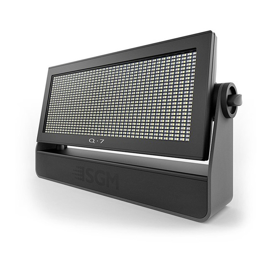
INSTALLATION STANDARD FIXTURE IDENTIFICATION AND TERMINOLOGY A: Q-7: 1000 RGB + 1000 White LEDs Q-7W: 1000 White LEDs B: Q-7 Tilt lock C: Cooling fans D: DMX in and out E: Wireless antenna socket (POI n/a) F: RFID Antenna (POI n/a) -
Page 9: Unpacking
All SGM fixtures have locking points in the base for installation and rig- Ø 18 mm ging. In both standard and POI fixtures, the distance between the [ 0,7in ] points from center to center is always 106 mm. -
Page 10: Rigging Process Using Sgm Omega Brackets
M-10 key until they are fully attached to the base. Figure 3 : Installing the Q-7 4. Hang the fixture on a truss or other structure. Tighten the clamp/bracket. 5. Verify that there are no combustible materials, cables, or surfaces to be illuminated within 0.3 m (12 in.) of the fixture. -
Page 11: Tilt Lock
WARNING! ALWAYS SECURE AN ELEVATED FIXTURE WITH A SAFETY WIRE. ALWAYS USE A SAFETY WIRE OF A GRADE AISI 316 STEEL. MAKE SURE THE SLACK OF THE SAFETY WIRE IS AT A MINIMUM. NEVER USE THE YOKE/HAN- DLE FOR SECONDARY ATTACHMENT. Fasten a safety wire (not shown) between the load-bearing support structure and the safety wire attachment point on the device. -
Page 12: Connecting Power
IP-rated XLR connectors suitable for outdoor use. Terminate the DMX out cable of the last fixture in the data link with a 120 ohm DMX termination. Note that SGM fixtures provide a passive DMX Thru signal as DMX Out, instead of an active output signal. PLEASE NOTE! FOR POI VERSIONS, PLEASE REFER TO “INSTALLATION POI FIXTURE”... -
Page 13: Attaching The Crmx™ Wireless Antenna
ATTACHING THE CRMX™ WIRELESS ANTENNA The CRMX™ wireless receiver antenna is an included accessory and is recommended for long-range wireless opera- tion. Before connecting the wireless receiver, ensure that there is no DMX cable connected to the fixture. For long-range operation, replace the factory default cone antenna with the supplied wireless CRMX™... -
Page 14: Installation Poi Fixture
INSTALLATION POI FIXTURE IDENTIFICATION AND TERMINOLOGY A: Q-7: 1000 RGB + 1000 White LEDs Q-7W: 1000 White LEDs B: Q-7 POI Tilt lock C: Cooling fans D: DMX in and out LED indicator (POI only) GORE-TEX membrane Power connection Holes for Omega bracket / M-10 screws (x4) Safety wire attachment point Illustrations might vary from received products. -
Page 15: Unpacking
PLEASE NOTE! POI FIXTURES SHOULD BE PRE-SET WITH ANY CUSTOM PROGRAMMING BEFORE INSTALLA- TION. ALTHOUGH MOST FUNCTIONS ARE POSSIBLE TO BE SET VIA RDM ONCE MOUNTED IN POSITION, IT IS EASIER TO DO CONFIGURATION AND ANY TROUBLESHOOTING BEFORE MOUNTING IS COMPLETE. UNPACKING Unpack the device and inspect it to ensure that it has not been damaged during transport. -
Page 16: Connecting Temporary Signal
CONNECTING TEMPORARY SIGNAL The fixture is compatible with DMX512 (ANSI E1.11 – 2008) only. It can be connected using either the SGM POI up-load- er cable, or via the fixture’s built-in CRMX wireless receiver system. STEP 1: Download and install the SGM RDM Addressing tool. -
Page 17: Settings And Fixture Defaults
POI fixture. But on POI, these settings are changed through the Addressing Tool. Figure 13: SGM Addressing tool STEP 1: Launch SGM RDM Addressing Tool. Click Full Discovery and look for the green light to illuminate on the fixture. If the green light does not appear, cycle power or refer to troubleshooting. -
Page 18: Wireless Data Connection
Figure 14: POI Spanner STEP 1: Using a SGM magnetic spanner tool, place the magnet close to the LED indicator, and wait for 3 seconds. The LED indicator will blink orange for 1-2 seconds, before switching to static green again. The fixture can now be paired to a new transmitter. -
Page 19: Mounting
MOUNTING All SGM POI fixtures have M10 size attachment points to mount the supplied brackets or directly to a structure. The POI wash fixture may be installed in any orientation and it might take up to two brackets per fixture. Depending on the structure, please use appropriate and secure methods for mounting the Omega brackets. -
Page 20: Flat Bracket Attachment
FLAT BRACKET ATTACHMENT M10 Countersunk Bolts 8mm or smaller screw or bolt to structure 8mm or smaller screw or bolt to structure Flat Bracket Fixture OMEGA BRACKET ATTACHMENT 13mm / 0.5in hole diameter for attachment point M10 Stainless Steel Bolts POI Omega Bracket Fixture Product Version 1.0 | Revision F | Released 2023-02-20... -
Page 21: Universal Bracket Attachment
UNIVERSAL BRACKET ATTACHMENT Using a bolt through this slot, M10 Countersunk Bolts the fixture will rotate around its center point, always use 2 bolts with washers. Using a bolt through this slot, the fix- ture will rotate around its center point, always use 2 bolts with washers. -
Page 22: Wall Bracket Attachment
WALL BRACKET ATTACHMENT Medium 6/8 Series Attach and align the bracket to a surface. The shorter side of the bracket is the side that attaches to a wall surface. There are two slots provided to align the bracket. Using appropriate fas- teners, align and level the bracket. -
Page 23: Poi Tilt Lock
POI TILT LOCK The fixture can be tilted in any orientation. To adjust the tilt angle in POI fixtures: • Loosen the two tilt lock kobs (one on each side) by turning them counter-clockwise using the small pig-nose key. Knobs are loosened by turn- ing counter-clockwise. -
Page 24: Permanently Connecting Power & Data
DMX signal, like to RS-485 signal protocol. DMX in and DMX out are in the same cable. See more in figure above about the SGM POI DMX cable. For permanent installations, have a qualified electrician wire the mains cable directly to a suitable branch circuit. -
Page 25: Wireless
In order to do so, make sure the fixture is powered on before taking the following steps: • STEP 1: Using a SGM magnetic spanner tool, place the magnet close to the LED indicator, and wait for 3 sec- onds. The LED indicator will blink orange for 1-2 seconds, before switching to static green again. The fixture can now be paired to a new transmitter. -
Page 26: User Interface
USER INTERFACE The fixture can be set up by using the control panel and OLED multi-line display on fixture’s head or through RDM. PLEASE NOTE! IN POI VERSIONS THE DISPLAY IS REPLACED BY AN INDICATOR LIGHT. THE ADJUSTMENTS ARE MADE THROUGH RDM. SEE “POI PERMANENT OUTDOOR INSTALLATION”... -
Page 27: Display
DISPLAY OPERATIONAL MODE (A) Displays the current mode (quick color, stand-alone, or DMX mode). The fixture is set by default to be controlled in DMX mode. 6CH CTC MODE (107) DMX ADDRESS (B) A - Operational mode Displays the current DMX address. The DMX address is al- B - DMX address tered directly from this view. -
Page 28: Configuring The Device For Dmx Control
CONFIGURING THE DEVICE FOR DMX CONTROL ABOUT DMX The fixture can be controlled using signals sent by a DMX controller on a number of DMX channels. DMX is the USITT DMX512-A standard, based on the RS-485 standard. The signal is sent as DMX data from a console (or a controller) to the fixtures via a shielded twisted pair cable designed for RS-485 devices. -
Page 29: Full Color Calibration And Color Temperature Correction (Q-7 Only)
FULL COLOR CALIBRATION AND COLOR TEMPERATURE CORRECTION (Q-7 ONLY) • Most DMX channels: Possibility to choose between raw or white-calibrated color (6500K default) via the Control Menu (SETTINGS → WHITE CALIBRATED). • RGB DMX modes: Features full color calibration (irrespective of current color setting) when 2 or 3 colors are mixed, to ensure uniform color mixing between products. -
Page 30: Setting A Static Color Manually
SETTING A STATIC COLOR MANUALLY The standard fixture can be configured to display a predefined and static color. To set up a static color select ENTER → MANUAL → QUICK COLOR. Note that, once the MANUAL → QUICK COLOR settings are changed, the fixture will be set, by default, to automatical- ly start in quick color mode whenever it is powered on. -
Page 31: Fixture Properties
Q-7 Series offers the ability to adjust the refresh rate (frequency) in order to achieve flicker-free performance. In the Q-7 menu, go to SETTINGS → REFRESH RATE. Here you are able to set the refresh rate (frequency) of the LEDs to be: •... -
Page 32: Control Menu
Wireless Signal Strength Check wireless signal strengh Startup Mode Select Startup Mode Default operating mode when fixture is powered on: 1. Quick Color 2. Stand-alone 3. DMX (factory default) Startup Program Stand-alone program 1, 2 or 3. Only used if the startup mode is set to “stand-alone”. Program 1 is default. Dimming Curve Linear Provide equal resolution dimming from 0-100%. Gamma Corrected Provide high-resolution dimming at low levels. White Calibrated Calibrated Enable white calibrated color. (Q-7 only) Enable raw color. Flip Display Disable [X] / [ ] Select normal control panel display. Enable [X] / [ ] Flip control panel display. Display Saver Display Dim Dim the OLED display when the control panel is not in use. Display Off Turn off the OLED display when the control panel is not in use. Fan Mode Standard [X] / [ ] Adjust fan speed relative to internal fixture temperature. Silent [X] / [ ] Low fan speed for quiet operation. - Page 33 Dimming optimized Set the LED’s to a dimmer optimized default. (factory default). (continued) See “Setting the LED refresh rate (Frequency)” on page 13 for details. High frequency opti- Set the LED’s to a high frequency optimized default. mized See “Setting the LED refresh rate (Frequency)” on page 13 for details. Custom value frequency Set a custom frequency (refresh rate) for the LED’s. See “Setting the LED refresh rate (Frequency)” on page 13 for details. Factory Default Reset the fixture to factory default settings. Service Pin Contact your SGM dealer or SGM support to request the service pin. Service use only. Service Menu Only accessible when service pin has been entered. Service use only. Manual Quick Color Red (Q-7) 1 → 255 Press enter to set fixture to static quick color startup mode (red mix). Green (Q-7) 1 → 255 Press enter to set fixture to static quick color startup mode (green mix). Blue (Q-7) 1 → 255 Press enter to set fixture to static quick color startup mode (blue mix). White (Q-7 / Q-7 W) 1 → 255 Press enter to set fixture to static quick color startup mode (white mix). Run Program 1, 2 or 3 Select program (1, 2 or 3) to run internal sequence. Stop Program Stop current running internal sequence or Quick Color. Master/Slave Master Slave Set fixture to operate as Master or Slave fixture.
-
Page 34: Rdm
SUPPORTED RDM FUNCTIONS he Q-7 Series features support for various RDM functions. RDM (Remote Device Management) is a protocol enhancement to USITT DMX512 that allows bi-directional commu- nication between the fixtures and the controller over a standard DMX line. This protocol will allow configuration, sta- tus monitoring, and management. -
Page 35: Accessories
The Q-7 Series have available an optional floorstand, ideal when there is a frequent need of changing the position of the fixture between hang- ing and standing. The Q-7 floorstand it is easy to mount or remove, simply by the use of 1/4 turn fasteners. Figure 26 : Floorstand... -
Page 36: Anti-Glare Shields
Figure 29: SGM Vacuum Test Kit USB - XLR UPLOADER CABLE The SGM USB to DMX cable is an accessory used mainly to up- date the fixture with the latest SGM firmware. See below how to update the fixture with the latest firmware. -
Page 37: Firmware Updates
UNDER THE RESPECTIVE PRODUCT AT WWW.SGMLIGHT.COM. CLEANING SGM fixtures with IP65 or IP66-rating do not need any cleaning procedures inside the fixture. However, cleaning the front lens may be needed to achieve the maximum light output after exposure to dust, sand, or dirt. The exterior housing can also be cleaned to get a better look. -
Page 38: Troubleshooting
The minimum values are out of calibration. Contact your local SGM dealer or support@ sgmlight. The SGM Calibration Data set has been lost. Contact your local SGM dealer or support@ sgmlight. Product Version 1.0 | Revision F | Released 2023-02-20... -
Page 39: Fixtures And Accessories
Half Anti-Glare Shield, P-5, Q-7, i-5 Series, BL / WH ....... -
Page 40: Support Hotline
SUPPORT HOTLINE SGM offers 24/7 technical support. Worldwide: +45 3840 3840 US: +1 407-242-6217 support@sgmlight.com APPROVALS AND CERTIFICATIONS Conforms to ..............2014/35/EU: Low Voltage Directive Conforms to . -
Page 41: User Notes
USER NOTES Product Version 1.0 | Revision F | Released 2023-02-20... - Page 42 SGM LIGHT A/S Sommervej 23 8210 Aarhus V Denmark Tel: +45 70 20 74 00 info@sgmlight.com www.sgmlight.com Product Version 1.0 | Revision F | Released 2023-02-20...
Need help?
Do you have a question about the Q-7 and is the answer not in the manual?
Questions and answers