Table of Contents
Advertisement
Advertisement
Table of Contents

Subscribe to Our Youtube Channel
Related Manuals for SGM Pilot 2000


Summary of Contents for SGM Pilot 2000
-
Page 2: Table Of Contents
PILOT 2000 USER GUIDE To Clear All the Memory....................3 Operations Keyboard Section...................5 Setup button:......................5 Copy button:......................5 Enter button:......................5 Play button:........................5 Utility Keyboard Section....................5 Extra button:......................5 Lamp button:......................5 Reset button:......................6 Page Button........................6 Page button:......................6 Programming Keyboard Section..................6 Store button:......................6 Edit button:........................6 Levels button:......................6... - Page 3 To set the Control Type for each parameter:............22 Synchronization of the Desk with RS232................24 CHANNEL ON......................24 CHANNEL OFF.......................24 REGISTER CHANGE....................24 ALL CHANNEL OFF....................24 PAGE CHANGE......................24 DEVICE SELECT....................24 Connection of the RS -232 CABLE for Pilot 2000:..........25 SMPTE...........................25 SGM A/S · Ver. 2.03...
-
Page 4: To Clear All The Memory
4.Type in 121297 fast (within 4 seconds),by using the buttons 1-20 of the Multifunction Keyboard. N.B. this will also delete all the scanners details that have been programmed in, excluding the existing SGM fixtures that are part of the permanent software of the board. SGM A/S · Ver. 2.03... -
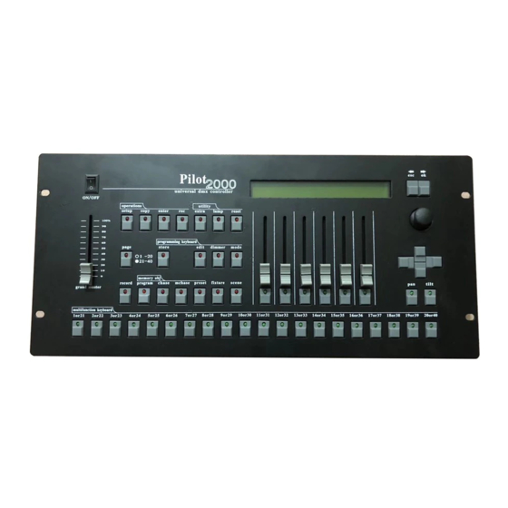
Page 5: Operations Keyboard Section
Utility Keyboard Section The key buttons and the white printing identify this section. This section of the Pilot 2000 makes special functions such as Extra, Lamp and Reset, immediately available: these operate directly on the fixtures (switching the lamp on and off), the intelligent fixtures (remote Reset) and the controls sent to special units such as smoke machines or centerpieces (Extra channels). -
Page 6: Reset Button
PILOT 2000 USER GUIDE Reset button: It enables the remote Reset control of a fixture. Furthermore it can be used as follows: Psycho: when put on zero; the light output of all the dimming channels set on a given sound frequency band Preset: when put on zero;... -
Page 7: Memory Object Keyboard Section
PILOT 2000 USER GUIDE Memory Object Keyboard Section The key buttons and the white printing identify this section. This section of buttons is used to select the 4 elements that make up the Memory Objects (Program, Chase, Psycho and Preset). Once they've been programmed, these elements must be entered in the Memories in order to be run. -
Page 8: Grand Master
PILOT 2000 USER GUIDE Grand Master The Pilot 2000 has a general output level control, used to adjust the overall level of all the "dimmer" channels, whether they are of the traditional type or of intelligent fixtures. The value is shown as a percentage, with a range of 0 - 100%. -
Page 9: To Select A Chase
PILOT 2000 USER GUIDE To select a Chase: 1. Press Chase key 2.Press a button of the MFK according to the chase to be created or modified Up to 4 Chases at the same time can be run in one memory. -
Page 10: To Set And Store A Group
PILOT 2000 USER GUIDE To set and store a group: 1.Press and hold down the Unit Key. The display will show “select other units to make a group” and the light gray buttons below the 6 faders become the 6 storable groups;... -
Page 11: Patching
This function allows operators to decide how many DMX channels must be assigned to the dimmer channels. Pilot 2000 can control a minimum of 6 channels up to 192 channels, divided into 32 pages on the display. To avoid patch conflict, set the Total Dimmer Channels before to patch the Extra channels and Unit channels. -
Page 12: Patching Units
PILOT 2000 USER GUIDE Patching Units WARNING! To avoid patching conflict, don’t let the Unit Channels to overlap the Dimming channels or the Extra Channels 1. Press the Setup button. 2. Scroll with the up/down arrows until “Unit Patch” appears on the display. -
Page 13: Manual Use Of The Unit
PILOT 2000 USER GUIDE Manual use of the Unit A unit can be manually controlled at any time whether a Program is enabled or not. Into a running Program, it’s possible to control only some desired fixture’s channels while the other channels will follow the settings plotted in the program. -
Page 14: Programming
PILOT 2000 USER GUIDE Programming To program a Preset: 1. Select a Memory 2. Press Preset button; 3. Press a button 1-20 (21-40) of the MFK according to the preset to be created 4. Press Edit key (red LED on the Edit button and the green LED of the MFK preset will blink) 5. -
Page 15: To Edit A Program
PILOT 2000 USER GUIDE To edit a Program: 1.Select a Memory 2.Press Program key 3.Press a button 1-20 (21-40) of the MFK according to the program to be created 4.Press Edit Key 5.Press right arrow of the scroll buttons (located on the right of the display) 6.Select Edit Step from the edit menu... -
Page 16: To Set The Length Of A Program Or Chase
PILOT 2000 USER GUIDE To set the Length of a Program or Chase: The desk automatically increases the steps of a Program or Chase. By the way, if the length need to be changed, proceed as follows: 1. Select a Memory 2. -
Page 17: Times Of A Psycho Or Preset
Operators often have to limit a fixture's scanning area to adapt stored programs to stage situations, which often change. With a view to this, Pilot 2000 allows to control the 20 different scanning areas for each fixture (obviously only scanners and moving head units) which operators have at their disposal. -
Page 18: To Test A New Working Area
PILOT 2000 USER GUIDE 5. With the Left/Right buttons select the SET 1 field and use the fader below to choose one of the 20 available scanning areas (SET 1 to SET 20) 6. To modify the scanning area, press the light gray button under the one of the 4 small corner symbols, showed on the display, then move the joystick to the required new corner. -
Page 19: Internal Library
Reset. 11. Dip-Switch Config: set here the quantity of dip-switches the fixture uses to assign the start address. SGM’s fixtures use 9 switch dip-switches 12. Beam Find Value: set here to open position those channels which allows the operator to see the fixture’s beam when setting the Working Area (iris open;... -
Page 20: To Insert A New Fixture Configuration Into The Pilot's Library
PILOT 2000 USER GUIDE To insert a new fixture configuration into the Pilot’s library: 1. Press the Menu button. 2. Scroll with the up/down arrows until “Internal Library” appears on the display. 3. Press the right-hand Scroll button to enter the menu 4. -
Page 21: To Assign The Dmx Channels To The Parameters
PILOT 2000 USER GUIDE 3b) Effect String: allows to write the parameter’s name on top of each scann control fader. 1. By using the up/down arrows replace the “--------------------------------------“ which appear on display with the letters required to insert a short name describing each fixture’s parameter. -
Page 22: To Set The Hard/Soft Cross
2. Press the right-hand Scroll button to enter the menu. 3. By using the up/down arrow, set here the quantity of dip-switches the fixture uses to assign the start address. SGM’s fixtures use 9 switch dip-switches. 4. Press the left-hand Scroll button to escape the menu. - Page 23 CONTROL CHANGE 7Bh 0h; There is the possibility to control more than one desk via Midi simply using a PILOT 2000 desk like a Master and all the others as a Slave. There are no special settings to do on the Master desk, just plug the Midi cable and play.
-
Page 24: Synchronization Of The Desk With Rs232
PILOT 2000 USER GUIDE Synchronization of the Desk with RS232 The Pilot 2000 can use the serial interface for connection to outboard devices, which synchronize its operation. By means of a computer, it is possible to send commands via the RS232 signal. -
Page 25: Connection Of The Rs -232 Cable For Pilot 2000
Either way, the time code ’word’ is the same. RECORDING AN SMPTE TRACK The SMPTE can be used on the Pilot 2000 in 2 ways: INTERNAL TIMING or EXTERNAL TIMING. In both cases, it is possible to record 20 tracks with a limit of 24576 “events”... - Page 26 EXTERNAL TIMING To use the Pilot 2000 as a slave of an SMPTE device, just connect it, through a 3 pin XLR cable, to an SMPTE source (video recorder, computer, ...) and then proceed as follows: 1.
Need help?
Do you have a question about the Pilot 2000 and is the answer not in the manual?
Questions and answers