
Related Manuals for SGM P-3


Summary of Contents for SGM P-3
- Page 1 USER MANUAL PRELIMINARY Product Version 1.0 | Document Revision A | Released 2023-10-19...
-
Page 2: P-3 Vision Dimensions
All dimensions in millimetres and inches. Drawing not to scale This manual covers installation, use, and maintenance of the P-3 SGM Series. A digital version is available at www.sgmlight.com or upon request via support@sgmlight.com. The information in this document is subject to change without notice. -
Page 3: P-3 Wash Dimensions
P-3 WASH DIMENSIONS 11,417in 290mm 11,024in 280mm 6,063in 154mm 9,915in 251,85mm 6,618in 168,1mm 180° 9,892in 251,25mm 6,618in 168,1mm All dimensions in millimeters and inches. Drawing not to scale Product Version 1.0 | Revision A | Released 2023-10-19... -
Page 4: Table Of Contents
CONTENT P-3 VISION DIMENSIONS P-3 WASH DIMENSIONS 6 SAFETY INFORMATION 7 BEFORE INSTALLING THIS PRODUCT 8 OVERVIEW 8 Fixture Types 8 Cabling on Wash and Vision 8 Control Options 9 INSTALLATION P-3 9 Identification and terminology of P-3 Vision 10 Identification and terminology of P-3 Wash 11 Unpacking 11 Application considerations... - Page 5 22 CONFIGURATION WITH DMX/RDM ADDRESSING TOOL 23 FIXTURE PROPERTIES AND DEFAULT SETTINGS 23 Individual Fixture Settings 23 LED Engine 23 Beam Angle 24 RDM 24 Supported RDM functions 24 Sensors 25 CONTROLLING P-3 VISION 25 Operation from a single controller 26 Operation from two controllers using Hybrid Mode 29 ACCESSORIES 29 Arraying bracket 29 Filter frame 30 MAINTENANCE 30 Firmware Updates 31 ...
-
Page 6: Safety Information
WARNING! READ THE FOLLOWING SAFETY PRECAUTIONS CAREFULLY BE- FORE UNPACKING, INSTALLING, POWERING OR OPERATING THE DEVICE. SGM fixtures are intended for professional use only. They are not suitable for household use. Les fixtures SGM sont impropre à l’usage domestique. Uniquement à usage professionnel. -
Page 7: Before Installing This Product
BEFORE INSTALLING THIS PRODUCT VISUAL INSPECTION All users of the SGM fixtures should regularly clean those parts of the fixture directly exposed to the elements, such as the external housing and front lenses. Additionally, all owners of the SGM fixtures must periodically check the external housing of the fixture for structural breaks, deteri- oration, cracked lenses, or loose screws. -
Page 8: Overview
OVERVIEW The P-3 series of fixtures are designed to provide even and powerful washes over various flat surfaces such as stages and building facades. The range features multiple beam angles, LED engines and control protocols. P-3 is an exterior, IP66 rated product intended for permanent or temporary mounting. -
Page 9: Installation
INSTALLATION P-3 IDENTIFICATION AND TERMINOLOGY OF P-3 VISION A: 24 x RGBW LEDs B: 28 x RGB pixels C: GORE-TEX membrane D: Cooling fans E: Dehumidifier F: Control Panel G: Handle H: Tilt Lock I: Power In/Out J: Ethernet In/Out... -
Page 10: Identification And Terminology Of P-3 Wash
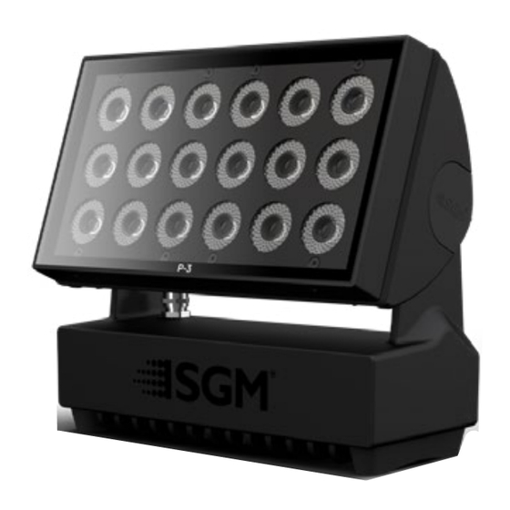
IDENTIFICATION AND TERMINOLOGY OF P-3 WASH A: 24 x RGBW LEDs B: GORE-TEX membrane C: Cooling fans D: Dehumidifier E: Control Panel F: Handle G: Tilt Lock H: Power In/Out I: Ethernet In/Out J: DMX In/Out K: Holes for Omega bracket / M-10 screws (x2) L: Safety wire attachment point Product Version 1.0 | Revision A | Released 2023-10-19... -
Page 11: Unpacking
Testing the fixture for proper function is also recommended. During testing, configuration and addressing can be done. The P-3 is an addressable product and is most efficiently configured before installation. This is especially true in installations where the fixtures will be in inaccessible areas. -
Page 12: Rigging
All SGM fixtures have locking points in the base for installation and rigging. In both standard and POI fixtures, the distance between the points from center to center is always 106 mm. Standard versions include 1/4 turn fasteners to mount SGM omega brackets. -
Page 13: Omega Bracket
0.3 m (12 in.) of the fixture. Step 6. Check that there is no risk of the head/yoke colliding with other fixtures or structures. Figure 3 : Installing the P-3 Product Version 1.0 | Revision A | Released 2023-10-19... -
Page 14: Safety Wire
SAFETY WIRE Fasten a safety wire (not shown) between the load-bear- ing support structure and the safety wire attachment point on the device. The safety cable (not included in the package) must: • Bear at least 10 times the weight of the device (SWL). -
Page 15: Arraying
PLEASE NOTE! APPLICABLE TO P-3 VISION AND WASH VARIANTS ONLY. The P-3 Vision and Wash are designed to work with an arraying bracket which locks the fixtures together in x and y axis. This bracket aligns the fixtures only, they are not designed to be self-supporting. -
Page 16: Power And Data
P-3 VISION AND WASH POWER The power input required is 100–277 V, 50/ 60 Hz AC mains power supply, and draws a maximum of 360 Watts (P-3 Vision) or 330W (P-3 Wash) . Both are connected to power via “Powercon” type connectors. Power plug is as per local code. -
Page 17: Dmx
For outdoor installations, use only IP65-rated XLR connectors suitable for outdoor use. Terminate the DMX out cable of the last fixture in the data link with a 120-ohm DMX termination. PLEASE NOTE! SGM FIXTURES PROVIDE A PASSIVE DMX THRU SIGNAL AS DMX OUT, INSTEAD OF AN ACTIVE OUTPUT SIGNAL. -
Page 18: User Interface
USER INTERFACE The fixture can be set up by using the control panel and OLED multi-line display on fixture’s head or through RDM. The OLED display shows the current status and menu of the fixture. It is used to configure individual fixture settings and read error messages. -
Page 19: Display
DISPLAY OPERATIONAL MODE (A) Displays the current mode (quick color, stand-alone, or DMX mode). The fixture is set by default to be controlled in DMX mode. FIXTURE UNIVERSE (B) Displays the current fixture universe. The universe is al- tered directly from this view. DMX ADDRESS (C) Figure 10: Display Displays the current DMX address. -
Page 20: Configuration
CONFIGURATION P-3 Vision and Wash are configured using either the user interface or SGM software; the SGM software, the SGM RDM Addressing Tool. This software is Windows® PC based and connects to the fixtures via DMX512/RDM using the SGM USB uploader cable. -
Page 21: Manual Operation
MANUAL OPERATION The standard fixture can be configured to display a predefined and static color. To set up a static color select ENTER → MANUAL → QUICK COLOR. Note that, once the MANUAL → QUICK COLOR settings are changed, the fixture will be set, by default, to automatical- ly start in quick color mode whenever it is powered on. -
Page 22: Configuration With Dmx/Rdm Addressing Tool
Fig 15: RDM Addressing Tool STEP 1: Launch SGM RDM Addressing Tool. Click Full Discovery and look for the fixture to show in the table. STEP 2: Select the standard settings tab and enter a DMX address and a personality/mode of operation. These modes must match the control mode in the controller which will control the fixture. -
Page 23: Fixture Properties And Default Settings
SETTINGS → FAN MODE in the menu. LED ENGINE All variants in the P-3 Series feature 18 high-power multichip LEDs. These are either RGBW or Tunable White LEDs, divided into 3 individually controllable segments. -
Page 24: Rdm
SUPPORTED RDM FUNCTIONS RDM (Remote Device Management) is a protocol enhancement to USITT DMX512 that allows bi-directional commu- nication between the fixtures and the controller over a standard DMX line. This protocol will allow configuration, sta- tus monitoring, and management. A RDM controller is needed to get control over the supported parameters. See the tables below for supported RDM functions. -
Page 25: Controlling P-3 Vision
OPERATION FROM A SINGLE CONTROLLER The P-3 Vision can be controlled from either one or two controllers at the same time. When Hybrid Mode is disabled, the fixture will behave as a standard lighting fixture in the sense that it will only receive and use data from a single controller. -
Page 26: Operation From Two Controllers Using Hybrid Mode
How to use the Crossfade channel? The Crossfade channel is a DMX channel that is present as the last one in every P-3 Vision DMX Mode. It allows the lighting operator to choose whether the Vision Section outputs RGB content from the lighting controller or the media server or a mix of both. - Page 27 Hybrid Mode enabled and the crossfade channel at 0 LIGHTING CONTROLLER Fixture profile: 13 Channel CTC WASH SECTION VISION SECTION HYBRID DMX / Art-Net / sACN Art-Net / sACN Content Fixture profile: 84 Channel RGB (28 x RGB 8 bit) MEDIA SERVER Fig 17: Lighting controller Product Version 1.0 | Revision A | Released 2023-10-19...
- Page 28 Hybrid Mode enabled and the crossfade channel at 255 LIGHTING CONTROLLER Fixture profile: 13 Channel CTC WASH SECTION VISION SECTION HYBRID DMX / Art-Net / sACN Art-Net / sACN Content Fixture profile: 84 Channel RGB (28 x RGB 8 bit) MEDIA SERVER Fig 18: Lighting controller Product Version 1.0 | Revision A | Released 2023-10-19...
-
Page 29: Accessories
Figure 19 : Arraying bracket FILTER FRAME The P-3 filter frame is designed to snap on to the front of the P-3 front bezel. Filters are in- terchangeable within the frame and are changed by snapping the filter into the frame first, then attaching the frame to the P-3. -
Page 30: Maintenance
MAINTENANCE FIRMWARE UPDATES The latest firmware, manuals and the SGM Network Admin tools are all available for free download a www.sgmlight. com. The SGM Light firmware tool is used to update firmware: Fixture firmware can be identified in two different ways: Standard Fixture •... -
Page 31: Cleaning
Figure 26: SGM Uploader cable POI CLEANING SGM fixtures with IP65 or IP66-rating do not need any cleaning procedures inside the fixture. However, cleaning the front lens may be needed to achieve the maximum light output after exposure to dust, sand, or dirt. The exterior housing can also be cleaned to get a better look. -
Page 32: Troubleshooting
The minimum values are out of calibration. Contact your local SGM dealer or support@ sgmlight. The SGM Calibration Data set has been lost. Contact your local SGM dealer or support@ sgmlight. Product Version 1.0 | Revision A | Released 2023-10-19... -
Page 33: Fixtures And Accessories
FIXTURES AND ACCESSORIES The fixture can be used with a variety of accessories. Contact your local SGM dealer to get the latest pricing and news about available accessories. PLEASE NOTE! THE LIST BELOW IS SUBJECT TO CHANGE WITHOUT NOTICE. ORDERING INFORMATION P-3 Vision, Std, BL ...................................... -
Page 34: Support Hotline
SUPPORT HOTLINE SGM offers 24/7 technical support. https://sgmlight.com/about-sgm/contact-us APPROVALS AND CERTIFICATIONS Conforms to ..............2014/35/EU: Low Voltage Directive Conforms to . -
Page 35: User Notes
USER NOTES Product Version 1.0 | Revision A | Released 2023-10-19... - Page 36 SGM LIGHT A/S Sommervej 23 8210 Aarhus V Denmark Tel: +45 70 20 74 00 info@sgmlight.com www.sgmlight.com...
Need help?
Do you have a question about the P-3 and is the answer not in the manual?
Questions and answers