Table of Contents
Advertisement
Quick Links
Product Version 1 | Manual Revision E | Released 2023-09-19
This manual covers installation, use, and maintenance of the SGM G-7 Beast. A digital version is available at www.
sgmlight.com or upon request via support@sgmlight.com. The information in this document is subject to change
without notice. SGM and all affiliated companies disclaim liability for any injury, damage, direct or indirect loss, conse-
quential or economic loss, or any other loss occasioned by the use of, inability to use, or reliance on the information
contained in this manual. The SGM logo, the SGM name, and all other trademarks in this document pertaining to
SGM services or SGM products are trademarks owned or licensed by SGM, its affiliates, and subsidiaries. This edition
USER
MANUAL
G-7 BEAST
applies to firmware version 2.23 or later.
English edition © 2023 SGM Light A/S ® .
Advertisement
Table of Contents

Subscribe to Our Youtube Channel
Related Manuals for SGM G-7 BEAST


Summary of Contents for SGM G-7 BEAST
- Page 1 Product Version 1 | Manual Revision E | Released 2023-09-19 This manual covers installation, use, and maintenance of the SGM G-7 Beast. A digital version is available at www. sgmlight.com or upon request via support@sgmlight.com. The information in this document is subject to change without notice.
-
Page 2: G-7 Beast Dimensions
G-7 BEAST DIMENSIONS G-7 BEAST STANDARD VERSION 349mm 433mm 13,75in 17,04in 70mm R156mm 2,75in 6,14in 604mm 23,77in 416mm 16,37in 249mm 323mm 9,80in 12,72in 387mm 370mm 15,25in 14,56in 432mm 17,01in 349mm 13,75in 70mm 2,75in 480mm 18,91in 604mm 578mm 23,77in 480mm 22,77in... -
Page 3: G-7 Beast Poi Version
G-7 BEAST POI VERSION 433mm 349mm 17,04in 13,75in 70mm 312mm 2,75in 12,28in 604mm 23,77in 416mm 16,37in 70mm 249mm 323mm 9,80in 12,72in 387mm 370mm 15,25in 14,56in 432mm 17,01in All dimensions in millimetres and inches. Drawing not to scale Product Version 1.0 | Revision E | Released 2023-09-19... -
Page 4: Table Of Contents
CONTENT 2 G-7 BEAST DIMENSIONS 2 G-7 Beast Standard version 3 G-7 Beast POI version 7 SAFETY INFORMATION 8 BEFORE INSTALLING THIS PRODUCT 9 INSTALLATION STANDARD FIXTURE 9 Parts identification and terminology 10 Unpacking 10 Application considerations 10 Transport handling 10 Rigging 11 Rigging process using SGM Omega bracket 12 Power requirements ... - Page 5 CONTENT 21 DMX Start Address (D) 21 DMX Mode (E) 21 Using the keyboard (F) 21 Display settings 22 CONNECTING TO A DMX CONTROL DEVICE 22 Connecting to a DMX control device 22 Connecting a wireless transmitter 22 Disconnecting a wireless transmitter 22 Signal priority 23 About DMX 23 DMX Start address 23 Setting the DMX address 23 DMX modes 23 CONFIGURING THE DEVICE FOR DMX CONTROL 24 G-7 BeaSt Connection diagram 25 USING STAND-ALONE OPERATION 25 ...
- Page 6 CONTENT 40 MAINTENANCE 40 SGM Vacuum Test kit 41 Cleaning 41 Maintenance Schedule G-7 41 firmware updates 42 Maintenance Notes 42 Cleaning 42 Ordering information 42 G-7 BeaSt accessories 42 G-7 BeaSt Consumables 43 APPROVALS AND CERTIFICATIONS 43 SUPPORT HOTLINE 44 USER NOTES Product Version 1.0 | Revision E | Released 2023-09-19...
-
Page 7: Safety Information
WARNING! READ THE FOLLOWING SAFETY PRECAUTIONS CAREFULLY BE- FORE UNPACKING, INSTALLING, POWERING OR OPERATING THE DEVICE. SGM luminaires are intended for professional use only. They are not suitable for househovld use. Les luminaires SGM sont impropre à l’usage domestique. Uniquement à usage professionnel. -
Page 8: Before Installing This Product
EXTERNAL CLEANING AND VISUAL INSPECTION OF THE FIXTURE All users of the SGM fixtures should regularly clean those parts of the fixture directly exposed to the elements, such as the external housing and front lenses. Additionally, all owners of the SGM fixtures must periodically check the external housing of the fixture for structural breaks, deteri- oration, cracked lenses, or loose screws. -
Page 9: Installation Standard Fixture
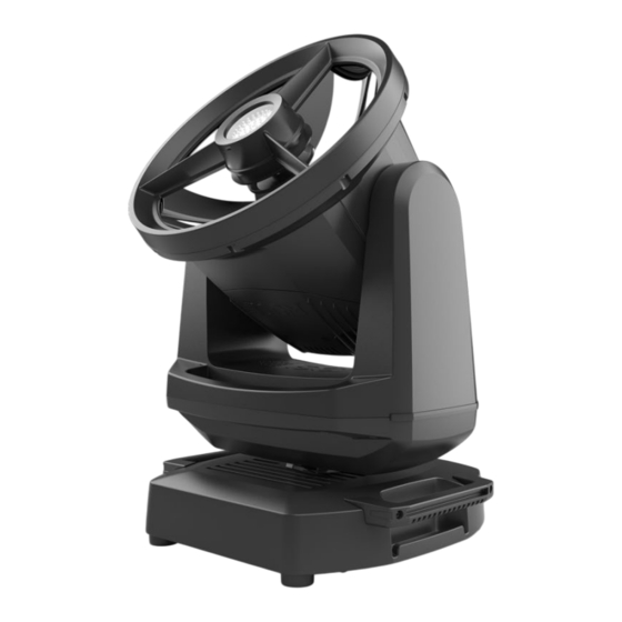
INSTALLATION STANDARD FIXTURE The G-7 BeaSt/ G-7 BeaSt POI is a fast, lightweight and mid-sized Beam Strobe moving head with high-output and low power consumption, designed for multiple applications, including when wireless operation is essential. The G-7 BeaSt features: An IP66 rated moving head with two separated white LED engines: a 6,500 K Beam and a 8,000 K Strobe Blinder*. -
Page 10: Unpacking
G-7 BeaSt includes 1/4-turn fastener cam locks to mount the omega brackets. For further details of the bracket dimensions contact SGM support. The G-7 BeaSt may be installed in any orientation, with or without base, on the ceiling or on a wall surface. Ø 18 mm... -
Page 11: Rigging Process Using Sgm Omega Bracket
3. Align an Omega bracket with two 1/4-turns in the G-7 BeaSt base. Insert the fasteners into the G-7 BeaSt base and turn both levers a 1/4-turn clockwise to lock, make sure that the levers are completely locked. Install the second Omega bracket. -
Page 12: Power Requirements
Never use the yoke or carrying handles for secondary attachment. POWER REQUIREMENTS The G-7 BeaSt can operate on any 100–240 V, 50/ 60Hz AC mains power supply. The maximum power consumption is 640 W. Connect the fixture to AC power by using the supplied 2 m (78 in.) power cable (fig.6) with IP connector or similar with a maximum of 20 A, to ensure... -
Page 13: Connecting Power
CONNECTING DATA The G-7 BeaSt is controlled by using a DMX control device, and it can be connected either by a DMX cable or via the fixture’s built-in CRMX wireless receiver system. If using a cabled DMX system, connect the DMX IN cable to the input connector (male 5-pin XLR plug), and the DMX OUT to the output connector (female 5-pin XLR plug), both connectors on the rear of the fixture’s base. -
Page 14: Installation Poi Fixture
INSTALLATION POI FIXTURE IDENTIFICATION AND TERMINOLOGY A: Front lens B: DMX in and out C: Power in and out D: Tilt Lock lock/unlock E: Led Indicator F: Yoke handles G: Pan lock/unlock H: Base handle (x2) I: Holes for Omega brackets (x8) J: Rubber feet (x4) K: Safety wire attachment point Illustrations might vary from received products. -
Page 15: Unpacking
Figure 8 : Connecting AC Power CONNECTING TEMPORARY SIGNAL SGM fixtures use the DMX 512 standard for communication. STEP 1: Download and install the SGM RDM Addressing tool. < https://sgmlight.com/products/rdm-addressing-tool > STEP 2: Connect the bare end data cable to the USB up-loader cable for POI fixtures as shown below STEP 3: Connect the USB up-loader cable for POI fixtures to a computer with a USB Type-A port. -
Page 16: Wireless Data Connection
DISCONNECTING A WIRELESS TRANSMITTER IN POI To disconnect the G-7 BeaSt POI from the currently paired wireless transmitter, simply hold the magnet for 3 seconds over the LED indicator. The LED indicator blinks orange for 1-2 seconds, switching later to green again. The fixture is now logged off. -
Page 17: Settings And Fixture Defaults
SETTINGS AND FIXTURE DEFAULTS The Addressing Tool is a windows based program designed to allow the user to configure the fixture through the RDM protocol. All settings on a standard fixture are available on a POI fixture. But on POI, these settings are changed through the Addressing Tool. -
Page 18: Mounting
M-10 nuts in the base. The G-7 Beast POI base has eight M-10 nuts that can be used for installation and rigging. The POI Omega Bracket (not included) or a customized bracket is needed to install the fixture. -
Page 19: Mechanical Tolerances And Recommended Use In Low Ambient
MECHANICAL TOLERANCES AND RECOMMENDED USE IN LOW AMBIENT TEMPERATURES Ambient temperature range for storage, start-up, and operation of G-7 Beast and G-7 Beast POI moving heads is described at www.sgmlight.com. All lighting fixtures have mechanical tolerances which can introduce unexpected results when in extreme temperatures. -
Page 20: Permanently Connecting Power & Data
• • The last fixture must always be fitted with a DMX termination plug to the fixture’s DMX out. • • SGM fixtures provide a passive DMX Thru signal as DMX out, instead of an active output signal. Product Version 1.0 | Revision E | Released 2023-09-19... -
Page 21: User Interface
USER INTERFACE The G-7 Beast can be set up by using the control panel located in the yoke of the fixture or through RDM. After being powered on,the G-7 Beast boots and resets. The current DMX start address and any status messages will be displayed thereafter. -
Page 22: Connecting To A Dmx Control Device
CONNECTING TO A DMX CONTROL DEVICE CONNECTING TO A DMX CONTROL DEVICE The G-7 Beast is controlled by using a DMX control device, and it can be connected either by a DMX cable or via the fixture’s built-in CRMX wireless receiver system. -
Page 23: About Dmx
For independent control, each G-7 BeaSt must be assigned its own DMX start address. For example, if the first G-7 BeaSt is set to 22ch DMX mode with a start DMX address of 10, the following G-7 BeaSt in the DMX chain should then be set to a DMX address of 32. -
Page 24: G-7 Beast Connection Diagram
100 - 240V AC 100 - 240V AC 50-60 Hz 50-60 Hz 640 W 640 W 120 Ohm +/- 5% 5 PIN XLR / DMX Cable Figure 18: Connecting DMX in G-7 Beast Product Version 1.0 | Revision E | Released 2023-09-19... -
Page 25: Using Stand-Alone Operation
USING STAND-ALONE OPERATION In stand-alone operation mode, the fixture is not running connected to a control device, but is preprogrammed with a series of up to 24 scenes, playing continuously in a loop (fig. 19). This program can be set up to run by default, whenever the fixture is powered on. -
Page 26: Control Menu
LEVEL 4 FUNCTION DMX MODE SELECT MODE Select DMX mode. INFO GENERAL INFO Product Displays product type. Displays SGM serial#. RDM Label Displays RDM Label. RDM ID Displays RDM ID. (Unique RDM ID for identifica- tion). SOFTWARE VER- Main Displays installed firmware version. - Page 27 LEVEL 1 LEVEL 2 LEVEL 3 LEVEL 4 FUNCTION SETTINGS WIRELESS DMX Enable [X] / [ ] Press ‘Enter’ to enable / disable - [X] / [ ]. Bridge DMX Log Off Press ‘Enter’ to log off wireless DMX. STATUS Signal Display the signal strength % of the connection.
-
Page 28: Factory Default
0 - 65535 TILT 0 - 65535 Please visit www.sgmlight.com, or contact your GOBO 1 ROT 0 - 65535 local SGM support for a complete DMX description GOBO 1 0 - 255 chart. STROBE DURATION 0 - 255 STROBE RATE... -
Page 29: Rdm
SUPPORTED RDM FUNCTIONS The G-7 Beast features support for various RDM functions. RDM (Remote Device Management) is a protocol enhancement to USITT DMX512 that allows bi-directional commu- nication between the fixtures and the controller over a standard DMX line. This protocol will allow configuration, status monitoring, and management. -
Page 30: Troubleshooting
Pan/tilt does not reset correctly. Calibration values are missing or incorrect. Contact SGM support or certified SGM service partner. Display is turned on, but the fixture Several causes. Contact your local SGM dealer or doesn't respond. -
Page 31: Errors
ERRORS The OLED display indicates whenever an error occurs. Note that lost steps in pan/tilt are corrected continuously and, therefore, do not show as an error, but are registered in the compensation count menu (cnt menu) instead. CONTROL PANEL DISPLAY MENU LOCATION DETAILED DESCRIPTION VIEW ERR - CW 1/CW 2/Gobo Sel Comp. -
Page 32: Fixture Properties
FIXTURE PROPERTIES MOTORIZED COLLIMATION The collimation system of the G-7 BeaSt is based on a small motorized convex reflector that bounces light from the LED engine to a fixed concave parabolic reflector (fig. 20). The movement of the controllable convex reflector modifies the focal point, allowing users to collimate the light. -
Page 33: High-Precision Pan And Tilt
COLOR WHEELS POSITION The G-7 BeaSt includes two independent colour wheels, each with 9 individual colours (see figure 21 and tables below for identification), and four modes: snap, split colour, and scroll mode. See our website www.sgmlight.com or contact SGM support for a complete dmx chart. - Page 34 Frost - Gobo G-7B 37005030-A Gobo wheel The G-7 BeaSt comes with 7 rotatable, indexable and exchangeable* gobos, including: • 2 split colours (open + cyan, orange + congo blue). • 3 glass aerial gobo patterns. • 1 frost filter.
-
Page 35: Opening The Fixture
OPENING THE FIXTURE Opening the fixture will only be necessary when changing gobos. Note that any removal/loosening or tampering with any component marked in the fixture will result in a void of warranty. WARNING! HANDLE COMPONENTS WITH CARE. ALWAYS WEAR SUITABLE GLOVES. - Page 36 Figure 26: The gobo is under the marked area PLEASE NOTE! DO NOT DETACH OR UNSCREW THE MODULE, AS IT WILL REQUIRE READJUSTMENT BY A CERTIFIED SGM TECHNICIAN TO MAINTAIN OPTIMAL OPERATION. Figure 27: Turn the gobo to the position which is to be...
- Page 37 (fig. 32). Clean the thermal sockets thoroughly before installing the new ones. Tilt Lock For more information on how to replace G-7 BeaSt gobos and to order thermal pads, please contact support@sgmlight.com Thermal pads order number: 21400060 2.
-
Page 38: Polytetrafluoroethylene Membrane
POLYTETRAFLUOROETHYLENE MEMBRANE The G-7 Beast includes an expanded polytetrafluoroethylene membrane, which allows the fixture to equalize air pressure. In order to vacuum test the fixture, the membrane has to be removed: 1. Turn the fixture off, disconnect it from mains and allow it to cool. -
Page 39: Module And Lens Warranty
MODULE AND LENS WARRANTY Due to the careful calibration of the cube and lens, it is not allowed to take these apart or remove from the fixture. If this is done, the warranty of the product will be void, and a significant loss of light quality might occur. If you change a gobo, make sure to follow "Gobo replace- ment"... -
Page 40: Maintenance
Figure 38: SGM Vacuum Test Kit USB - XLR UPLOADER CABLE The SGM USB to DMX cable is an accessory used mainly to update the fixture with the latest SGM firmware. See below how to update the fixture with the latest firmware. -
Page 41: Cleaning
To maintain adequate cooling, fans must be cleaned periodically. Whenever necessary, clean the G-7 Beast using a soft cloth dampened in water. For the front lens the front lens use regular glass cleaner. For thorough cleaning of plastic and metal exterior, use plastic cleaner such as SONAX PRO- FILINE Interior Plastic Cleaner. -
Page 42: Maintenance Notes
To maintain adequate cooling, fans must be cleaned periodically. Whenever necessary, clean the G-7 BeaSt using a soft cloth dampened in water. For the front lens the front lens use regular glass cleaner. For thorough cleaning of plastic and metal exterior, use plastic cleaner such as SONAX PRO- FILINE Interior Plastic Cleaner. -
Page 43: Approvals And Certifications
SUPPORT HOTLINE SGM offers 24/7 technical support hotline. Worldwide: +45 3840 3840 US: +1 407-242-6217 support@sgmlight.com APPROVALS AND CERTIFICATIONS Conforms to ..............2014/35/EU: Low Voltage Directive Conforms to . -
Page 44: User Notes
USER NOTES Product Version 1.0 | Revision E | Released 2023-09-19... - Page 45 SGM LIGHT A/S Sommervej 23 8210 Aarhus V Denmark Tel: +45 70 20 74 00 info@sgmlight.com www.sgmlight.com Product Version 1.0 | Revision E | Released 2023-09-19...
Need help?
Do you have a question about the G-7 BEAST and is the answer not in the manual?
Questions and answers