Table of Contents
Advertisement
Quick Links
Advertisement
Table of Contents

Related Manuals for Hytera HM68X


Summary of Contents for Hytera HM68X
- Page 1 HM68X Digital Mobile Radio User Manual Hytera Communications Corporation Limited...
- Page 2 Preface Welcome to the world of Hytera and thank you for purchasing this product. This manual includes a description of the functions and step-by-step procedures for use. To avoid bodily injury or property loss caused by incorrect operation, please carefully read the Safety Information Booklet before use.
- Page 3 Copyright Information Hytera is the trademark or registered trademark of Hytera Communications Corporation Limited (the Company) in the People's Republic of China (PRC) and/or other countries or areas. The Company retains the ownership of its trademarks and product names. All other trademarks and/or product names that may be used in this manual are properties of their respective owners.
-
Page 4: Table Of Contents
Contents Documentation Information ..........................3 1. Packing List ..............................5 2. Product Overview ............................6 2.1 Product Layout ............................6 2.2 Programmable Keys ..........................7 3. Installation ..............................8 3.1 Precautions ............................... 8 3.2 Tools ................................. 8 3.3 Parts ................................9 3.4 Procedure ............................... - Page 5 9.1 Basic Settings ............................19 9.1.1 Set Display ........................... 19 9.1.2 Set USB Path ..........................19 9.1.3 Set Language ..........................20 9.1.4 Enable LED Indicator ........................20 9.1.5 Reset a Radio ..........................20 9.2 Call Settings ............................20 9.2.1 Set Power Level ........................... 20 9.2.2 Set Talking Alias ...........................
- Page 6 11.3.4 Enable BT Location ........................30 11.4 One Touch Call/Menu ........................... 30 11.5 Roam ..............................31 11.6 Clarity Transmission ..........................31 11.7 Ignition Sense ............................31 11.8 Public Address ............................32 11.9 Priority Interrupt ............................ 32 11.10 XPT ..............................33 12.
-
Page 7: Documentation Information
Documentation Information This section describes the conventions and revision history of this document. Documentation Conventions Instruction Conventions Icon Description Indicates information that can help you make better use of your product. Indicates references that can further describe the related topics. Indicates situations that could cause data loss or equipment damage. - Page 8 Document Version Release Date Description September 2022 Initial release.
-
Page 9: Packing List
1. Packing List Unpack carefully and check that you have received the following items. If any item is missing or damaged, contact your dealer. Item Quantity (PCS) Item Quantity (PCS) Radio Power Cord (with fuse) Mounting Bracket Self-tapping Screw (4.8 mm x 20 mm) Locking Knob Self-tapping Screw (4 mm x 16 mm) Palm Microphone... -
Page 10: Product Overview
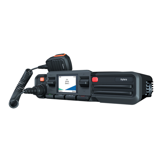
2. Product Overview 2.1 Product Layout Front Panel Channel/Navigation Key Volume Key Emergency Key (programmable) LED Indicator Aviation Port Answer Key OK/Menu Key Back/Z one Key End Key On-Off Key (programmable) (programmable) Rear Panel RF Antenna Connector Accessory Connector GPS Antenna Connector Power Inlet The GPS antenna connector is only used to install the GNSS antenna on radios with the Location feature. -
Page 11: Programmable Keys
Palm Microphone 2.2 Programmable Keys You can request your dealer to program the Emergency key, Answer key, and End key as shortcuts to assignable radio features. -
Page 12: Installation
3. Installation 3.1 Precautions Before installation, read the following guidelines carefully: Before installation, ensure that the vehicle power supply has a negative ground with the voltage of 13.6±15% V. Before installation, measure the length of screws protruding from the radio surface. During installation, drill the holes on the vehicle according to the screw length to avoid damaging the vehicle wires or other components. -
Page 13: Parts
3.3 Parts Part Name Part Name Radio Self-tapping Screw (4 mm x 16 mm) Locking Knobs Microphone Hanger Mounting Bracket GNSS Antenna Self-tapping Screw (4.8 mm x 20 mm) Power Cord (with fuse) Palm Microphone RF Antenna... -
Page 14: Procedure
The RF antenna is optional. The GNSS antenna is a standard accessory for radios with the Location feature. 3.4 Procedure Install the radio. Select a location on the vehicle. Hold the mounting bracket to the location, and then mark the mounting holes. Drill holes at the mounting holes. -
Page 15: Basic Operations
4. Basic Operations 4.1 Turn On or Off the Radio To turn on the radio, connect the radio to power supply or long press the On-Off key. To turn off the radio, long press the On-Off key. 4.2 Adjust Volume Toggle the Volume key up to increase the volume or down to decrease the volume. -
Page 16: Status Indications
5. Status Indications 5.1 LCD Icons Icon Radio Status The radio detects no signal. More bars indicate stronger signal. The radio works in low power mode. The radio works in high power mode. An accessory is connected. The GPS feature is enabled, and valid positioning data has been received. The GPS feature is enabled, but no valid positioning data has been received. -
Page 17: Led Indicators
Icon Radio Status The speaker is on. The radio works in silent mode. The radio works in profile 1. The radio works in profile 2. The radio works in profile 3. There is/are (a) new message(s). The inbox is full. There is/are (a) missed call(s). -
Page 18: Call Services
6. Call Services To ensure optimal voice quality on the receiving radio, keep the microphone 2.5 cm to 5 cm away from your mouth during speaking. 6.1 Group Call A group call is a call from an individual user to other group members. 6.1.1 Initiate a Group Call Through Preset Contact On the home screen, toggle the Channel/Navigation key to select a digital channel. -
Page 19: Receive A Private Call
Through Contact List Enter the Contact interface. Press the preprogrammed Contact List or Favorite Contact List key. On the home screen, go to Menu > Contact. Select a private contact. Press and hold the PTT key. Through Call Logs On the home screen, go to Menu >... -
Page 20: Receive An All Call
Select an all call contact. Press and hold the PTT key. Through One Touch Call/Menu Press the preprogrammed One Touch Call/Menu key, and then press and hold the PTT key. 6.3.2 Receive an All Call You can answer an all call without any operation. 6.3.3 End an All Call An all call ends when the caller releases the PTT key. -
Page 21: Message Services
7. Message Services Message allows you to send and receive text messages. 7.1 View a Message Upon message reception, press the OK/Menu key. On the home screen, go to Menu > Message, select a message, and then press the OK/Menu key. 7.2 Delete a Message On the home screen, go to Menu >... -
Page 22: Contacts
8. Contacts To view the contact information, do the following: On the home screen, go to Menu > Contact or press the preprogrammed Contact List key. Select a contact. -
Page 23: Settings
9. Settings You can set radio parameters including Basic Settings, Call Settings, and Security Settings. 9.1 Basic Settings 9.1.1 Set Display On the home screen, go to Menu > Settings > Basic Settings > Display, and then set any of the following: ... -
Page 24: Set Language
Option Description Operation Press the preprogrammed USB Path Only Rear Only the accessory connector can be used as the Switch key. Port USB path. 9.1.3 Set Language On the home screen, go to Menu > Settings > Basic Settings > Language. Toggle the Channel/Navigation key to select the display language. -
Page 25: Enable Dual Slot Data
If both the calling party and the called party enable the Auto Add Contacts and Send Alias features, the called party automatically adds the calling party to the contact list when receiving a call from the calling party. In the Talking Alias interface, select Auto Add Contacts. Press the OK/Menu key. -
Page 26: Lone Worker
When you enable Encryption, only the current channel is encrypted, and the channel remains to be encrypted after you switch the channel. 9.3.1.3 Select an Encryption Key On the home screen, go to Menu > Settings > Security Settings > Encrypt > Key List. Select an encrypt key. -
Page 27: Kill And Revive The Radio
Alarm Type Description The Horn & Lights feature is enabled or disabled based on the setting upon the last Alarm Re-Arm power-off. Non-Permanent Manual Re- The Horn & Lights feature must be enabled every time upon power-on. Permanent External Alarm The Horn &... -
Page 28: Set Audio Mode
9.4.3 Set Audio Mode Audio Mode adds gain to audio signals at high, medium, and low frequency, thus optimize the audio quality. On the home screen, go to Menu > Profiles > Setting > Audio Set > Audio mode. Select an audio mode. press the OK/Menu key. - Page 29 Option Description Operation Press the preprogrammed SPK Set The radio uses only the speaker of the audio Switch key. Only External accessory, such remote speaker microphone.
-
Page 30: Profiles
10. Profiles 10.1 Switch Profiles Profiles allows you to set the audio and alert tone of the radio for clear voice in various scenarios. The radio supports the following two profiles: General: applicable to common scenarios. Customized profiles: applicable to scenarios other than those in General. To switch profiles, do either of the following: ... -
Page 31: Radio Features
11. Radio Features 11.1 Scan 11.1.1 Enable Scan On the home screen, go to Menu > Scan > Scan On/Off, and then press the OK/Menu key. Press the preprogrammed Scan key. The radio scans according to the scan list preset for the current channel. During the scanning, the LCD displays , and the LED indicator flashes orange slowly. -
Page 32: Enable Positioning
11.2.1 Enable Positioning On the home screen, go to Menu > Position > Position On/Off Press the OK/Menu key. 11.2.2 View Position Local Position On the home screen, go to the Menu > Position > Position View. Press the OK/Menu key to view the position information of your radio (including longitude, latitude, speed, altitude, time, date, and the number of satellites). -
Page 33: Enable Gps Report
11.2.4 Enable GPS Report GPS Report allows the radio to report its location information to the control center. Press the preprogrammed GPS Report key, or you can consult your dealer to configure the GPS trigger, allowing the radio to automatically report the GPS data upon power-on/off, or according to the preset time or distance interval. Quick GPS Based on GPS standard time, Quick GPS divides the GPS upload time into several equal-length time slices. -
Page 34: Switch Bt Audio
Press the OK/Menu key. After the radio is connected to the BT device, the LED indicator of the radio flashes blue every 1.5 seconds. 11.3.2 Switch BT Audio With the BT device connected, press the preprogrammed BT Audio Switch key to switch the audio output device between BT earpiece and the radio. -
Page 35: Roam
Description Operation Initiate an alert call, radio check, remote monitor, revive, or Call/Menu key, and then press and kill service. hold the PTT key. Switch to a function menu or realize a function. 11.5 Roam Roam allows the radio to select base stations according to signal strength. This ensures seamless communication across sites or networks. -
Page 36: Public Address
Four types of ignition sense are listed in the following table. The default type is Disable Ignition Off, and other types are enabled by your dealer. Type Description Operation To turn the radio on, start the engine or long press the On-Off key. -
Page 37: Xpt
You can interrupt an ongoing call by initiating an emergency call, all call, or sending a short message or the Radio Disable command. Contact your dealer to pre-configure the Auto Priority Interrupt feature. 11.10 XPT Extended Pseudo Trunk (XPT) system allows multiple repeaters to share logic channels and communicate through any of the repeaters in the site. -
Page 38: Emergency Service
12. Emergency Service Emergency Service allows you to seek help from your companion or the control center in case of emergency. You can initiate an emergency call with the highest priority even when your radio is transmitting or receiving. In emergency mode, the radio transmits at high power level by default. According to the emergency type preset by your dealer, the radio gives different indications. -
Page 39: Receive An Emergency Call
12.2 Receive an Emergency Call You can answer an emergency call without any operation. 12.3 End an Emergency Call Calling party Press the preprogrammed Emergency Off key. Turn off the radio. Called party Switch the channel. ... -
Page 40: Troubleshooting
13. Troubleshooting Phenomena Analysis Solution The radio cannot be turned The power cord may be unconnected. Connect the power cord properly . Make sure that call participants are The voice is unclear. The signal may be weak. within the communication range. Increase the volume, or contact your The volume may be low. - Page 41 Phenomena Analysis Solution The radio may be in an unfavorable position. For Move to an open and flat area, and example, the signal may be blocked by tall buildings then restart the radio. or frustrated in the underground areas. The radio may suffer from external disturbance Stay away from the equipment that (such as electromagnetic interference).
-
Page 42: Care And Cleaning
14. Care and Cleaning To guarantee optimum performance as well as a long service life of the product, please follow the tips below. 14.1 Product Care Do not pierce or scrape the product. Keep the product away from substances that can corrode the circuitry. Close the accessory connector cover when no accessory is in use. -
Page 43: Optional Accessories
15. Optional Accessories Use the accessories approved by the Company only. Otherwise, we will not be liable for any loss or damage arising out of the use of unauthorized accessories. Contact your local dealer for the optional accessories used with the product. -
Page 44: Abbreviations
16. Abbreviations Abbreviation Full Name Automatic Gain Control Global Positioning System Liquid-Crystal Display Light-Emitting Diode Push-To-Talk Extended Pseudo Trunk... - Page 45 Hytera Communications Corporation Limited. © 2022 Hytera Communications Corporation Limited. All Rights Reserved. Address: Hytera Tower, Hi-Tech Industrial Park North, 9108# Beihuan Road, Nanshan District, Shenzhen, People's Republic of China Postcode: 518057 https://www.hytera.com...
Need help?
Do you have a question about the HM68X and is the answer not in the manual?
Questions and answers