Table of Contents
Advertisement
Quick Links
Smart Interrupter
U S E R G U I D E
9 0/ N U G 0 4 6 /0 4
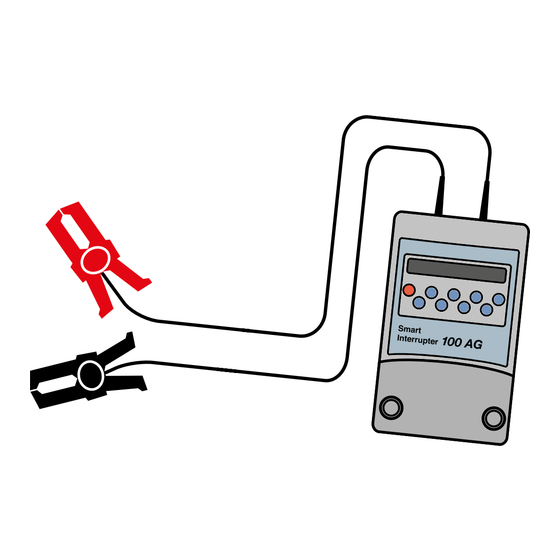
The Smart Interrupter provides a means of placing
a characteristic signature on pipes by interrupting
the flow of cathodic protection (CP) current.
The Smart Interrupter is specifically designed for use with
the Radiodetection Stray Current Mapper (SCM) and
Pipeline Current Mapper (PCM+) but can also be used as a
stand-alone interrupter.
Advertisement
Table of Contents

Subscribe to Our Youtube Channel
Related Manuals for Radiodetection Smart Interrupter 50AG


Summary of Contents for Radiodetection Smart Interrupter 50AG
- Page 1 (CP) current. The Smart Interrupter is specifically designed for use with the Radiodetection Stray Current Mapper (SCM) and Pipeline Current Mapper (PCM+) but can also be used as a stand-alone interrupter.
-
Page 2: User Controls
The Smart Interrupter is a solid state interrupter, designed for use by the trained corrosion technician on cathodic protection systems in outdoor locations. For safe operation of the equipment please ensure you read, understand and follow the instructions in this guide. User Controls Power On/Off Selects Stray Current Mapper (SCM). -
Page 3: External Connections
External connections Output cable entries Serial synchronization GPS antenna connector connector socket socket External Power Connecting the Rectifier Optional external supply Smart Interrupter Always switch off the CP system before connecting and disconnecting the Smart Interrupter. Structure cable Smart Interrupter Before connecting the Smart Interrupter to the CP supply, measure... - Page 4 When disconnecting the external supply lead, always remove it from the Smart Interrupter before disconnecting it from the anode wire. To prevent unauthorized access keep the Smart Interrupter secure if it is left unattended when in use. Operating the Smart Interrupter (non-GPS version ) Note: Operating procedures are the same for both the 50 amp and 100 amp versions.
-
Page 5: Pulse Mode
Pulse Mode In pulse mode the Smart Interrupter puts a simple on/off pulse onto the line and assists in signal identification when using more than one Smart Interrupter at the same time. If using more than one Smart Interrupter make the pulse On/ Off times different for each unit. -
Page 6: Timer Mode
Previous Settings To retrieve any one of the last ten settings in pulse mode, press and hold down the pulse button and at the same time press either the left or right arrow button. The screen will cycle through the last ten settings, showing the number of each setting (1 is the most recent). - Page 7 Master-Slave Synchronization using the synchronization lead Note: This method is not recommended when using the Smart Interrupter with the SCM. When using several Smart Interrupters at the same time they must be time synchronized with each other to ensure signal compatibility.
- Page 8 master synchronized Unit, an ‘m’ is displayed on the screen. If you attempt to change a setting that would make the master/slave patterns incompatible, the Smart Interrupter emits a 2-second tone and the following screen is displayed. Pressing the OK button will allow the settings to be changed but with no further warnings being displayed, and synchronization may be lost.
-
Page 9: Setting The Timer
Antenna Fault (flashing symbol)-replace antenna Position (steady symbol)-move Smart Interrupter to a better GPS reception area Signal level Minimum signal strength / Maximum signal strength Synchronization being determined Synchronization to GPS OK last time No synchronization to GPS last time (“free running”) Timer Mode Note: The Smart Interrupter clock is automatically adjusted every time a GPS signal is received. - Page 10 Note: If the unit is set to Running, the resistance value will fluctuate between these readings as the switch turns On and Off. If either resistance measurement is outside the limits stated above, the unit should be returned to Radiodetection for service. Smart Interrupter Maintenance The Smart Interrupter is powered by 2 x LR20 (D-cell) batteries.
-
Page 11: Specifications
Authorised Service Center for replacement. Cleaning Wipe down with a moist cloth. RS232 connector (for Radiodetection use) Maintenance There are no user serviceable Batteries parts within the equipment. Battery cover Specifications... - Page 12 © 2017 Radiodetection Ltd. All rights reserved. Radiodetection is a subsidiary of SPX Corporation. Radiodetection is a trademark of Radiodetection Ltd. Due to a policy of continued development, we reserve the right to alter or amend any published specification without notice.
Need help?
Do you have a question about the Smart Interrupter 50AG and is the answer not in the manual?
Questions and answers