
Subscribe to Our Youtube Channel
Related Manuals for Radiodetection PCMx


Summary of Contents for Radiodetection PCMx
- Page 1 PCMx ™ Radiodetection’s world leading Pipeline Current Mapping System Operation Manual 90/PCMX-OPMAN-ENG/02...
-
Page 2: Table Of Contents
6.6 ACCA Surveys .......... 23 2.1 About this manual ........4 6.7 ACVG Surveys .......... 24 2.2 Overview of the PCMx system ..... 4 6.8 Comparing Fault Severity ......25 2.3 PCMx system features ......... 4 6.9 Simultaneous ACCA and ACVG Survey ..26 2.4 PCMx transmitters ........ -
Page 3: Preface
This equipment shall be used only by qualified and 1.1 Before you begin trained personnel, and only after fully reading this Operation Manual. Thank you for your interest in Radiodetection’s Pipeline Current Mapping System. WARNING: Direct connection to live conductors is POTENTIALLY LETHAL. Direct connections... -
Page 4: Training
Batteries should be disposed of in accordance with your company’s work practice, and / or the relevant laws or Please contact Radiodetection for a copy of the full text guidelines in your country or municipality. of the EU declaration of conformity. -
Page 5: Introduction
The PCMx locator comes supplied with a PCM magnetometer attachment and while connected the 2.3 PCMx system features locator will operate as a PCMx locator. If the attachment is removed, the locator will operate as a RD8100PDLG Consists of two portable transmitters, a handheld cable and pipe locator. -
Page 6: Pcmx Locator
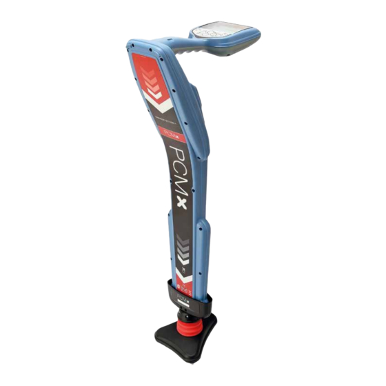
2.5 PCMx Locator PCMx locator is used to locate the pipeline, even in heavily congested areas. The locator provides the operator with a measurement of depth, current and direction of the low frequency signals applied by the system’s transmitter. -
Page 7: Tx-25 And Tx-150 Pcm Transmitter
In certain situations, the air pressure within the case may need to be equalized by unscrewing the small knob located near the handle. 3.1 Transmitter control panels Fig. 3.1: Tx-150 PCM Transmitter © 2021 Radiodetection Ltd... -
Page 8: Transmitter Features
PCMx Operation Manual Fig. 3.2: Tx-25 PCM Transmitter 3.2 Transmitter Features 3.3 Transmitter Controls 1. On/Off switch. Frequency Select 2. LCD display: Indicates current output, (4Hz or 8kHz) in Amps. The 4Hz current is displayed on the transmitter display. 3. LED indicators. Provide critical feedback on the transmitter’s operation. -
Page 9: Output Current Selector
30mA, 60mA, 100mA, 300mA, 600mA, 1A transmitter is left switch on for very long periods. Transmitter status Tx-25 and Tx-150: Over Temperature If the transmitter temperature exceeds its recommended limits it will automatically shut down. The over © 2021 Radiodetection Ltd... -
Page 10: Lcd Display
PCMx Operation Manual temperature LED will extinguish once the unit has cooled It is possible to power the Tx-150 using a supply from a down sufficiently. vehicle DC to AC inverter. This supply will need to be capable of providing at least 650W or more Power Limit ... - Page 11 Note On the TX10, only 512Hz, 640Hz or 8kHz can be used as the locate frequency. If using 512Hz or 640Hz, set the PCMx to LFCD mode or 8kHz mode if using 8kHz. © 2021 Radiodetection Ltd...
-
Page 12: Pcmx Locator
PCMx Operation Manual PCMx locator Note: Before you attempt any survey, set the PCMx locator to match your country’s power distribution 4.2 Locator Keypad frequency (50 or 60Hz) and your preferred units of measurement. See Section 3.3 for instructions. Power key Frequency key to change frequencies 4.1 PCMx Locator Features... -
Page 13: Locator Screen Icons
Fig. 4.2: PCMx locator screen icons 4.3 Locator Screen icons Compass: Shows the orientation of the located cable or sonde relative to the locator. Transmitter communication status - iLOC™ (Tx-1, Tx-5, Tx-10 only) Signal strength bar graph with peak marker. -
Page 14: Locator Information
Bluetooth. locator. However, the battery type must be changed in GPS – Enable, disable or reset the internal GPS the PCMx locator menu if other battery types are to be module. used. UNITS –... - Page 15 Charging the battery pack WARNING! Only use charging equipment provided by Radiodetection. The use of alternative chargers may cause a safety hazard and/or reduce the life of the battery. CAUTION: Do not let your battery completely discharge as this may reduce its life or damage it permanently.
- Page 16 PCMx Operation Manual Fig. 4.5: Li-ion battery pack connection Fig. 4.7 : Repeat then lift the battery pack away Note: Fully charge your lithium-ion battery pack before its To fit a new battery, lift both accessory covers slightly, first use...
-
Page 17: Self-Test
Key to enter. Scroll to the ON option and confirm with the frequency key 4.9 Antenna modes The PCMx locator supports 5 antenna modes to suit your particular application or the local environment. To scroll between antenna modes, press the antenna key. -
Page 18: Depth Measurement
512Hz / 640Hz 4.13 GPS Cathodic Protection Locate Signal 100Hz /120Hz The PCMx is equipped with built in GPS. If GPS co- ordinates are required to be added to survey 8kHz 8kHz Locate Signal 8192Hz measurements the GPS module will need to be enabled. -
Page 19: Uploading Pcmx Datalogs
Note: When a measurement is taken, the log number selected to be overwritten will be displayed on the The PCMx provides the user with the opportunity to send screen. Accepting the measurement will overwrite data from the locator to a PC by uploading the entire log the selected log. -
Page 20: Connecting Transmitter To
PCMx Operation Manual Connecting Transmitter to Pipeline WARNING: Appropriate safety procedures must be followed before removing pipeline CP connection. Only personnel trained and qualified to work on rectifiers should remove CP connections. Note: Always switch off the rectifier before connecting leads. -
Page 21: When A Rectifier Is Not Available
Connect the white PCM transmitter lead to one of the pipeline cables, and the green connection lead to the anode cable. Use the PCMx locator to help identify the cables to the individual pipelines. If the PCM transmitter signal is applied to more than one pipeline at a time, the signal will be divided between them, so the maximum range will be reduced. - Page 22 PCMx Operation Manual Connect the white cable from the PCM transmitter to the pipeline connection, and the green cable from the PCM transmitter to the anode. Note: If the anode is heavily depleted it will be high resistance, and the transmitter signal lights will indicate higher voltage.
-
Page 23: Surveying A Pipeline
Guide arrows should be at minimum pipeline length with both left and right arrow heads lit. To fully align the PCMx with the pipeline, rotate the This section describes how in practice surveys locator until the compass is in the 6 O’clock position. -
Page 24: Trudepth
7.5 degrees services, etc. both depth and current readings will be disabled. The loss of PCMx current will be virtually proportional to the amount of CP current being used at the fault. 6.4 Current Direction (CD) See section 4.14 on how to take a 4Hz current... -
Page 25: Acvg Surveys
A-Frame spikes, and this allows a comparison to be made between different faults to determine the most severe. This numeric value along with the direction arrows can be stored in the PCMx, recalled, and uploaded via the PCM Manager application. Method... -
Page 26: Comparing Fault Severity
25cm (or smaller) intervals. Note the highest dBuV the pipe line, rotate the A-Frame 90° so that the reading, or save it in the PCMx and note log number. green spike points towards the pipeline. Move back During the survey, you can switch to locating the pipeline... -
Page 27: Simultaneous Acca And Acvg Survey
The PCMx will automatically select ACVG mode and an A-frame symbol will be displayed. Press the ‘f’ key until the mode of the PCMx locator matches either ELCD or LFCD as chosen from the transmitter. -
Page 28: Theory And Application
(short or poor coating). Loops If the current arrow changes direction it could indicate the pipe has changed location. Use the PCMx in locate mode to relocate it – see Fig 7.3. Fig. 7.2: Tie line 2... -
Page 29: Pipelines And Pipeline Defects
The following diagram is a typical street involving ‘Tie-ins’ and an ‘L’. The readings from the PCMx and distances to prevent interference have been included. By working around the map a short was quickly and easily detected. -
Page 30: Parallel Pipes
PCMx Operation Manual 7.3 Parallel Pipes Mixture of good and poor coating, which is shown as greater current loss over the section of pipe with poor Consider a new distribution pipe with the old pipe running coating. parallel and about 30cm (12 inches) away with a 1 Amp signal applied. - Page 31 Section C Good Peak and Null locate with a rise in current The short would be at the point where the current drops and then a steady rate of decrease. close to zero. The graph in Figure 7.11 illustrates this effect. © 2021 Radiodetection Ltd...
- Page 32 PCMx Operation Manual Another service was found to be close to the new pipeline in It was found that another service was shorted to the Section B and had a small amount of current flowing in the pipeline as shown and at some stage ran parallel to the opposite direction.
- Page 33 This indicated that the bonding point was further ahead. The point of bonding was located, and a measurement of 500mA, concluded that the other faults existed closer to the rectifier. © 2021 Radiodetection Ltd...
-
Page 34: Interpreting Result
8.1 Introduction vehicles, moving vehicles, boots or shoes with steel toe-caps or large metal structures. The principle of the PCMx is that the frequency used is so Taking readings near to PCMx Transmitter and low (4Hz) that the effects of induced and capacitance coupling to other lines are reduced to almost zero. -
Page 35: Using Dbma For Pipeline Current Mapping
See Fig. Figure 8.1 Graph ‘C’ shows what would be expected in the 8.3. real situation if PCMx currents were plotted over a section of pipe with a coating defect. Depending on the fault characteristics, the effect of the... - Page 36 Note the recovered reading is less than the signal before the trouble. Further investigations using the PCMx A-Frame should now be undertaken so as to pinpoint the exact position of the faults.
-
Page 37: Pcm Manager
PCM Manager is a PC application that can be downloaded from the Radiodetection website and installed onto a PC. Once installed the PCMx locator can be connected to the PC via a USB connection. Stored PCMx survey measurements can be uploaded and used to quickly evaluate the condition and position of coating defects. -
Page 38: Maintenance
PCMx Operation Manual Maintenance 9.1 General Maintenance Service and maintenance The PCMx locator and transmitters are robust, durable The locator and transmitter are designed to minimize the and weatherproof. However, you can extend your requirement for regular calibration. However, as with all equipment’s life by following these care and maintenance... -
Page 39: Warranty
9.4 Warranty that may result from its use. No license is granted by implication or otherwise under any patent rights of PCMx locators are covered by a 1-year warranty as Radiodetection or third parties. standard. Customers can extend the warranty period to a total of 3 years by registering the PCMx within 3 months from purchase. - Page 40 Copyright © 2021 Radiodetection Ltd. All rights reserved. Radiodetection is a subsidiary of SPX Corporation. Radiodetection, PCMx, PCM, and RD8100 are trademarks of Radiodetection in the United States and/or other countries. Due to a policy of continued development, we reserve the right to alter or amend any published specification without notice. This document may not be copied, reproduced, transmitted, modified or used, in whole or in part, without the prior written consent of Radiodetection Ltd.
Need help?
Do you have a question about the PCMx and is the answer not in the manual?
Questions and answers