Table of Contents
Advertisement
Quick Links
Advertisement
Table of Contents

Related Manuals for Radiodetection RD500


Summary of Contents for Radiodetection RD500
- Page 1 RD500 Water pipe locator kit Operation Manual 90/RD500-OPMAN-MET/01...
- Page 2 Please read this user manual in its entirety give inaccurate readings. before attempting to use the RD500 system as it contains many important safety notices and Keep this equipment clean and arrange for warnings.
-
Page 3: Table Of Contents
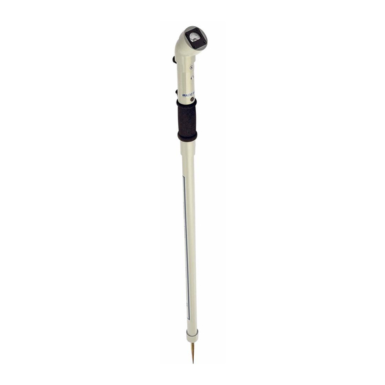
RD500 THEORY Vibration Stage I: Water Flowing Stage II: Pressure Wave Created Stage III: Pressure Wave is Reflected Stage IV: Pulse Transmitter Flow is Re-established Seismic Disturbance RD8100 Response vs. RD500 Response RD500 Operating Parameters Expectations P a g e... - Page 4 Locator Photograph RD500 Theory and use LIST OF TABLES Table 2.1 Pulse Transmitter Type Summary Table 2.2 Pulse Transmitter Failure Symptoms & Causes Table 2.3 RD500-Tx Failure symptoms & Causes Table 3.1 Locator Failure Symptoms & Causes P a g e...
-
Page 5: Introduction
PART I - OPERATING GUIDE Unpacking and Set-up: Your RD500 Locator comes packaged in a special carrying case that has compartments for the Locator with spike installed, a hard surface plate and the headphones. Each kit that you order is pre-assembled and ready for use. -
Page 6: Pulse Transmitter Application Techniques
Additional Notes and Precautions: RD500 readings do not indicate depth and the RD500 does not detect buried electrical power lines, gas lines or other hazardous underground objects, so always dig carefully in the proximity of buried pipes or cables... -
Page 7: Locator Application Techniques
T-handle from moving (walking) while pulsating. Locator Application Techniques: Two devices are provided for probing the surface with the RD500 Locator. A 14cm ground spike is supplied for soft surfaces and a brass hard surface plate is included for hard surfaces such as concrete or tarmac (asphalt). -
Page 8: Locator & Adapter Kit Details
Best location results are obtained by beginning your tracing at least 3 metres from the location where the Pulse Transmitter is connected. The signal levels are normally too strong in the area immediately surrounding the Pulse Transmitter. Alternately, tracing may begin at a known pipe location that is not more than 75 metres down the pipe from the Pulse Transmitter. -
Page 9: Sprinkler/Hose Bib Kit Details
Sprinkler/ Hose Bib Kit Details: Hydrant Standpipe Kit Details: P a g e... -
Page 10: Rd500-Tx Electronic Pulse Transmitter
RD500-Tx Electronic Pulse Transmitter Kit Water Meter Standpipe Kit details 10 | P a g e... -
Page 11: Part Ii - Troubleshooting Guide
PART II - TROUBLESHOOTING GUIDE Introduction: This part of the manual is divided into two major subjects. Section 2 covers the Pulse Transmitter and Section 3 covers the Locator. Each section is organized to first provide an overview of the equipment and its major components. -
Page 12: Pulse Transmitter Simplified Block Diagram
Figure 2.2 Pulse Transmitter Simplified Block Diagram Figure 2.2 is a simplified block diagram of the Pulse Transmitter illustrating the operation of the valve. Valve opening and closing is controlled by the adjustable T-handle. Turning the handle clockwise increases the spring force and causes the valve to open (water starts flowing), while rotating it anticlockwise reduces the spring force allowing it to close (water stops flowing). -
Page 13: Pulse Transmitter Tests
Check the filter washer screen (located inside the inlet of the Pulse Transmitter) for debris. Remove and clean if dirty. Replace filter washer if screen is damaged in any way. Be sure to only use filter washers approved by Radiodetection and to install the screen with the cone pointing outward as shown in Figure 2.3. -
Page 14: Leak Tests
If the inlet has been crushed or bent, the Pulse Transmitter must be returned to Radiodetection for repair. Examine the upper Pulse Transmitter body and make sure no leaks are occurring in the body or around the seal between the upper and lower Pulse Transmitter bodies. - Page 15 Turn the water fully on (open valve completely). Loosen the T-handle collar (knurled ring or hex-shaped collar just above T-handle). Turn the T-handle on the Pulse Transmitter clockwise until water starts flowing through the water hose on the outlet. Slowly turn the T-handle anticlockwise until the Pulse Transmitter starts to pulse. Turn the T-handle clockwise until the pulsing stops and observe its position (rotational location) and then turn the T-handle anticlockwise again until you observe the slowest pulse rate.
-
Page 16: Pulse Transmitter Failure Symptoms
RD500 Locator Repairs Purpose of the RD500 Locator: The RD500 Locator picks up the signal created inside the pipe by the Pulse Transmitter. The Pulse Transmitter creates this signal by automatically opening and then rapidly closing a water valve. This allows water to alternately flow out of a pipe for a short period of time and then be quickly stopped for a short period of time. -
Page 17: Locator Tests
The needle should register the GREEN battery zone. If the battery test fails, turn the RD500 back to off and open the battery compartment by turning the battery button anticlockwise until it pops up. The button is located just above the handle grip on the back side of the pole. -
Page 18: Locator Sensitivity Test
3.2.1.2 Locator Sensitivity Tests: Each RD500 Locator Assembly is calibrated at the factory to produce specific meter signal levels when the complete assembly is tested with a platform that produces controlled levels of motion. The following test can be conducted without special equipment to determine if your Locator has sensitivity problems and should be returned to Radiodetection for repair. -
Page 19: Operational Tests
If the meter does not return below 10% quickly after being tapped, and you hear a tone, then the Locator is breaking into oscillation and may need to be returned to Radiodetection for repair. If a tone (oscillation) is heard, try reducing the sensitivity by turning the knob anticlockwise about 1/ 4 turn. -
Page 20: Locator Cleaning, Inspection & Repair
If it can be pulled out, it must be returned to Radiodetection for repair. If you have problems that require further assistance, please call your local Radiodetection Sales Office or use our Customer Support Portal http://support.radiodetection.com... -
Page 21: Rd500 Theory
RD500 THEORY Vibration: Vibration is applied at a single point and attenuates rapidly as the soil absorbs the movement. 21 | P a g e... -
Page 22: Stage I: Water Flowing
Stage 1: Water Flowing Water Flows Velocity increases as it passes through narrow valve aperture Pressure to close the Pulse Transmitter builds Pressure behind Pulse Transmitter “T” seat reduces Pressure builds to a point at which it closes the Pulse Transmitter ... -
Page 23: Stage Ii: Pressure Wave Created
Stage 2: Pressure Wave Created Pulse Transmitter is closed Flow ceases Pressure continues to build Pressure has nowhere to go and returns in the form of a pressure wave back along the pipe 23 | P a g e... -
Page 24: Stage Iii: Pressure Wave Is Reflected
Stage 3: Pressure Wave Is Reflected The pressure wave meets the reservoir (main) The pressure wave continues at reduced intensity in both directions along the run Some of the pressure wave reflects back towards the Pulse Transmitter 24 | P a g e... -
Page 25: Stage Iv: Pulse Transmitter Flow Is Re-Established
Stage 4: Pulse Transmitter Flow is Re-established As a result of the T-Seat being closed, the flow ceases The pressure wave creates a trough of reduced pressure in its wake Combination of first two steps allows the spring to reopen the Pulse Transmitter ... -
Page 26: Seismic Disturbance
Seismic Disturbance: 26 | P a g e... -
Page 27: Rd8100 Response Vs. Rd500 Response
RD8100 Response vs. RD500 Response RD8100 NULL RD8100 PEAK 27 | P a g e... -
Page 28: Rd500 Operating Parameters
“bog-type” soil, hardpan). • Spike can penetrate beyond the 50mm surface vibration zone. Expectations There are crucial differences between using a “Precision” Radiodetection locator and the RD500. There are also some important similarities. SIGNAL APPLICATION Differences: Messy to apply signal (mud, water f lowing, etc.) - Page 29 This document may not be copied, reproduced, transmitted, modified or used, in whole or in part, without the prior written consent of Radiodetection Ltd. The RD500 is manufactured by Heitman Laboratories, Inc., Plano, Texas, USA and is protected by national patents.
- Page 30 This document may not be copied, reproduced, transmitted, modified or used, in whole or in part, without the prior written consent of Radiodetection Ltd. The RD500 is manufactured by Heitman Laboratories, Inc., Plano, Texas, USA and is protected by national patents.
Need help?
Do you have a question about the RD500 and is the answer not in the manual?
Questions and answers