Table of Contents
Advertisement
Quick Links
T631 TDR
High Specification Coaxial
Cable Fault Locator
Operating Manual
Issue 6
Refer to Preface and Safety Instructions before operating
Radiodetection Ltd.
Western Drive
Bristol
BS14 0AF
United Kingdom
Tel: +44 (0) 117 976 7776
Fax: +44 (0) 117 976 7775
00901209-6
E-mail: sales.uk@radiodetection.spx.com
Advertisement
Table of Contents

Related Manuals for Radiodetection T631 TDR


Summary of Contents for Radiodetection T631 TDR
- Page 1 T631 TDR High Specification Coaxial Cable Fault Locator Operating Manual Issue 6 Refer to Preface and Safety Instructions before operating Radiodetection Ltd. Western Drive Bristol BS14 0AF United Kingdom Tel: +44 (0) 117 976 7776 Fax: +44 (0) 117 976 7775 00901209-6 E-mail: sales.uk@radiodetection.spx.com...
- Page 2 © Radiodetection Ltd 2007. All rights reserved. This document is copyright and may not be copied or reproduced or transmitted or modified or used, in whole or in part, in any way whatsoever, without the specific prior written consent of Radiodetection Ltd. Radiodetection Ltd. 00901209-6...
-
Page 3: Table Of Contents
Radiodetection Ltd. 00901209-6 CONTENTS Page Preface & Safety Introduction Front Panel - Controls & Indicators Power Sources Display Operating Modes Operating Instructions General Switch On Programming from the Help Menu Setting Dielectric (PVF) Connecting to cable under test Locating a cable fault Use of left hand cursor 7.7.1... - Page 4 Storing a trace Recalling a trace Comparing a live and stored trace Difference between a live and stored trace 40 RS232 Printing and PC Interface Help Menu Error Messages Specification Product Safety Data Appendix – Bicotest Product Range Radiodetection Ltd. 00901209-6...
-
Page 5: Preface & Safety
Radiodetection Ltd. 00901209-6 PREFACE & SAFETY HEALTH AND SAFETY AT WORK ACT 1974 SECTION 6.1 (C) This product is tested and supplied in accordance with published specifications and, when used in normal or prescribed applications and within the parameters specified, it will not cause danger or hazard to health or safety. - Page 6 The T631 is provided with a set of 2 Ah rechargeable NiCad cells. These are supplied in the discharged state and must be charged for 24 hours before use. Charge the batteries as described in section 4. Note that full rated capacity may not be achieved for the first three cycles of use. Radiodetection Ltd. 00901209-6...
-
Page 7: Introduction
Radiodetection Ltd. 00901209-6 INTRODUCTION The Model T631 is a pulse reflection (TDR) Cable Test Set, for locating cable faults and evaluating changes in impedance caused by connectors, taps, terminations etc. Pulses transmitted into a cable are reflected by cable imperfections. The transmitted pulse and the reflected pulse(s) are shown on the display. - Page 8 T631 OPERATING MANUAL SAMPLE TRACES Open circuit/high impedance series faults Note: Positive (upward) reflection Transmit Pulse Reflected Pulse Short circuit/low impedance shunt faults Note: Negative (downward) reflection Transmit Pulse Reflected Pulse Radiodetection Ltd. 00901209-6...
- Page 9 Radiodetection Ltd. 00901209-6 The T631 will display: A “live” trace. A stored trace recalled from the memory. A live and stored trace together for comparison. The difference between a live and stored trace. POWER SOURCE The T631 is powered by 8 rechargeable cells in a compartment accessible from the rear of the T631, or from an external DC power source via the DC jack.
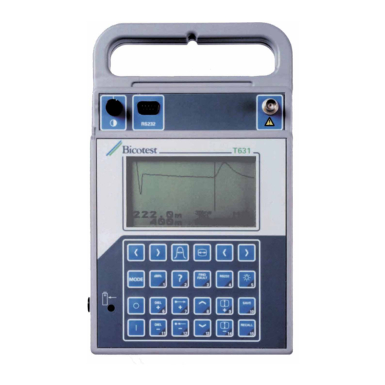
- Page 10 T631 OPERATING MANUAL MAIN FEATURES Figure 1 shows the front panel of T631. Radiodetection Ltd. 00901209-6...
-
Page 11: Front Panel - Controls & Indicators
Radiodetection Ltd. 00901209-6 FRONT PANEL CONTROLS Switches the unit ON. To conserve battery life the unit will switch off 5 mins after the last key operation. If automatically switched off all measurement parameters will be restored when switched on again. - Page 12 Also act as numbers 6 and 11. RANGE Selects the displayed range. The range will increase or decrease and if held down will step through the available ranges. Also act as numbers 7 and 12. Radiodetection Ltd. 00901209-6...
- Page 13 Radiodetection Ltd. 00901209-6 SHIFT Adjusts the vertical position of the live trace. If held down the trace shifts – slowly at first and then quickens. Also act as numbers 8 and 13. AMPLITUDE Adjusts the vertical amplitude of the trace. If held down the unit will step through the available gain stages.
- Page 14 Accesses a “Help” menu for setting machine parameters (see Section 10). Also acts as number 2. RETURN LOSS Enables the return loss between the transmitted pulse and a selected reflected pulse to be determined. Also acts as number 1. Radiodetection Ltd. 00901209-6...
- Page 15 Radiodetection Ltd. 00901209-6 CONNECTORS Input/Output BNC socket to connect to the cable under test. 9 way D connector to interface with a printer or PC. DC jack to supply 12 – 20 V external DC. Note centre is positive. CHARGE INDICATOR Battery Charging Charge Indicator illuminates when the internal battery is being charged.
-
Page 16: Power Sources
Note: When fitting new cells the initial charge period should be 24 hours and 14 hours thereafter. 4.1.2 MAXIMISING BATTERY LIFE Do not recharge until the Battery Low warning is displayed. Do not charge for more than 24 hours. Stay within the RECOMMENDED temperature limits shown in the specification (Section 12). Radiodetection Ltd. 00901209-6... - Page 17 Radiodetection Ltd. 00901209-6 4.1.3 REPLACEMENT Figure 2 shows the rear view of the unit. Cells are accessed by removing the back cover which is secured by 2 fasteners. See specification (Section 12) for cell type. It is recommended that cells are replaced as a set of 8.
- Page 18 The memory back up battery is a lithium manganese cell which is part of the main PCB assembly. The life expectancy is typically four years and replacement is recommended every two years during a routine service to avoid possible loss of stored traces. Radiodetection Ltd. 00901209-6...
-
Page 19: Display
Radiodetection Ltd. 00901209-6 DISPLAY Figure 3 – T631 Display T631 OPERATING MANUAL... -
Page 20: Operating Modes
4. DIFF (L – M) the trace displayed is the difference between the trace of the cable connected to the BNC socket and a selected trace from the memory. Radiodetection Ltd. 00901209-6... -
Page 21: Operating Instructions
Radiodetection Ltd. 00901209-6 OPERATING INSTRUCTIONS GENERAL For correct operation the cable under test should be taken out of service with all sources of supply removed. If this is not possible and the cable is energised or likely to become energised then the blocking filter accessory should be used. -
Page 22: Programming From The Help Menu
Selects UNITS by pressing the key indicated. Select Feet, Metres or Time by pressing the appropriate key. 7.3.2 DIELECTRIC PARAMETERS Press HELP key to obtain the Menu. Select DIELECTRIC by pressing the key indicated. Select PVF, V, or by pressing the appropriate key. Radiodetection Ltd. 00901209-6... -
Page 23: Setting Dielectric (Pvf)
Radiodetection Ltd. 00901209-6 7.3.3 IMPEDANCE Press HELP key to obtain the Menu. Select IMPEDANCE by pressing the key indicated. Select 50, 75 or 93 Ω by pressing the appropriate key. 7.3.4 PULSE SELECTION A fixed pulse width may be selected by pressing HELP, PULSE WIDTH and then choosing the required pulse. - Page 24 JELLY FILLED 0.64 PAPER (0.83 uF) 0.72 PAPER (0.72 uF) 0.88 POWER PILC 25 kV 0.54 XLPE 0.52 0.41 CATV QR PARA III 0.88 PARA I 0.82 T, TR 0.87 TX, TX10 0.89 RG6, RG11, RG59 0.82 Radiodetection Ltd. 00901209-6...
- Page 25 Radiodetection Ltd. 00901209-6 OPTION MAIN TYPE SUB TYPE DIELECTRIC SETTING M/µs TYPE 1 0.78 TYPE 2 0.78 TYPE 3 0.62 TYPE 6 0.78 TYPE 9 0.69 DATA RG58 0.78 RG58U 0.66 THICK ETHERNET 0.78 THIN ETHERNET 0.67 RG11, RG6 0.82 For conversion 1 metre = 3.28 feet.
- Page 26 SHORT LENGTH OF SAME TYPE OF CABLE Measure physical length of the sample. Obtain a reading for the apparent length of the cable using any PVF value. Adjust the PVF value until the distance reading indicated is the same as the measured length. Radiodetection Ltd. 00901209-6...
-
Page 27: Connecting To Cable Under Test
Radiodetection Ltd. 00901209-6 CONNECTING TO CABLE UNDER TEST Connect the cable under test directly to the BNC socket or via the test lead supplied. Unless the LH cursor is moved to coincide with the end of the test lead, the distance read out will include the length of the test lead which must be subtracted from the reading obtained. -
Page 28: Use Of Left Hand Cursor
Eliminate the length of the test lead. Measure between any two features on the trace. When moved the LH cursor becomes the live cursor and changes to a solid line, with the RH cursor becoming a broken line. Radiodetection Ltd. 00901209-6... -
Page 29: Eliminating The Length Of The Test Lead
Radiodetection Ltd. 00901209-6 7.7.1 ELIMINATING THE LENGTH OF THE TEST LEAD Connect the test lead to the unit. Select 3 m or 6 m range. Adjust the controls so that the reflection from the end of the test lead is obtained. -
Page 30: Resetting The Lh Cursor
Pressing the key a second or subsequent time locates the next significant feature along the cable. It is essential that the PVF is set to the value appropriate to the cable type in order that distance measurements are accurate (see Section 7.4). Radiodetection Ltd. 00901209-6... - Page 31 Radiodetection Ltd. 00901209-6 Having obtained the display the parameters may then be altered if required. This feature is intended for use on coaxial cables where the reflection from a fault may be quite small, so the sensitivity used is quite high. On a power cable or twisted pair telephone cable, mismatches due to joints, or change of cable type may give rise to many reflections which the instrument will detect even though they are not faults.
-
Page 32: Return Loss Measurements
The amplitude of the reflection resulting from an impedance change, relative to that of the transmitted pulse is a measure of the impedance mismatch at that point and the ratio is referred to as the reflection coefficient. Radiodetection Ltd. 00901209-6... - Page 33 Radiodetection Ltd. 00901209-6 Reflection coefficient ρ = where Ar = amplitude of reflected pulse At = amplitude of transmitted pulse The amplitude of the reflected pulse cannot normally exceed that of the transmitted pulse and therefore the reflection co-efficient cannot exceed unity. It is usual therefore to express the reflection in percentage terms or millirhos (mρ) where:...
- Page 34 T631 OPERATING MANUAL A conversion chart is given below: Reflection Coefficient/Return Loss Conversion Chart Radiodetection Ltd. 00901209-6...
- Page 35 Radiodetection Ltd. 00901209-6 The foregoing assumes an ideal “lossless" cable. In practice, measurements obtained include the effect of pulse attenuation due to cable loss and requires correction in order to obtain true return loss. i.e. True Return Loss = Measured Return Loss – Pulse Attenuation Since the amplitude of the reflection varies with the pulse width it is essential when determining Return Loss to use the SAME PULSE WIDTH for all measurements.
- Page 36 Note: this option is not displayed on screen but is available. Ensure printer lead is plugged into the instrument and printer and that the printer is ready to print (see section 9). Press key 8 to return to normal operation. Radiodetection Ltd. 00901209-6...
- Page 37 Radiodetection Ltd. 00901209-6 Notes Note that a positive dB value (or mrho value <1000) indicates a return loss (i.e. the reflection is smaller than the transmit pulse). Under certain conditions it is possible for the reflection to have a greater voltage amplitude than the transmit pulse. In this case the dB value will be shown as negative and the mrho figure will be greater than 1000.
-
Page 38: Filter
“Measurement of Pulse Attenuation”. 7.10 FILTER A low pass filter is available from the Help menu. It is used to reduce noise, especially on high gain settings. It should not be used with the 2 ns and 10 ns pulses. Radiodetection Ltd. 00901209-6... -
Page 39: Use Of The Memory
Radiodetection Ltd. 00901209-6 USE OF THE MEMORY STORING A TRACE Obtain the desired LIVE trace using the method previously described in Section 7. Press the SAVE key and then select the desired Memory location by pressing the appropriate key. The live trace is now stored in the selected memory location, together with the associated machine settings. -
Page 40: Difference Between A Live And Stored Trace
If not already connected to the cable under test, connect to the cable and observe the trace which is the difference between the live and recalled trace. To view the LIVE trace and recalled trace separately use the MODE key and then select LIVE (L) OR MEMORY (M) as required. Radiodetection Ltd. 00901209-6... -
Page 41: Rs232 Printing And Pc Interface
Radiodetection Ltd. 00901209-6 HELP MENU When in the MEMORY mode, if the HELP menu is accessed, those keys that affect set parameters are disabled. RS232 – PRINTING AND PC INTERFACE Screen information and Memory contents can be transferred to a printer or PC via the RS232 interface. - Page 42 A PC software kit, X600 TRACEability™ is available. This enables a cable database to be established. Data from all memories can be transmitted to, and received from, a PC. See the manual supplied with the software for full instructions. Radiodetection Ltd. 00901209-6...
-
Page 43: Help Menu
Radiodetection Ltd. 00901209-6 HELP MENU MACHINE SET UP Impedance Dielectric Pulse Width 2 ns 93Ω 10 ns 75Ω 30 ns 50Ω Help Menu Help Menu 100 ns Operation Operation 300 ns 1200 ns Filter Cable Type Auto Filter ON/OFF Telephone... -
Page 44: Error Messages
T631 OPERATING MANUAL ERROR MESSAGES When switched on the T631 performs a self test. If it fails the following message is displayed: INTERNAL MALFUNCTION ERROR XX PLEASE REFER TO MANUAL Please contact your supplier and report the error number. Radiodetection Ltd. 00901209-6... -
Page 45: Specification
Radiodetection Ltd. 00901209-6 SPECIFICATION All specifications in this section assume a PVF of 0.667. 1 metre is equivalent to 3.28 feet or 10 nanoseconds. RANGES AND RESOLUTION: Maximum Horizontal Resolution at Accuracy Typically <0.5% (48 m range and above) Displayed... - Page 46 T631 OPERATING MANUAL VERTICAL DEFLECTION: SENSITIVITY Gain Setting Signal for Full Scale Deflection 16 V 960 mV 480 mV 240 mV 120 mV 60 mV 30 mV 15 mV Radiodetection Ltd. 00901209-6...
- Page 47 Radiodetection Ltd. 00901209-6 AUTO MODE PULSE SELECTION Nominal Range Default Pulse Available Pulses (@PVF = 0.667) (ns) (ns) 2, 10 2, 10 12 m 2, 10, 30 24 m 2, 10, 30 48 m 2, 10, 30, 100 96 m...
- Page 48 Configuration 4800 baud, no parity, 8 bits, 1 stop bit. FUNCTION DIRECTION Received Data (RXD) Input Transmit Data (TXD) Output Ground Data Set Ready (DSR) Input Request To Send (RTS) Output Display 240 x 128 pixel LCD 240 x 100 pixel waveform area Radiodetection Ltd. 00901209-6...
- Page 49 Radiodetection Ltd. 00901209-6 Backlight LED with auto switch off (5 mins) Keyboard Sealed membrane Power Sources Battery - internal rechargeable NiCad provides 8 hours operation (excluding backlight). Cells - 8 x R14 External DC: Operating 12 to 20 V 0.25 A Charging 15 to 20 V 0.25 A...
- Page 50 Output 15 V DC 400 mA Environmental & Safety (Main Unit) Safety BS EN 61010-1 : 1993 and IEC 1010-1 : 1990 and Amendment 1 : 1992 Maximum permissible voltage 30 V RMS on input connector for safe operation Radiodetection Ltd. 00901209-6...
- Page 51 Radiodetection Ltd. 00901209-6 Temperature Operating temperature: Including batteries: 0°C to +50°C Excluding batteries: -5°C to +50°C Storage temperature: Including batteries: -20°C to +50°C Excluding batteries: -20°C to +65°C Recommended temperature Charging: +10°C to +35°C limits to maximise battery life Discharging: -5°C to +45°C...
- Page 52 40g, 6ms, 1000 bumps in each of 3 axes (in soft carry case) Free Fall BS EN 60068-2-32 : 1993 part 2, test Ed (IEC 68-2-32 : 1975) (in soft carry case) Water and dust Protection BS EN 60529 (IEC 529 : 1989) To IP54 Radiodetection Ltd. 00901209-6...
-
Page 53: Product Safety Data
Radiodetection Ltd. 00901209-6 PRODUCT SAFETY DATA The T631 is a Pulse Echo Test Set that provides visual indication of cable faults. The T631 is tested and supplied in accordance with our published specifications, and when used in normal or prescribed applications within the parameters specified for electrical and mechanical performance, will not present any danger or hazard to health or safety, provided normal engineering and safety practices are observed. - Page 54 In the event of any damaged items coming into contact with the skin, the affected area should be washed with clean, cold water. In the event of eye contamination, thoroughly irrigate with recognised eyewash and seek urgent medical assistance. Radiodetection Ltd. 00901209-6...
- Page 55 Radiodetection Ltd. 00901209-6 Physical Damage Some of the components used in the assembly may contain very small quantities of toxic materials. There exists a remote possibility that physically damaged components may present a toxic hazard. As a general precaution avoid unnecessary contact with damaged electronic components and arrange for disposal in accordance with local legislation that may currently be in force.
- Page 56 Not necessary for operating the T631, providing that normal safe working practice is observed. Working Environment No special precautions are needed for operating the T631. Appropriate precautions must be observed for potentially hazardous, working environments such as construction site installations, electricity substations, explosive atmospheres, etc. Radiodetection Ltd. 00901209-6...
-
Page 57: Appendix - Bicotest Product Range
Radiodetection Ltd. 00901209-6 Other products available from Bicotest: VIXXON™ S3000 Intermittent LV Fault Location System The unique system solution to intermittent LV Faults BOXXER™ S4000 Power Cable Fault Location System The system solution to intermittent, flashing and high resistance HV faults AXXIS™... - Page 58 Intermittent, Flashing or High HV Fault BOXXER BOXXER Diagnosis S4000 S4000 BOXXER S4000 Pinpoint Fault Resistance HV Prelocate Faults Fault Pinpoint LV & HV AXXIS Fault AXXIS Fault Diagnosis S5000 S5000 AXXIS S5000 Sheath Prelocate Fault Fault Radiodetection Ltd. 00901209-6...
Need help?
Do you have a question about the T631 TDR and is the answer not in the manual?
Questions and answers