
Related Manuals for Radiodetection 1205CXA


Summary of Contents for Radiodetection 1205CXA
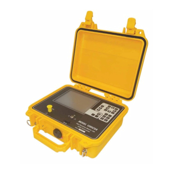
- Page 1 ® Advanced Test Equipment Rentals www.atecorp.com 800-404-ATEC (2832) Model 1205CXA Coaxial Metallic Time Domain Reflectometer Operator’s Manual January 2007...
- Page 2 Thank you for purchasing Riser-Bond Instruments' Model 1205CXA Metallic Time Domain Reflectometer. Our goal is to provide you with a high quality troubleshooting tool which is both powerful and easy to use. We all share a commitment to quality and excellence and will do our best to continue to provide you with test equipment to meet your needs.
-
Page 3: Table Of Contents
TABLE OF CONTENTS SECTION 1: GENERAL INFORMATION....2 SECTION 4: APPLICATION NOTES.......23 TDR Tap Plate Connector......23 Safety Information.........2 Missing Signals, Corroded Splices, and Introduction ..........3 Unidentified Cables........24 General Features..........3 Detecting Intermittent Faults......24 Measuring and Documenting.....25 SECTION 2: OPERATING PROCEDURES....4 Detecting Theft of Service......26 Theory of Operation........4 Front Panel Description .......5 SECTION 5:... -
Page 4: Section 1: General Information
Any Caution sign identifies a Caution temperatures. To insure that your Model 1205CXA will procedure or process, which if not be ready to use, store the instrument indoors during correctly followed, may result in extreme hot or cold temperatures. -
Page 5: Introduction
Automatic and manual cursor placement functions. The Model 1205CXA will test all types of metallic paired Exclusive SUPER-STORE waveform storage. cables for opens, shorts, impedance discontinuities, and many other cabling problems. -
Page 6: Section 2: Operating Procedures
(upward reflection) with the output pulse. If the cable is a short circuit, the reflected The Model 1205CXA displays the cable under test as pulse will be out-of-phase (downward reflection) with a digitized waveform with a numeric distance readout the output pulse. -
Page 7: Front Panel Description
WAVEFORM LIGHT POSITION CONTRAST V GAIN V GAIN CONTRAST RANGE RANGE CURSOR 1 CURSOR 1 CURSOR 2 CURSOR 2 MODEL 1205CXA High Resolution Metallic TDR Cable Fault Locator CABLE CHARGER SERIAL # RS-232... - Page 8 Keypad Cursors The 1st and 2nd cursor keys move the cur- I/O Use the I/O key to turn the instrument on and off. sors along the waveform. Use the 2nd cursor arrows to move the second cursor to the point of interest on Backlight Use the backlight key to turn the CFL back- the waveform.
- Page 9 Additional messages are displayed when utilizing the standard and optional waveform storage functions. E. Menu Pop-up menu for selecting instrument con- B. Pulse Width Model 1205CXA has selectable pulse trols. widths for testing various lengths of cable. F. Selected Menu Items Displays the currently active Displays the level of vertical am- C.
- Page 10 G. Distance Between Cursors The Model 1205CXA automatically calculates and displays the distance between the 1st and 2nd cursors. Each time the cur- sor placement is changed or the VOP is adjusted, the DISTANCE BETWEEN CURSORS reading will auto- matically update.
- Page 11 Pop-up menu Mode Use the two icon keys for cycling through the Store Use the icon keys to select an available storage available display modes for single, dual, or difference location and press the * key to store. waveform display modes. Recall Use the icon keys to select a storage location Overlay Use the two icon keys to adjust the trace sepa- and press the * to recall to display.
-
Page 12: Instrument Operation
2.3 Instrument Operation With the distance format set in feet mode and a 83% VOP, the ranges are 10, 20, 50, 100, 200, 500, 1k, 2k, Proper operation and precise distance readings will be 5k, 10k, 20k feet. insured if you remember the following procedures and choose the mode of operation to best suit your cable Characteristics of RANGE-PLUS operation: testing conditions:... - Page 13 The distance between the cursors is displayed on the LCD. Remember that the distance measurement is not Model 1205CXA's unique dual independent cursors from the transmitted pulse, but from the first cursor to feature allows you to place cursors at, and measure to the second cursor.
- Page 14 2.3.3 Display Modes Live Display Mode Loops: The Display mode loop alternates between Coax and IFD (Intermittent Fault Detection) mode. Displays active test port. Line Displays IFD waveform. Recalled Display Mode Loops: When a waveform has been recalled from memory, the Mode control will cycle through display modes involving the coaxial test port and the recalled waveform.
- Page 15 This is an important difference between the Model can be adjusted, repositioned, zoomed in and out, and 1205CXA and other TDRs. While the waveform is in the cursors moved, without affecting the IFD function. memory, there are three important things to note: The Model 1205CXA will monitor the cable, waiting for an intermittent fault to occur.
- Page 16 Stored IFD waveforms have approximately 2.3.8 Setup Options Menu maximum 1/2 distance range compared to normal Before using your Model 1205CXA, there are several stored waveform of equivalent pulse width. setup options you can choose. The options you choose will remain selected, even when the instrument is turned 2.3.5 Zoom Control...
- Page 17 The instrument will place the first cursor at the end of The Model 1205CXA comes standard with eight SUPER- the test leads. STORE waveform memory locations. The Extended...
- Page 18 1205CXA features NOISE FILTERS. If the Model test. The following table describes minimum distances 1205CXA is connected to a cable with power present, versus pulse width of a stored waveform. the microprocessor automatically filters out the power...
- Page 19 Riser-Bond Instruments has addressed this problem to engage or disengage. by engineering a unique multifunction/multilevel noise filtering system into the Model 1205CXA which can NOTE: It takes longer to generate a waveform greatly improve test results under these types of con- with the noise filter engaged.
- Page 20 POWERED CABLE and FILTER to a fully charged state. The Model 1205CXA may be OFF. operated while the batteries are charging, but this will increase the charging time.
-
Page 21: Section 3: Tdr Fundamentals
VOP for each section of cable to yield the most 3.1 First Time Start-up accurate reading. Before using your Model 1205CXA, there are several 3.4 Cable Impedance setup options you can choose from. Select the Setup menu control and select the desired default settings Any time two metallic conductors are placed close for the instrument. - Page 22 The VOP of a cable can change with temperature, one end and record the fault distance reading. Next, age and humidity. It can also vary from one manu- using the same VOP setting, test from the opposite facturing run to another. Even new cable can vary end of the cable and again record the fault distance as much as +/- 3%.
-
Page 23: Pulse Widths
TDR signal to travel down a into the cable, increase the pulse width. The Model 1205CXA has multiple pulse widths which the operator cable at different levels of energy and distances. The can select to best accommodate the cable length being wider the pulse width, the more energy is transmitted, tested. -
Page 24: Return Loss/ Fault Severity
A unique feature of Model 1205CXA is AUTOMATIC dBRL calculation. This eliminates the need to visually The Model 1205CXA can be set up to display dBRL in and/or manually calculate the RETURN LOSS at a par- two possible modes, Total dBRL and Fault dBRL. -
Page 25: Section 4: Application Notes
Selecting a cable type will also set the VOP of that instead of the original tap plate to gain quick and easy particular cable into the VOP display settings. access to the cable. First, using a two port tap, remove the circuit board. De-solder and remove all the components, from the SECTION 4: APPLICATION NOTES circuit board. -
Page 26: Missing Signals, Corroded Splices, And Unidentified Cables
input tap port and test the cable back to the next tap. Corroded Splices - Within many systems, there are a Double check that there is no AC on the line. Alterna- lot of cable splices. Many are old and their locations tively, connect the lead to the output tap port and read are unknown. -
Page 27: Measuring And Documenting
When using the IFD mode, there should be no power problems arise at a later date. Cables can be periodically present (RF or AC) that can affect the readings. The monitored for signs of deterioration. SUPER-STORE test can take only a few minutes or the instrument can and WAVE-VIEW provide a variety of opportunities and be left on indefinitely to help capture even the most applications not found with any other TDR. -
Page 28: Detecting Theft Of Service
The combination of SUPER-STORE and WAVE-VIEW 2. Test and store the line connected to the house with also make a good tool for TDR training. Students or new the TDR every time you see an illegal tap. For safety employees can use the computer as though it were a reasons, it is usually necessary to test the cable and TDR, which keeps the TDR in the field. - Page 29 no knowledge and was not using the service. Many systems have found that if they can prove that the cable is connected to a device inside the residence, they can prove it is being used. Storing the waveform into the TDR allows the technician to gather evidence for that particular line.
-
Page 30: Section 5: Waveform Examples
SECTION 5: WAVEFORM EXAMPLES A great variety of waveforms may be encountered. This is due to the various applications and electrical and environmental characteristic differences found in the wide variety of cables that exist today. Remember: The reflection of a fault or component will look different on a short length of cable than it will on a long length of cable. - Page 31 P r e s s P r e s s Line 1 Pulse = 2 nsec Line 1 Pulse = 25 nsec V Gain = 4 x V Gain = 1 x = 83% = 83% 1 1 2 ft 8 7 ft L1=08 dBRL...
- Page 32 P r e s s P r e s s Line 1 Pulse = 2 nsec Line 1 Pulse = 25 nsec V Gain = 20 x V Gain = 1 x = 83% = 83% 9 1 ft 1 5 2 ft L1 =22 dBRL...
- Page 33 P r e s s P r e s s Line 1 Pulse = 25 nsec Line 1 Pulse = 2 nsec V Gain = 16 x V Gain = 72 x = 83% = 83% 2 0 3 ft L1 =15 dBRL L1 =55 dBRL...
- Page 34 P r e s s P r e s s Line 1 Pulse = 2 nsec Line 1 Pulse = 2 nsec V Gain = 12 x V Gain = 8 x = 83% = 83% 55 ft 50 ft L1 =36 dBRL...
- Page 35 P r e s s P r e s s Line 1 Pulse = 25 nsec Line 1 Pulse = 25 nsec V Gain = 8 x V Gain = 20 x = 83% = 83% 6 8 6 ft 4 8 4 ft L1=55 dBRL...
- Page 36 P r e s s P r e s s Line 1 Pulse = 25 nsec Line 1 Pulse = 25 nsec V Gain = 128 x V Gain = 32 x = 83% = 83% 4 9 1 ft 5 2 ft L1 =19 dBRL...
- Page 37 P r e s s P r e s s Line 1 Pulse SUB n sec Line 1 Pulse = SUB nsec V Gain 32 x V Gain = 104 x = 83% = 83% 7 2 f t 5 2 ft L1 =40 dBRL L1 =38 dBRL...
-
Page 38: Section 6: Maintenance
SECTION 6: MAINTENANCE Inspect cable accessories for damaged insulation, bent or broken clips. Replace as necessary. Cleaning Remove dust from the outside of the instrument and Warning: To avoid risk of electric shock, do not per- connectors with a lint free cloth or a small, soft brush. form service of any type to the instrument or any ac- cessory. -
Page 39: Section 7: Specifications
SECTION 7: SPECIFICATIONS Display: 320 x 240 dot-matrix liquid crystal display with Specifications for Model 1205CXA cathode fluorescent (CFL) backlighting. Physical - Instrument Only Height: 9.75 inches (25 cm) Power: Battery: Internal, rechargeable, 7.2V Nickel Metal Width: 10.5 inches (27 cm) - Page 40 Software Noise Filters: Standard: 8x Averaging, 50/60 Hz, and Auto- Filter Optional: 4x, 16x, 32x, 64x, 128x Averaging Input Protection: 400V (AC+DC) from DC to 400 Hz, decreasing to at 1MHz. Velocity of Propagation: Two user-selectable display formats VOP (%) with 3 digit precision ranging from 30.0% to 99.9% V/2 with 4 digit precision (feet or meters per microsecond) ranging from 45.0 to 148.0 in meters...
-
Page 41: Appendix A - Serial I/O Printer Port
APPENDIX A APPENDIX B Serial I/O Printer Port Connection VOP Table Epson LQ-860 Emulation CATV Model 1205CXA can interface to an Epson LQ-860 type printer through the Epson LQ-860 command set. CABLE CABLE Serial communication parameters: no parity, two-stop Belden Scientific Atlanta bits, and 9,600 baud. - Page 42 INDEX Impedance 19 Accessories 37 Service 35 Instrument disposal 35 Application notes 22 Set-up options 14 Start-up 18 Storage 15 Keypad 6 Backlight 6 Specifications 36 Battery charger 17 Battery Level Indicator 8 Liquid crystal display 7 Velocity of propagation Cable check 18 Vertical gain 14 Maintenance 35...
-
Page 43: Warranty
WARRANTY Riser-Bond Instruments warranties the Model 1205CXA for a period of ONE YEAR from the date of shipment from Riser- Bond Instruments’ factory or its designated distributor, that the Time Domain Reflectometer Model 1205CXA shall be free from defects in material and workmanship that develop under normal use in accordance with Riser-Bond Instruments operating instructions. - Page 44 Radiodetection Radiodetection Ltd. 154 Portland Road Western Drive Bridgton Bristol ME 04009 BS14 0AF United Kingdom Tel: (207) 647-9495 Toll Free: (877) 247-3797 Tel: +44 (0) 117 976 7776 Fax: (207) 647-9496 Fax: +44 (0) 117 976 7775 E-mail: bridgton@radiodetection.spx.com...
Need help?
Do you have a question about the 1205CXA and is the answer not in the manual?
Questions and answers