Sign In
Upload
Download
Table of Contents
Contents
Add to my manuals
Delete from my manuals
Share
URL of this page:
HTML Link:
Bookmark this page
Add
Manual will be automatically added to "My Manuals"
Print this page
×
Bookmark added
×
Added to my manuals
Manuals
Brands
Austroflamm Manuals
Indoor Fireplace
63x40x42 K 2.0
Operating manual
Austroflamm 63x40x42 Operating Manual
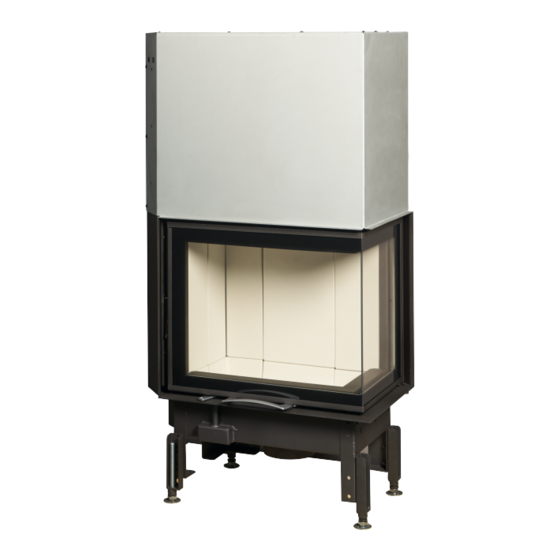
Sliding corner fireplace inserts
Hide thumbs
Also See for 63x40x42
:
User instructions
(56 pages)
,
Operating manual
(86 pages)
1
2
Table Of Contents
3
4
5
6
7
8
9
10
11
12
13
14
15
16
17
18
19
20
21
22
23
24
25
26
27
28
29
30
31
32
33
34
35
36
37
38
39
40
41
42
43
44
45
46
47
48
49
50
51
52
53
54
55
56
57
58
59
60
61
62
63
64
65
66
67
68
69
70
71
72
73
74
75
76
77
78
79
80
81
82
83
84
85
86
87
88
89
90
91
92
93
94
95
96
97
98
99
100
page
of
100
Go
/
100
Contents
Table of Contents
Bookmarks
Table of Contents
Table of Contents
General Information
Copyright
Regulations to be Observed
Purpose of the Operating Manual
Storing the Operating Manual
Structure of the Operating Manual
Representations Used
Version Control
Abbreviations
Safety
Importance of the Safety Instructions
General Safety Instructions
Safety Distance
Special Types of Danger and Personal Protective Equipment
Product Overview
Intended Use
Identifying the Tools
Design Overview
Positioning of the Nameplates
Technical Data
Technical Data under Directive (EU) 2015/1185 and Del. as Per Regulation (EN) 2015/1186
63X40X42-S-2.0
63X40X51-S-2.0
69X49X57-S-2.0
89X49X45-S
89X49X57-S
General Specifications
Data for the Chimney/Flue Dimensioning
Transport and Storage
Transportation
Transport Security
Storage
Requirements at the Installation Location
Requirements at the Room of Installation
Installing the Fireplace Insert
Combustion Air Supply
Combustion Air Duct
Chimney Requirements
Multiple Occupancy
Flue Pipe Connecting Pieces
Fuel Material/-Quantity
Fuel Material
Fuel Quantity
Installation Instructions
Set-Up in Front of or Next to a Wall to be Protected
Convection Air Cladding
Convection Space
Convection Conduction
Fireplace System Without Air Grille (Hypocaust)
Protecting the Installation Base
Expansion Joints
Cladding
Fireplace Aprons
Ornamental Beam
Ceiling above the Fireplace Insert
Floor in Front of the Fireplace Insert
Fire Protection
Heat Insulation Layers and Materials
Electric Cable Runs
Balanced Flue-Tested Fireplace Inserts
Connection to Ceramic Flues
Stove with Ceramic Flue
Connection to Heat Recovery Surfaces
Installation
Risks and Dangers
Durchführung
Placing the Fireplace Insert
Installing the Deflector Plates
Installing the Firebox Lining (Keramott)
Removing the Door
Converting Door to Type BA2
Converting the Flue Pipe
Installing the HMS
Mounting Small Top Storage Box
Assembling Insertcontrol
Mounting the Convection Cladding
Mounting the Design Frame
Solidly Mounting the Design Frame
Support Frame
Settings
Adjusting the Tuning Weight
Commissioning
Initial Commissioning
Operation
Controls
Before Heating up
Fuel
Firing
Heating
Putting on Wood
Heating in the Transition Period
Heating with the Ceramic Flue (Heat Recovery Surface)
Operation
Cleaning
Cleaning Fireplace Insert, Fuel Gas Flues
Removing Ashes
Cleaning the Washers on the Door
Help
Firebox Lining
What to Do in the Event of a Chimney Fire
What to Do in the Event of Faults
What if
Spare Parts
Dismantling
Disposal
Warranty and Guarantee
Start up Log
Service Report
Advertisement
Quick Links
Download this manual
Operating manual
Sliding corner fireplace in-
serts
63x40x42 / 63x40x51
69x49x57
89x49x45 / 89x49x57
www.austroflamm.com
Table of
Contents
Previous
Page
Next
Page
1
2
3
4
5
Advertisement
Table of Contents
Need help?
Do you have a question about the 63x40x42 and is the answer not in the manual?
Ask a question
Questions and answers
Related Manuals for Austroflamm 63x40x42
Indoor Fireplace Austroflamm 63x40x42 K 2.0 Operating Manual
Folding corner fireplace inserts (86 pages)
Indoor Fireplace Austroflamm 45x51/57/68 2.0 K User Instructions
(56 pages)
Indoor Fireplace Austroflamm 65x User Instructions
(72 pages)
Indoor Fireplace Austroflamm 45x Operating Manual
Fireplace insert hatch, flat + ii (112 pages)
Indoor Fireplace Austroflamm 65x Operating Manual
Fireplac inserts slied flat + ii (112 pages)
Indoor Fireplace Austroflamm VUUR DRIE 60 Operating Manual
(94 pages)
Indoor Fireplace Austroflamm 65x51 S 2.0 Operating Manual
(114 pages)
Indoor Fireplace Austroflamm 69x49x57S Operating Manual
Sliding corner fireplace inserts (100 pages)
Indoor Fireplace Austroflamm aquaHEAT 65x51 Operating Manual
(76 pages)
Indoor Fireplace Austroflamm 65x45 K 2.0 Assembly Instructions Manual
Mounting the design frame (20 pages)
Indoor Fireplace Austroflamm Integra II Manual
Insert (31 pages)
Indoor Fireplace Austroflamm Jay User Instructions
(19 pages)
Indoor Fireplace Austroflamm Ruby User Instructions
(132 pages)
Indoor Fireplace Austroflamm 80x64S Manual
(25 pages)
Indoor Fireplace Austroflamm Pallas Operating Manual
(58 pages)
Indoor Fireplace Austroflamm Pallas Back Operating Manual
(58 pages)
This manual is also suitable for:
63x40x51
69x49x57
89x49x45
89x49x57
63x40x42s 63x40x51s
69x49x57s
...
Show all
89x49x45s
89x49x57s
63x40x42s
63x40x51s
63x40x42 s 2.0 left
63x40x42 s 2.0 right
63x40x51 s 2.0 left
63x40x51 s 2.0 right
69x49x57 s 2.0 left
69x49x57 s 2.0 right
89x49x45 left
89x49x45 right
89x49x57 left
89x49x57 right
Table of Contents
Print
Rename the bookmark
Delete bookmark?
Delete from my manuals?
Login
Sign In
OR
Sign in with Facebook
Sign in with Google
Upload manual
Upload from disk
Upload from URL


Need help?
Do you have a question about the 63x40x42 and is the answer not in the manual?
Questions and answers