
Related Manuals for Austroflamm VUUR DRIE 60


Summary of Contents for Austroflamm VUUR DRIE 60
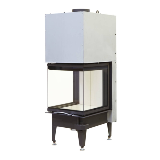
- Page 1 48x51x51 S3 / 48x72x51 S3 64x33x51 S3 / 75x35x45 S3 VUUR DRIE 60/80 Operating manual Fireplace inserts S3 www.austroflamm.com...
- Page 2 Tel: +43 (0) 7249 / 46 443 www.austroflamm.com info@austroflamm.com Edited by: Olivera Stojanovic Illustrations: Konstruktion Text: Technical department (Austroflamm) Copyright All Rights reserved. The contents of these instructions may be reproduced or distributed only with the consent of the publisher! Printing, spelling and typographical errors reserved.
-
Page 3: Table Of Contents
Operating manual Fireplace inserts S3 Contents Contents General information ............................Copyright.............................. Regulations to be observed ....................... Purpose of the operating manual........................Storing the operating manual ......................Structure of the operating manual ....................Representations used.......................... Version control............................. Abbreviations ............................Safety ..................................10 Importance of the safety instructions .................... - Page 4 Contents Operating manual Fireplace inserts S3 Fuel material............................34 Fuel quantity............................36 Installation instructions ............................37 Set-up in front of or next to a wall to be protected ................. 37 Convection air cladding........................39 Convection space ..........................39 Convection conduction........................40 Fireplace system without air grille (hypocaust)................
- Page 5 18 Dismantling................................81 18.1 Removing the door..........................81 18.1.1 48x S3 / 64x33x51 S3 / 75x35x45 S3 / VUUR DRIE 60 80 .............. 81 19 Disposal................................85 20 Guarantee / warranty ............................87 21 Data processing ..............................88 22 Start up log ................................89...
-
Page 6: General Information
Operating manual Fireplace inserts S3 General information You have decided in favour of an Austroflamm fireplace insert. Congratulations on your decision and thank you for your trust. Correct operation and care are essential for trouble-free operation and long service life. Likewise, please follow the instructions in the operating manual. -
Page 7: Regulations To Be Observed
Operating manual Fireplace inserts S3 1 | General information Regulations to be observed • EN 13229 • DIN 18896 • DIN EN 13384 Part 1 and Part 2 • DIN 18160-1 Exhaust systems - Part 1 • EN 12831 • State building regulations of the individual federal states or countries. •... -
Page 8: Purpose Of The Operating Manual
Storing the operating manual Store this manual in case you need it. The current version of the manual can be found on-line at our homepage www.austroflamm.com. Structure of the operating manual The table of contents can be found on page 3. -
Page 9: Abbreviations
Operating manual Fireplace inserts S3 2 | Purpose of the operating manual Abbreviations Abbreviation Meaning Heat Memory System Fireplace insert Ceramic flue Convection cladding... -
Page 10: Safety
3 | Safety Operating manual Fireplace inserts S3 Safety In this manual we give you numerous safety instructions for the safe operation of your fireplace insert. These instructions are characterized differently as follows, depending on their importance: Importance of the safety instructions NOTICE Particular behaviour and/or activities that are required for safe working. -
Page 11: Safety Distance
Operating manual Fireplace inserts S3 3 | Safety Safety distance No flammable objects may be placed within the radiation area of the fireplace insert up to a certain distance (see Technical Data [} auf Seite 14]) measured from the front edge of the firebox opening (a minimum clearance in the Technical Data). -
Page 12: Product Overview
Operating manual Fireplace inserts S3 Product overview Intended use The Austroflamm fireplace inserts described in this manual are manufactured and tested with a type A1 self-closing and locking door under EN test EN 13229. NOTICE Operation is only permissible with the door closed. -
Page 13: Positioning Of The Nameplates
Depth [mm] Height [mm] 1202-1332 Weight [kg] Nominal heat efficiency [kW] Flue pipe outlet, diameter [mm] Ø 150 VUUR DRIE 60 / VUUR DRIE 80 Width (body installation dimension) [mm] Door frame, height [mm] Pane curvature 3-sided 3-sided Width [mm] Depth [mm]... -
Page 14: Technical Data
Technical data Technical data under Directive (EU) 2015/1185 and del. as per Regulation (EN) 2015/1186 5.1.1 48x51x51-S3-2.0 Contact details for the manufacturer or their authorized representative Manufacturer: Austroflamm GmbH Contact: Address: Austroflamm-Platz 1 4631 Krenglbach Austria Appliance details Model identification(s): 48x51x51-S3-2.0... - Page 15 Operating manual Fireplace inserts S3 5 | Technical data Lignite briquettes Peat briquettes Briquettes made from a mixture of fossil fuels Other fossil fuels Briquettes made from a mixture of biomass and fossil fuels Other mixture of biomass and solid fuels (*) PM = dust, OGC = organic gaseous connections, CO = carbon monoxide, NOx = nitrogen oxide (**) Only required when using correction factors F(2) or F(3).
-
Page 16: 48X72X51-S3-2.0
2 and 3.) Specifications are made here for the preferred fuel only. 5.1.2 48x72x51-S3-2.0 Contact details for the manufacturer or their authorized representative Manufacturer: Austroflamm GmbH Contact: Address: Austroflamm-Platz 1 4631 Krenglbach Austria Appliance details Model identification(s): 48x72x51-S3-2.0... - Page 17 Operating manual Fireplace inserts S3 5 | Technical data Peat briquettes Briquettes made from a mixture of fossil fuels Other fossil fuels Briquettes made from a mixture of biomass and fossil fuels Other mixture of biomass and solid fuels (*) PM = dust, OGC = organic gaseous connections, CO = carbon monoxide, NOx = nitrogen oxide (**) Only required when using correction factors F(2) or F(3).
-
Page 18: 64X33X51-S3-2.0
2 and 3.) Specifications are made here for the preferred fuel only. 5.1.3 64x33x51-S3-2.0 Contact details for the manufacturer or their authorized representative Manufacturer: Austroflamm GmbH Contact: Address: Austroflamm-Platz 1 4631 Krenglbach Austria Appliance details Model identification(s): 64x33x51-S3-2.0... - Page 19 Operating manual Fireplace inserts S3 5 | Technical data Peat briquettes Briquettes made from a mixture of fossil fuels Other fossil fuels Briquettes made from a mixture of biomass and fossil fuels Other mixture of biomass and solid fuels (*) PM = dust, OGC = organic gaseous connections, CO = carbon monoxide, NOx = nitrogen oxide (**) Only required when using correction factors F(2) or F(3).
-
Page 20: 75X35X45-S3
2 and 3.) Specifications are made here for the preferred fuel only. 5.1.4 75x35x45-S3 Contact details for the manufacturer or their authorized representative Manufacturer: Austroflamm GmbH Contact: Address: Austroflamm-Platz 1 4631 Krenglbach Austria Appliance details... - Page 21 Operating manual Fireplace inserts S3 5 | Technical data Peat briquettes Briquettes made from a mixture of fossil fuels Other fossil fuels Briquettes made from a mixture of biomass and fossil fuels Other mixture of biomass and solid fuels (*) PM = dust, OGC = organic gaseous connections, CO = carbon monoxide, NOx = nitrogen oxide (**) Only required when using correction factors F(2) or F(3).
-
Page 22: Vuur-Drie-60
2 and 3.) Specifications are made here for the preferred fuel only. 5.1.5 VUUR-DRIE-60 Contact details for the manufacturer or their authorized representative Manufacturer: Austroflamm GmbH Contact: Address: Austroflamm-Platz 1 4631 Krenglbach Austria Appliance details... - Page 23 Operating manual Fireplace inserts S3 5 | Technical data Peat briquettes Briquettes made from a mixture of fossil fuels Other fossil fuels Briquettes made from a mixture of biomass and fossil fuels Other mixture of biomass and solid fuels (*) PM = dust, OGC = organic gaseous connections, CO = carbon monoxide, NOx = nitrogen oxide (**) Only required when using correction factors F(2) or F(3).
-
Page 24: Vuur-Drie-80
2 and 3.) Specifications are made here for the preferred fuel only. 5.1.6 VUUR-DRIE-80 Contact details for the manufacturer or their authorized representative Manufacturer: Austroflamm GmbH Contact: Address: Austroflamm-Platz 1 4631 Krenglbach Austria Appliance details... - Page 25 Operating manual Fireplace inserts S3 5 | Technical data Peat briquettes Briquettes made from a mixture of fossil fuels Other fossil fuels Briquettes made from a mixture of biomass and fossil fuels Other mixture of biomass and solid fuels (*) PM = dust, OGC = organic gaseous connections, CO = carbon monoxide, NOx = nitrogen oxide (**) Only required when using correction factors F(2) or F(3).
-
Page 26: General Specifications
5 | Technical data Operating manual Fireplace inserts S3 Specification mg/m³ for heated filter method (in compliance with Annexe III, number 4, letter a, sec- tion i, point 1) or g/kg for measurement in dilution tunnel (in compliance with Annexe III, number 4, let- ter a, section i, point 2 and 3.) Specifications are made here for the preferred fuel only. - Page 27 Hypocaust heating**) Suitable subject to technical rules *) under examination **) The Austroflamm appliances marked with “suitable subject to technical rules” are suitable for oper- ation in closed systems (hypocausts) ***) at the device connection at nominal heat efficiency The design of the hypocaust must ensure the transport of heat and the even distribution of heat within the cladding so that no part of the heating chamber can be overheated.
-
Page 28: Data For The Chimney/Flue Dimensioning
Pipe Ø 125 mm Pipe Ø 150 mm 75x35x45 S3 Ø 150 mm 120cm² 175cm² 150 / 150 mm Pipe Ø 125 mm Pipe Ø 150 mm Vuur Drie 60 Ø 180 mm 175cm² 255cm² Vuur Drie 80 180 / 180 mm Pipe Ø 150 mm Pipe Ø 180 mm The following points are to be observed for exterior air conduits: • do not create a bend, as the cross-section will be reduced •... -
Page 29: Transport, Handling And Storage
Operating manual Fireplace inserts S3 6 | Transport, handling and storage Transport, handling and storage Transportation Immediately checked the goods delivered for complete- ness and damage in transit. Before installing the fireplace insert, check that all movable parts are working. Any defects before the installation of the fireplace insert must be reported. -
Page 30: Carrying Aids
6 | Transport, handling and storage Operating manual Fireplace inserts S3 In addition with S3 fireplace inserts there are more transport locks at the rear. These must also be removed before in- stallation. For 48x51x51 S3, 48x72x51 S3 models, both transport locks (1+2) should be removed. -
Page 31: Requirements At The Installation Location
Observe the guidelines on fire safety, such as thermal insulation and air grille sizes. DANGER Fire hazard Operating your Austroflamm fireplace insert with too high a fuel feed will create a risk of the chimney and adjacent components or furniture overheating. Combustion air supply For heat-producing appliances that draw their combustion air from the installation room an adequate supply of combustion air into the room must be provided. -
Page 32: Combustion Air Duct
(see state building regulations). Chimney requirements Before set-up or installation of the Austroflamm fireplace insert, the chimney must be checked for its size and quality under the existing local regulations (respectively state building regulations, heating regulations and DIN 18160, Part 1). The mathematical proof of the adequate function of the chimney must be provided in accordance with EN 13384. -
Page 33: Multiple Occupancy
Multiple occupancy All Austroflamm fireplace inserts in this manual have been checked and approved under DIN EN 13229 with self-closing and locking door (designated BA1). Appliances intended to operate BA1 can be connected to a multiple-occupied chimney (if multiple occupancy is possible). The calculation is made according to DIN EN 13384 Part 2. -
Page 34: Fuel Material/-Quantity
8 | Fuel material/-quantity Operating manual Fireplace inserts S3 Fuel material/-quantity Fuel material Wood Many of our native types of wood can, after being appropriately dried, be burnt CO2-neutral in heat- producing appliances. Wood stands out because it grows again, can be sustainably harvested, re- quires little or no extra external energy to be invested in the fuel, and has a short journey from the pro- ducer to the consumer, which provides an optimal climate balance. - Page 35 Operating manual Fireplace inserts S3 8 | Fuel material/-quantity Please observe at all times the maximum specified amount to be laid, even when putting on more wood! Otherwise your fire will not provide the desired efficiency - but above all considerable damage may be caused to your appliance, to gaskets and material and to the flue gas duct.
-
Page 36: Fuel Quantity
8 | Fuel material/-quantity Operating manual Fireplace inserts S3 Approved fuel Dry, properly stored, unrefined log (preferably hard wood) is permitted as fuel for our hybrid stoves Round wood must be split at least once so that it lights better. The diameter of the split piece of wood must not exceed 7 cm. -
Page 37: Installation Instructions
Operating manual Fireplace inserts S3 9 | Installation instructions Installation instructions NOTICE Damage to the appliance The fireplace insert must not have any connection to the housing (minimum gap width 3 mm), as oth- erwise damage may be caused to the appliance. Set-up in front of or next to a wall to be protected 9 10 Fig. 8: Set-up in front of/next to a wall to be protected... - Page 38 9 | Installation instructions Operating manual Fireplace inserts S3 Fig. 9: Set-up in front of/next to a wall to be protected Wall / building wall Thermal insulation layer (flue pipe) Connector Thermal insulation layer (rear panel) Convection room Exterior air intake Concrete slab at least 6 cm (only when being set Ceiling up on a ceiling to be protected)
-
Page 39: Convection Air Cladding
Convection air cladding VUUR DRIE 60 VUUR DRIE 80 Fig. 10: KV cladding Vuur Drie 60 / 80 Convection space • If the convection cladding (appliance part) is not used, a convection space of at least 6 cm depth between fire- place insert (4) and insulation layer (16) to the rear and on both sides must be allowed for. -
Page 40: Convection Conduction
9 | Installation instructions Operating manual Fireplace inserts S3 Convection conduction • The cross-section for the air outlet (14) and the air inlet 50 cm (13) must each be at least 700 cm². • Above at least 200 cm², air inlet and air outlet must not be lockable. -
Page 41: Cladding
Operating manual Fireplace inserts S3 9 | Installation instructions Cladding The room-facing cladding (11) must be made of construction material class A1 non-flammable materi- als. These are e.g. wall tiles, wall bricks, stove tiles, metal, plaster on lathing. Fireplace aprons The fireplace apron must not have any direct connection to the fireplace insert. -
Page 42: Fire Protection
9 | Installation instructions Operating manual Fireplace inserts S3 9.13 Fire protection Fire protection within the radiation area Forwards, upwards and to the sides of the firebox opening, the minimum clearance (seeTechnical Data) to components made of flammable construction materials or flammable components as well as furniture must be complied with. - Page 43 Operating manual Fireplace inserts S3 9 | Installation instructions Insulation materials Delivery Insulation capacity Upper maximum applic- Bulk density ation temperature Group Type Group Type Group Type Group In °C Group kg/m³ Mineral fibre Channels Mats, -200 size 1 Glass fibre Fibres, Mats, -250...
-
Page 44: Electric Cable Runs
9 | Installation instructions Operating manual Fireplace inserts S3 9.15 Electric cable runs There must be no electric cable runs in walls and ceilings within the installation area of the fireplace in- sert. 9.16 Balanced flue-tested fireplace inserts Flue pipe connection •... -
Page 45: Connection To Ceramic Flues
64x33x51 S3 11.86 75x35x45 S3 11.49 VUUR DRIE 80 14.8 VUUR DRIE 60 11.4 Maximum length of chamotte ceramic flues The flue gas temperatures at the appliance collar are average temperatures over the duration of the combustion. Appliance type Flue length [m]... -
Page 46: Stove With Ceramic Flue
10 | Connection to ceramic flues Operating manual Fireplace inserts S3 10.1 Stove with ceramic flue Example using KMS system Example with CVC flue module bricks Thermal insulation Extension wall Floor 125 (combustion air collar) individual individual Fig. 18: Connection to ceramic flue heat exchanger... -
Page 47: Connection To Heat Recovery Surfaces
Operating manual Fireplace inserts S3 10 | Connection to ceramic flues 10.2 Connection to heat recovery surfaces The specifications given in advance in respect of mounting instructions and installation regulations re- main valid (see distances, thermal insulation, exhaust pipe connection). The metallic heat exchanger can be placed to the left or right side or behind the fireplace insert. -
Page 48: Installation
11 | Installation Operating manual Fireplace inserts S3 Installation Installation must only be carried out by an authorized specialist company. Before installing the fireplace insert, check that all movable parts are working. Any defects before the installation of the fireplace insert must be reported. 11.1 Risks and dangers Schutzausrüstung The following protective equipment must be used:... -
Page 49: Installing The Firebox Lining (Keramott)
Operating manual Fireplace inserts S3 11 | Installation 11.2.2 Installing the firebox lining (Keramott) 48x51x51 S3 Numbering = installation sequence 1) Keramott floor 1 - 7 2) Keramott wall 8 - 9 3) Keramott elbow 10 - 15 48x72x51 S3 Numbering = installation sequence 1) Keramott floor area 1 - 7 2) Keramott wall 8 - 9... - Page 50 11 | Installation Operating manual Fireplace inserts S3 64x33x51 S3 Numbering = installation sequence 1) Keramott floor 1 - 7 2) Keramott wall 8 - 10 3) Keramott elbow 11 - 17 75x35x45 S3 Numbering = installation sequence 1) Keramott floor 1 - 7 2) Keramott wall 8 - 10 3) Keramott elbow 11 - 17...
- Page 51 Operating manual Fireplace inserts S3 11 | Installation VUUR DRIE 60/80 numbering = installation sequence 1) Keramott floor 1 - 3 2) Keramott wall 4 - 6 3) Keramott elbow 7- 9...
-
Page 52: Install The Deflector Plates
11 | Installation Operating manual Fireplace inserts S3 11.2.3 Install the deflector plates 48x51x51 S3 1) Hook the upper baffle plate (1) into the two support brackets. 2) Hook the middle baffle plate (2) into the two support brackets. 3) Hook the lower baffle plate (3) into the two support brackets. - Page 53 Operating manual Fireplace inserts S3 11 | Installation 75x35x45 S3 Numbering = installation sequence Fig. 24: 75x35x45 S3 Vuur Drie 60 / 80 Numbering = installation sequence Fig. 25: Vuur Drie 60 / 80...
-
Page 54: Converting Door To Construction Type Ba2
Conversion from construction type BA1 (self-closing door) to construction type BA2 (non-self-closing door). 11.2.4.1 48x51x51 S3 / 48x72x51 S3 / 64x33x51 S3 / 75x35x51 S3 / VUUR DRIE 60+80 1) Move the plate forward on the left and right. Fig. 26: BA1 to BA2... -
Page 55: Rearranging The Flue Pipe Connection
Operating manual Fireplace inserts S3 11 | Installation 11.2.5 Rearranging the flue pipe connection 1) Remove flue pipe bracket (1). 2) Remove cover (2) at the back. 3) Replace and install parts (1+2). Fig. 27: Rearranging the flue pipe connec- tion 11.2.6 Mounting the adapter plate If the adapter plate is mounted, this allows the use of a larger flue pipe connection of 250 mm. -
Page 56: Mounting Small Storage Box
11 | Installation Operating manual Fireplace inserts S3 2) Mount the adapter plate. Fig. 29: Mounting the adapter plate 11.2.7 Mounting small storage box 1) Remove flue pipe bracket. Fig. 30: Removing the flue pipe bracket 2) Place the storage box on to the bolts of the basic ap- pliance and bolt the storage box. -
Page 57: Mounting The Designer Frame
Operating manual Fireplace inserts S3 11 | Installation 3) Mount flue pipe bracket on to the storage box. Fig. 32: Mounting the flue pipe bracket 11.2.8 Mounting the designer frame NOTICE Design frames must not be plastered over nor walled in. 11.2.8.1 S3 designer frame 1) Open the door. - Page 58 11 | Installation Operating manual Fireplace inserts S3 3) Assemble the top part of the designer frame. Fig. 35: Assembling the designer frame 4) Mount designer frame (1) at the bottom. Only loosely fasten the screws and nuts. Fig. 36: Mounting the designer frame at the bottom 5) Position designer frame on the left (1) and right (2) and mount it at the bottom with M5x16 hexagon...
- Page 59 Operating manual Fireplace inserts S3 11 | Installation 6) Mount designer frame (1) at the top with M5x16 hexagon socket screw. Fig. 38: Mounting the designer frame at the 7) The designer frame can be mounted on an optional underframe (2). Fig. 39: Mounting the designer frame on the underframe 8) Evenly align frame and tighten all the screws.
-
Page 60: Mounting The Convection Cladding
11 | Installation Operating manual Fireplace inserts S3 NOTICE The frame can only be loaded if the weight that is resting on the frame is supported via the tensioning parts and the lower part of the solid designer frame. Fig. 41: Aligning S3 DF 11.2.9 Mounting the convection cladding Convection cladding is only possible for the Vuur Drie 60/80. -
Page 61: Support Frame
Operating manual Fireplace inserts S3 11 | Installation 11.2.10 Support frame 1) Mount the support frame at the points marked. Fig. 44: Mounting the support frame 11.2.11 Assembling InsertControl 11.2.11.1 Installing InsertControl The control unit consists of: Control unit (1) Power unit (2) Temperature sensor (270 - 20 cm) (3) Bowden cable (100 cm) (4) Fig. 45: Control unit... - Page 62 11 | Installation Operating manual Fireplace inserts S3 3) Two holes must be drilled in the flue pipe for the tem- perature sensor. The position of the holes around the diameter of the flue pipe can be freely selected (see flue pipe drilling diagram).
- Page 63 Here you can see the installation situations: 48x51x51 S3 (1) 48x72x51 S3 (2) 64x33x51 S3 (3) 75x35x45 S3 (4) Vuur Drie 60 (5) – installation left or right Vuur Drie 80(6) - installation left or right Fig. 50: Installation situation Position of the magnet 48x51x51 S3 2.0 75x35x45 S3 2.0...
- Page 64 11 | Installation Operating manual Fireplace inserts S3 8) Install the installation kit (1) as shown. ð After installing the installation kit, check the free movement of the air regulator. 9) To do so, move the air regulator several times from the minimum position to the maximum position.
- Page 65 Operating manual Fireplace inserts S3 11 | Installation 12 mm 12) Connect the Bowden cable to the installation kit. 27 mm ð Pay attention to the installation dimensions. The 27 mm and 12 mm dimensions are the same for all the installation kits.
- Page 66 11 | Installation Operating manual Fireplace inserts S3 • Check whether the screw connections on the air regulator disc might have been excessively tightened • Check if the Bowden cable is possibly caught or blocked by a foreign body • Undo the connection between Bowden cable and installation kit •...
- Page 67 Operating manual Fireplace inserts S3 11 | Installation Selecting the program 1) Remove power supply from the socket. 2) Remove the three screws and open the control unit housing. Fig. 59: Unplugging the power supply On the circuit board is a selector switch (1) that by default is set to position “0”.
-
Page 68: Settings
12 | Settings Operating manual Fireplace inserts S3 Settings 12.1 Adjusting the door 1) The side doors can be adjusted by means of door frame bearings (top + bottom) Fig. 61: Door frame bearing 2) To set up the whole door, remove the two screws (1) from the door strip cover. -
Page 69: Setting The Designer Frame Distance
Operating manual Fireplace inserts S3 12 | Settings 12.2 Setting the designer frame distance 1) If the distance (arrow) to the mounting of the designer frame is not correct, the height of the storage unit (1) can be adjusted. Undo screws (2) and move the stor- age unit (1) up or down. -
Page 70: Commissioning
13 | Commissioning Operating manual Fireplace inserts S3 Commissioning 13.1 Initial Commissioning ü The initial commissioning of your fireplace should take place 4 weeks at the earliest after comple- tion of the cladding, so that all cladding parts are able to dry out completely. 1) Remove all enclosed documents and appliance parts from the fireplace. -
Page 71: Operation
Operating manual Fireplace inserts S3 14 | Operation Operation 14.1 Controls The appliance series is characterised by being extremely simple to use. Operation Convection outlet Door lock Convection inlet Combustion air controller Fig. 65: Operating functions on the appli- ance Door lock Opening the door: •... -
Page 72: Firing
14 | Operation Operating manual Fireplace inserts S3 14.3 Firing To ensure the heating appliance operates correctly and safely, it is important that the chimney gener- ates the required draught. This must be checked in particular for each initial commissioning (e.g. after summertime) and in the transitional periods (e.g. -
Page 73: Heating
Operating manual Fireplace inserts S3 14 | Operation 14.4 Heating 1) Combustion air damper maximum 50 % opened (regulator to middle position). Otherwise the amount of fuel laid burns off too quickly and the temperatures on the appliance become too high. 2) Throttle valve, if present, 50 % opened. -
Page 74: Operation
14.8 Operation We would particularly like to point out at this point that Austroflamm fireplace inserts must only be op- erated with doors closed. The best efficiency and thus optimal fuel efficiency is achieved in closed op- eration. -
Page 75: Cleaning
Operating manual Fireplace inserts S3 15 | Cleaning Cleaning 15.1 Cleaning fireplace insert, fuel gas flues Fireplace insert & fuel gas flues (if present) must be cleaned at least 1 x per year in order to guarantee economic and trouble-free operation. Ceramic and metal fuel gas glues are cleaned via the cleaning openings provided for this purpose. -
Page 76: Cleaning The Door Window
15 | Cleaning Operating manual Fireplace inserts S3 15.3 Cleaning the door window ü The fireplace insert may only be cleaned when cold. ü Before cleaning the glass, cover the fireplace seat and floor covering. 1) Open locking levers (1) on the left, top right and bot- tom. -
Page 77: Help
Operating manual Fireplace inserts S3 16 | Help Help Problem Cause Solution The glass window is sooty Insufficient draft from time to time (depending on use) the window must be cleaned with glass cleaner Clarification with chimney sweeper (poss. extend chimney/measure draft) incorrect operation of the air control It is imperative that the air controller is operated in accordance with the... -
Page 78: Firebox Lining
16 | Help Operating manual Fireplace inserts S3 Problem Cause Solution Ceramic windows become sooty Unsuitable wood used Use dry unrefined wood. See inform- very quickly ation about this in the Fuel section Operating temperature not reached Bring fireplace insert to the operat- ing temperature Sooting up of the window after 8- 10 hours of fires is normal... - Page 79 Operating manual Fireplace inserts S3 16 | Help • Is the firebox door correctly closed? • Is the chimney draft too high? ... the ceramic panes become sooty very quickly? • A gradual accumulation of soot by the windows after 8 to 10 hours of fires is normal. •...
-
Page 80: Spare Parts
17 | Spare parts Operating manual Fireplace inserts S3 Spare parts To order spare parts, please contact your Austroflamm dealer. -
Page 81: Dismantling
For correct uninstallation and dismantling of the fireplace insert, contact your Austroflamm specialist dealer. 18.1 Removing the door 18.1.1 48x S3 / 64x33x51 S3 / 75x35x45 S3 / VUUR DRIE 60 80 1) Remove the door guide covers (1) on the left and right. - Page 82 18 | Dismantling Operating manual Fireplace inserts S3 There are two locking levers (1) per side pane. 2) Simply open these manually. Fig. 71: Opening the locking levers 3) Open the side panes. Fig. 72: Removing secondary air duct...
- Page 83 Operating manual Fireplace inserts S3 18 | Dismantling 4) Remove secondary air ducts (1). Fig. 73: Removing secondary air duct 5) Insert cable holder (1). Fig. 74: Inserting cable holder 6) Counterhold with a 6 open-ended spanner (2). 7) Undo screw (3). Fig. 75: Undoing the screw...
- Page 84 18 | Dismantling Operating manual Fireplace inserts S3 8) Undo the screws (left and right ) of the door panel. 9) Remove door. Fig. 76: Removing the door...
-
Page 85: Disposal
(Keramott), ceramic, sensors and baffle plates and dispose of them in the household waste. NOTICE For correct uninstallation and dismantling of the fireplace insert, contact your Austroflamm specialist dealer. Electric and electronic components Remove the electric and electronic components from the appliance by dismounting them. - Page 86 19 | Disposal Operating manual Fireplace inserts S3 Handles and decorative elements made of metal If present, disassemble or remove handles and decorative elements made of metal and dispose of as metal scrap. Local disposal options must be observed.
-
Page 87: Guarantee / Warranty
For the replaceability of the warranty case the start-up log must be received by Austroflamm within one month at the latest of the initial commis- sioning. In order to make a claim on the warranty, repairs to your fireplace insert must only be car- ried out by a service engineer authorized by Austroflamm. -
Page 88: Data Processing
If you consent to the appropriate handling of your personal data for the following purposes, please tick this box. o I hereby agree that Austroflamm GmbH and AUSTROFLAMM Service GmbH & Co KG may send me service reminders and offers on other products from Austroflamm GmbH for the purposes of advert- ising via E-Mail/ SMS/ telephone. -
Page 89: Start Up Log
Operating manual Fireplace inserts S3 22 | Start up log Start up log Operator / Customer Dealer / Engineer Name Company Street Street Town and postal code Town and postal code Telephone Telephone Email Email Fireplace insert Working Comments Model Serial number Technology Visuals... -
Page 90: Service Report
23 | Service Report Operating manual Fireplace inserts S3 Service Report Date Technicians Notes Work carried out, replacement parts installed... - Page 91 Operating manual Fireplace inserts S3 23 | Service Report Date Technicians Notes Work carried out, replacement parts installed...
- Page 92 Notizen / notes / appunti / remarques...
- Page 93 Notizen / notes / appunti / remarques...
- Page 94 Vollständigkeit / completeness / completo / complet Geprüft von / checked by / controlled da / contrôlé par ____________________________________________________ Datum / date / data / date ____________________________________________________ AUSTROFLAMM GMBH Austroflamm-Platz 1 A- 4631 Krenglbach Tel: +43 (0) 7249 / 46 443 www.austroflamm.com info@austroflamm.com...
Need help?
Do you have a question about the VUUR DRIE 60 and is the answer not in the manual?
Questions and answers