Falcon Classic User's Manual & Installation Instructions
Hide thumbs
Also See for Classic:
- User's manual & installation instructions (56 pages) ,
- User manual (44 pages) ,
- User's manual & installation instructions (40 pages)

Related Manuals for Falcon Classic


Summary of Contents for Falcon Classic
- Page 1 USER GUIDE & INSTALLATION INSTRUCTIONS Infusion, Classic and Professional+ 90 Induction U110762 - 04b...
-
Page 3: Table Of Contents
Contents Before you start... Troubleshooting Personal safety Installation Electrical connection safety Dear Installer Peculiar smells Safety Requirements and Regulations Ventilation Provision of Ventilation Maintenance Location of Cooker Induction care Positioning the Cooker Oven care Moving the Cooker Oven Shelves (dependant on model) Lowering the Two Rear Rollers Hob care Completing the Move... -
Page 5: Before You Start
Before you start... CAUTION: Your cooker should give you many years of A long term cooking process • trouble-free cooking if installed and operated has to be supervised from time to time. correctly. It is important that you read this A short term cooking process has to be section before you start. - Page 6 The cooker MUST NOT be connected to Fig. 1.1 an ordinary domestic power point. Access to the mains terminal is gained by removing the electrical terminal cover box on the back panel. Connect the mains cable to the correct terminals for your electrical supply type (Fig.
-
Page 7: Peculiar Smells
Before electrical reconnection, check that DO NOT use cooking vessels on the • • the appliance is electrically safe. hotplate that overlap the edges. ALWAYS allow the cooker to cool and then • Peculiar smells switch it off at the mains before cleaning or When you first use your cooker it may give off carrying out any maintenance work, unless an odour. -
Page 8: Induction Care
ALWAYS heat fat slowly, and watch as it Induction care • heats. Deep fry pans should be only one IMPORTANT INFORMATION FOR • third full of fat. PACEMAKER AND IMPLANTED NEVER try to move a pan of hot fat, • INSULIN PUMP USERS: The functions especially a deep fat fryer. - Page 9 Take care NOT to scratch the surface when • Fig. 1.3 placing cookware on the glass panel. Only certain types of glass, glass-ceramic, • earthenware or other glazed containers are suitable for hotplate cooking; others may break because of the sudden change in temperature.
-
Page 10: Oven Care
We recommend that you avoid wiping • Fig. 1.8 any surface unit areas until they have cooled and the indicator light has gone off. Sugar spills are the exception to this (see ‘Cleaning your Cooker’). After cleaning, use ArtNo.324-0001 Steam burst a dry cloth or paper towel to remove any cleaning cream residue. -
Page 11: Oven Shelves (Dependant On Model)
door glass since they can scratch the DO NOT leave utensils, foodstuffs or • surface, which may result in shattering of combustible items on the hob when it the glass. is not in use (e.g. tea towels, frying pans containing oil). Make sure the shelves are pushed firmly •... -
Page 12: Cleaning
DO NOT use steel wool, oven cleaning Cleaning • pads or any other materials that will Isolate the electricity supply before • scratch the surface. carrying out any thorough cleaning. Allow the cooker to cool. NEVER store flammable materials in the •... -
Page 13: Cooker Overview
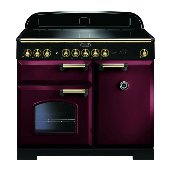
Cooker Overview ArtNo.025-0005 - Overview - 90 induction - 2 button clock & GO grill Fig. 2.1 This image is for illustrative purpose Your 90 induction cooker (Fig. 2.1) has the following features: Fig. 2.2 5 induction cooking zones Control panel A glide-out grill Main programmable fan oven Tall fan oven... -
Page 14: Pan Detector
Make sure that the base of the pan is clean and dry to prevent Fig. 2.4 any residue burning onto the hob panel. This also helps prevent scratches and deposits. Max: 1.85 kW Max: 1.85 kW Max: 1.85 kW Max: Max: Max: Boost: 2.5 kW... -
Page 15: Residual Heat Indicator, H
Residual Heat Indicator, H Auomatic Heat-up Time at Power Level 100% (min:sec) After use, a cooking zone will remain hot for a while as heat 0:48 dissipates. When a cooking zone is switched off the residual heat indicator symbol [H ], will appear in the display. This 2:24 shows that the cooking zone temperature is above 60 °C and 3:50... -
Page 16: Low Temperature Setting, L1/L2
Low Temperature Setting, L1/L2 Maximum Operating Time Power Level This function should only be used when heating from cold. 2 hours L1 and L2 6 hours Each cooking area is equipped with 2 low temperature settings: 6 hours 5 hours •... -
Page 17: Overheat Function
Overheat Function Fig. 2.9 This function identifies when the temperature of the pan rises rapidly and works to maintain a safe level of pan temperature. It should not interfere with normal cooking. Cookware with bases that become distorted (Fig. 2.2) when heated may interfere with the operation of the Overheat Function. -
Page 18: The Ovens
The Ovens Fig. 2.12 The clock must be set to the time of day before the programmable oven will work. See the following section on ‘The Clock’ for instructions on setting the time of day. References to ‘left-hand’ and ‘right-hand’ ovens apply as Fan oven viewed from the front of the appliance. -
Page 19: Accessories
Rear stop Rear stop Supplied with the Infusion, not available on the Classic and Professional+. As well as standard shelves, the left-hand oven is supplied with a set of runners for a glide-out oven shelf. To fit the glide-out shelf, hook the front of the shelf onto the runners as shown (Fig. -
Page 20: 3. 2 Button - Rotary Clock
3. 2 Button - rotary clock The clock must be set to the time of day before the oven Fig. 3.1 ArtNo.300-0005 2BC will work. minute minder setting Setting the Clock Once the cooker is connected and switched on, the display will start to flash. - Page 21 To stop the oven at a specific time of day Fig. 3.5 You have set the required temperature and function mode and you would like the oven to automatically stop. TOP TIP Make a note of the current time so you do not forget. Turn the Timer (A) knob to the Stop Time (G) setting.
- Page 22 To start and stop the oven automatically Fig. 3.9 The timer allows you to automatically start and stop by a combination of the length of the cooking time and the stop time. Giving you the flexibility to cook casseroles etc while you are out.
-
Page 23: Button Clock
3 Button clock Using the clock Fig. 4.1 You can use the clock to turn the programmable oven on and off. The clock must be set to the time of day before the oven will work. NOTE: When using the timer functions, first set the clock as ArtNo.306-0001 - 3-button clock required before setting the oven temperature. - Page 24 When the ‘stop time’ is reached an alarm will sound and Fig. 4.7 the oven will stop working. The word ‘AUTO’ will flash on the display (Fig. 4.6). Press any button to stop the alarm and return to manual cooking. If the alarm is not stopped, it will stop ArtNo.306-0001 - 3-button clock automatically after 7 minutes.
-
Page 25: Cooking Tips
Cooking tips Using Your Induction Cooker General oven tips If you have not used an induction cooker before please be The wire shelves should always be pushed firmly to the back aware of the following: of the oven. • Make sure that the pans you have or buy are suitable Baking trays with food cooking on them should be placed for use on the induction hob. -
Page 26: Cooking Table
Cooking Table The oven control settings and cooking times given in the table below are intended to be used as a Top (T) guide only. Individual tastes may require the temperature to be altered to provide a preferred result. ArtNo.050-0007 Centre (C) Oven shelf positions Food is cooked at lower temperature in a fan oven than in a conventional oven. -
Page 27: Cleaning Your Cooker
Cleaning your cooker Isolate the electricity supply before carrying out any Fig. 7.1 major cleaning. Then allow the cooker to cool. NEVER use paint solvents, washing soda, caustic cleaners, biological powders, bleach, chlorine based bleach cleaners, coarse abrasives or salt. DO NOT mix different cleaning products –... - Page 28 Grill Fig. 7.2 ArtNo.331-0003 Grill frame out, no pan The grill pan and trivet should be washed in hot soapy water. After grilling meats or any foods that soil, leave to soak for a few minutes immediately after use. Stubborn particles may be removed from the trivet using a nylon brush.
- Page 29 Glass fronted door panels Fig. 7.5 The oven door front panels can be taken off so that the glass panels can be cleaned. Move the cooker forward to gain access to the sides (see the ‘Moving the Cooker’ section under ‘Installation’).
- Page 30 Cleaning table Cleaners listed (Table 7.1) are available from supermarkets or electrical retailers as stated. For enamelled surfaces use a cleaner that is approved for use on vitreous enamel. Regular cleaning is recommended. For easier cleaning, wipe up any spillages immediately. Hotplate Part Finish...
-
Page 31: Troubleshooting
Troubleshooting DocNo.050-0001 - Troubleshooting - Induction GENERIC Interference with and repairs to the hob MUST NOT The cooling fan be carried out by unqualified persons. Do not try The induction hob incorporates a cooling fan. This cooling to repair the hob as this may result in injury and fan is active when either the grill or the oven(s) are on. - Page 32 The oven light is not working Fig. 8.1 The bulb has probably blown. You can buy a replacement bulb (which is not covered under the guarantee) from most electrical stores. Ask for a 40 W – 230 V halogen lamp (G9) (Fig. 8.1). Before removing the existing bulb, turn off the power supply and make sure that the oven is cool.
-
Page 33: Installation
Appliance Serial Number ArtNo.330-0001 - Grill pan Safety Requirements and Tall oven shelves and shelf supports Plinth (Classic and Infusion) Regulations This cooker must be installed in accordance with the relevant instructions in this booklet, with the relevant national and local regulations, and with the ArtNo.000-0010 Tall oven shelves... -
Page 34: Positioning The Cooker
INSTALLATION Check the appliance is electrically safe when you have finished. Positioning the Cooker Fig. 9.1 Fig. 9.1 and Fig. 9.2 show the minimum recommended distance from the cooker to nearby surfaces. 75 mm min 650 mm min 75 mm min The cooker should not be placed on a base. -
Page 35: Lowering The Two Rear Rollers
INSTALLATION Check the appliance is electrically safe when you have finished. Lowering the Two Rear Rollers Fig. 9.5 To adjust the height of the rear of the cooker, first fit a 13 mm spanner or socket wrench onto the hexagonal adjusting nut (Fig. -
Page 36: Electrical Connection
INSTALLATION Check the appliance is electrically safe when you have finished. Electrical Connection Current Operated Earth Leakage Breakers The combined use of your induction cooker and other The cooker must be installed by a qualified electrician, in domestic appliances may cause nuisance tripping, so we accordance with the relevant national and local regulations. -
Page 37: Final Fitting
Hook the central keyhole over the central screw. Twist and fit each end keyhole over their respective screws. Tighten the fixing screws (Fig. 9.13). Fitting the 2-piece Plinth (Classic and Infusion) Fit the inner plinth to the bottom front of the cooker using Fig. 9.14 the 4 screws provided (Fig. -
Page 38: 10. Circuit Diagrams
10. Circuit Diagrams Earth On Terminal Block N(6) On Terminal Block N(4) INDUCTION UNIT DISPLAY L(2) L(3) w/br w/br On Terminal Block INTERFACE BOARD w/br w/br w/br The connections shown in the circuit diagram are for single-phase. The ratings are for 230 V 50 Hz. Code Description Code Colour Left-hand front element... - Page 39 Fan Oven P095199 P095199 P095199 The connections shown in the circuit diagram are for single-phase. The ratings are for 230 V 50 Hz. Code Description Code Description Code Colour Grill energy regulator Clock Blue Grill front switch Cooling fan Brown Grill elements Oven light switch Black...
-
Page 40: 11. Technical Data
Total height Min 905 mm Max 930 mm Total width 900 mm Total depth (Classic) 608 mm excluding handles, 670 mm including handles Total depth (Infusion) 608 mm excluding handles, 656 mm including handles Total depth (Professional+) 608 mm excluding handles, 645 mm including handles... - Page 41 Classic 90 Induction 670 DEPTH INCLUDING HANDLES 608 DEPTH EXCLUDING HANDLES Infusion 90 Induction 656 DEPTH INCLUDING HANDLES...
- Page 42 Professional + 90 Induction 645 DEPTH INCLUDING HANDLES DEPTH EXCLUDING HANDLES...
- Page 43 Hotplate Efficiency Data Brand Falcon Model Identification Classic Infusion Professional+ Size Type Induction Type of Hob Induction Number of electric zones Zone 1 - Ø cm 18.5 Heating Technology Energy Consumption (ECElectric cooking) - Wh/kg Zone 2 - Ø cm 15.5...
- Page 44 Oven Data Brand Falcon Model identification Classic Mass Model identification Infusion Mass Model identification Professional+ Mass Type of oven Electric Number of cavities Left-hand Efficiency Fuel type Electric Cavity type Fanned Power - conventional Power - forced air convection Volume...
- Page 45 NOTE...
- Page 46 NOTE...
- Page 47 NOTE...
- Page 48 Clarence Street, Royal Leamington Spa, Warwickshire, CV31 2AD, England. www.falconworld.com...
Need help?
Do you have a question about the Classic and is the answer not in the manual?
Questions and answers