Advertisement
Table of Contents
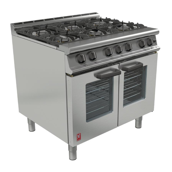
DOMINATOR PLUS
G3106 FAN ASSISTED RANGE
CAUTION: Read the instructions before using
this appliance
INSTALLATION and SERVICING
INSTRUCTIONS
This appliance must be installed and serviced by a competent person as stipulated by the Gas Safety (Installation
& Use) Regulations.
IMPORTANT
The installer must ensure that the installation of the appliance is in conformity with these instructions and National
Regulations in force at the time of installation. Particular attention MUST be paid to:
Gas Safety (Installation & Use) Regulations Health And Safety At Work etc. Act
Local and National Building Regulations Fire Precautions Act
Detailed recommendations are contained in Institute of Gas Engineers published documents: IGE/UP1, IGE/UP/2
BS6173 and BS5440
The appliance has been CE-marked on the basis of compliance with the Gas Appliance Directive for the Countries,
Gas Types and Pressures as stated on the data plate.
WARNING: TO PREVENT SHOCKS, ALL APPLIANCES WHETHER GAS OR ELECTRIC, MUST BE EARTHED.
On completion of the installation, these instructions should be left with the Engineer-in-Charge for reference during
servicing. Further to this, The Users Instructions should be handed over to the User, having had a demonstration of
the operation and cleaning of the appliance.
IT IS MOST IMPORTANT THAT THESE INSTRUCTIONS BE CONSULTED BEFORE INSTALLING AND
COMMISSIONING THIS APPLIANCE. FAILURE TO COMPLY WITH THE SPECIFIED PROCEDURES MAY
RESULT IN DAMAGE OR THE NEED FOR A SERVICE CALL.
PREVENTATIVE MAINTENANCE CONTRACT
In order to obtain maximum performance from this unit we would recommend that a maintenance contract be
arranged with SERVICELINE. Visits may then be made at agreed intervals to carry out adjustments and repairs. A
quotation will be given upon request to the contact numbers below.
WEEE Directive Registration No. WEE/DC0059TT/PRO At end of unit life, dispose of appliance and
any replacement parts in a safe manner, via a licenced waste handler.
U
nits are designed to be dismantled easily and recycling of all material is encouraged whenever
practicable.
Falcon Foodservice Equipment
HEAD OFFICE AND WORKS
Wallace View, Hillfoots Road, Stirling. FK9 5PY. Scotland.
SERVICELINE CONTACT
Phone: 01438 363 000
Fax: 01438 369 900
T100817 Ref 7
Advertisement
Table of Contents

Related Manuals for Falcon DOMINATOR PLUS G3106 Series


Summary of Contents for Falcon DOMINATOR PLUS G3106 Series
- Page 1 Falcon Foodservice Equipment HEAD OFFICE AND WORKS T100817 Ref 7 Wallace View, Hillfoots Road, Stirling. FK9 5PY. Scotland.
- Page 2 IMPORTANT INFORMATION Warranty Policy Shortlist Warranty does not cover :- Correcting faults caused by incorrect installation of a product. Where an engineer cannot gain access to a site or a product. Repeat commission visits. Replacement of any parts where damage has been caused by misuse. Engineer waiting time will be chargeable.
-
Page 3: Section 1 - Installation
SECTION 1 - INSTALLATION UNLESS OTHERWISE STATED, PARTS WHICH HAVE BEEN PROTECTED BY THE MANUFACTURER ARE NOT TO BE ADJUSTED BY THE INSTALLER. MODEL NUMBERS, NETT WEIGHTS and DIMENSIONS Width Depth Height Weight Model (mm) (mm) (mm) (kg) G3106 Take care when removing or installing cast iron components as they are heavy items. Pan Support –... - Page 4 ELECTRICAL SUPPLY 50Hz / 230V~ single phase with 13A supply. Unit must be electrically earthed. Motor rating: 200W Oven lamp rating: 25W Check that no damage has occurred to the appliance, power cable and plug face during transit. If damage has occurred do not use the appliance. Ensure that the mains power cable is routed free from the appliance to avoid damage.
-
Page 5: Section 2 - Assembly And Commissioning
Minimum gas flow to burner is governed by size of fixed by-pass screw aperture as follows. Natural gas Propane gas Model marked marked Open top SECTION 2 – ASSEMBLY and COMMISSIONING ASSEMBLY Note - The following paragraphs should be read as applicable to the unit being assembled. - Page 6 Figure 1 Figure 2 Figure 3 Figure 4 Fixings Figure 5...
-
Page 7: Commissioning The Appliance
COMMISSIONING THE APPLIANCE Important - Prior to operation, ensure that ALL packing material has been removed. 2.4.1 Setting Open Top Gas Pressure (Natural Gas Only) a) It is necessary to check gas pressure during commissioning and a suitable gauge must be connected to test point on RH side of supply manifold (situated behind front control facia). -
Page 8: Section 3 -Servicing And Conversion
SECTION 3 -SERVICING AND CONVERSION Important BEFORE ATTEMPTING ANY SERVICING, ENSURE ISOLATING COCK IS TURNED CANNOT INADVERTENTLY TURNED AFTER MAINTENANCE TASK, CHECK APPLIANCE TO ENSURE THAT IT PERFORMS CORRECTLY AND CARRY OUT ANY NECESSARY ADJUSTMENTS AS DETAILED IN SECTION 1. After carrying out any servicing or exchange of gas carrying component. - Page 9 3.1.4 Oven Burner - To Replace Injector (from front of oven Refer to Figure 9) Remove oven shelves and base plate. Undo fixings and remove burner plate. Undo fixings and remove pilot shield from back wall of combustion chamber. Remove burner by pushing it back out of mounting and draw it forward until pilot assembly and gas pipe can be removed from burner.
- Page 10 Undo nut that secures safety thermostat and remove thermostat from terminal box. Replace all parts in reverse order. 3.7.3 Thermostat Calibration The thermostat should not be calibrated. If temperature is out with specified tolerances, replace thermostat and return faulty thermostat to Falcon Quality Department.
-
Page 11: Fault Check List
OVEN FAN Remove oven back baffle. Remove fan impeller. Remove fan motor cover, located at rear of unit. Open electrics terminal box and disconnect motor wiring. Undo 4 fixings that secures motor to oven rear. Replace fan. Replace all other parts in reverse order. OPEN TOP Note - Plugs and bodies are machined in pairs and are not interchangeable. - Page 12 Circuit Diagram...
- Page 13 Wiring Diagram...
Need help?
Do you have a question about the DOMINATOR PLUS G3106 Series and is the answer not in the manual?
Questions and answers