Table of Contents

Related Manuals for Falcon 1 Series


Summary of Contents for Falcon 1 Series
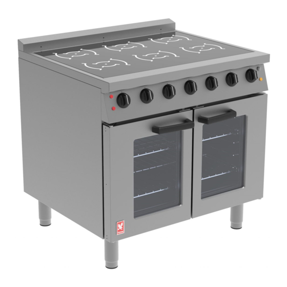
- Page 1 1 SERIES User, installation and servicing instructions 6 ZONE INDUCTION OVEN RANGE E161i & E163i Read these instructions before use DATE PURCHASED: MODEL NUMBER: SERIAL NUMBER: DEALER: SERVICE PROVIDER: T101029 Rev 2 Published: 16/12/2019...
- Page 2 Dear Customer Thank you for choosing Falcon Foodservice Equipment. This manual can be downloaded from www.falconfoodservice.com or scan here: IMPORTANT: Please keep this manual for future reference. Falcon Foodservice Equipment HEAD OFFICE Wallace View, Hillfoots Road, Stirling. FK9 5PY. Scotland.
- Page 3 SYMBOLS SCREWDRIVER SPANNER COOKING OIL GREASE WARNING SPARK IGNITION FLAME VIEWPORT ALLEN KEY IGNITER C SPANNER REMOVE DEVICE NON-IONISING PLUG REMOVER ELECTROMAGNETIC RADIATION...
- Page 4 Ensure the supply cord is routed free from the appliance to avoid damage. The appliance has been designed and approved to use Falcon kick plates; non Falcon kick plates could potentially adversely affect the performance of the appliance by restricting the air to the appliance.
- Page 5 Training and competence To help ensure the safe use of this appliance there is a requirement for you to provide whatever information, instruction, training and supervision as is necessary to ensure, so far as is reasonably practicable, the health and safety of all users. For further help and information on training and competence we would refer you the Health and Safety Executive website;...
-
Page 6: Table Of Contents
CONTENTS APPLIANCE INFORMATION ..................1 OPERATION ......................2 COMPONENT PARTS .................... 3 CONTROLS ......................4 USING THE APPLIANCE ..................5 HOB SETTINGS 1-9 ....................6 POWER BOOST ..................... 6 AUTOMATIC HEAT UP CONTROL (AHC): ............6 CONTROL LOCK FUNCTION ................6 PAN DETECTION .................... - Page 7 REAR COOLING FAN REMOVAL ................ 21 OVEN THERMOSTAT AND OVEN FAN SWITCH ..........21 OVEN LIGHT (PUSH BUTTON) ................22 OVEN ELEMENTS REMOVAL ................22 7.10 OVEN FAN REMOVAL ..................22 7.11 SAFETY AND OPERATION RELAY REMOVAL ..........22 7.12 OVEN AND REAR COOLING FAN CONTROL FUSES ........
-
Page 8: Appliance Information
1.0 APPLIANCE INFORMATION This appliance has been CE-marked on the basis of compliance with the relevant EU directives for the heat inputs, gas pressures and voltages stated on the data plate. A - Serial No B - Model No C - Flue Type D - Gas Category E - Gas Pressure F - Gas Type... -
Page 9: Operation
2.0 OPERATION IF GLASS-CERAMIC TOP IS CRACKED OR BROKEN IMMEDIATELY DISCONNECT APPLIANCE FROM POWER SUPPLY AND CONTACT YOUR SERVICE AGENT. THE AIR INTAKE FILTER MUST BE IN POSITION DURING OPERATION IT SHOULD BE CLEANED REGULARLY AND DO NOT OBSTRUCT AIR FILTER ENTRY BELOW. USERS MUST BE MADE AWARE THAT INDIVIDUALS FITTED WITH A PACEMAKER SHOULD CONSULT THEIR DOCTOR IF IN A CLOSE PROXIMITY TO THIS UNIT. -
Page 10: Component Parts
2.1 COMPONENT PARTS Left hand door Oven temperature control Right hand door Glass Drip tray Rear up stand Shelf Filter Hob zone control Oven shelf hanger... -
Page 11: Controls
2.2 CONTROLS Circuit 1 power neon (red) Oven temperature control Circuit 2 power neon (red) Only on E161i model Oven light switch Induction zone Indicator Induction zone digital display Induction control Oven heat neon (amber) -
Page 12: Using The Appliance
2.3 USING THE APPLIANCE 2.3.1 Ensure you use the correct size of pot. Ø120 – Ø250 <Ø120 2.3.2 Ensure the pots are central in the cooking zone. 2.3.3 Ensure you use the correct type of pot . 2.3.4 Ensure you use a clean flat bottom pan. -
Page 13: Hob Settings 1-9
2.4 HOB SETTINGS 1-9 2.4.1 Each cooking zone is controlled by a marked, variable control from 1 (lowest) to 9 (highest)..Table below gives guidance on the power for each setting and relevant time limits for each operation. Low temp Power Level hold Power % 100%... -
Page 14: Pan Detection
2.8 PAN DETECTION 2.8.1 This prevents the zones being turned on without a pan being present. It also switches the zone off as soon as a pan is removed. Also if the pan is made from the wrong type of material for induction equipment the digital display will read the no pan present symbol on the glass. -
Page 15: Cleaning And Maintenance
3.0 CLEANING AND MAINTENANCE When removing heavy items to aid cleaning or maintenance particular care should be taken. A manual handling risk assessment is the best way to determine the level of risk to anyone using or maintaining this equipment. To help with such an evaluation we have included the weights of individual components that may present significant risk. -
Page 16: Cleaning
3.1 CLEANING 3.1.1 Switch off appliance and cool down CLEAN THE AIR INTAKE FILTER REGULARLY. FAILURE TO CLEAN THE FILTER REGULARLY MAY CAUSE PROBLEMS WHICH WILL NOT BE COVERED BY WARRANTY. THE AIR INTAKE FILTER MUST BE IN-PLACE DURING OPERATION. DO NOT ATTEMPT TO REPAIR OR REPLACE ANY PART OTHER THAN THE AIR INTAKE FILTER. -
Page 17: Specification
4.0 SPECIFICATION 4.1 APPLIANCE WEIGHT TABLE APPLIANCE UNIT WEIGHT (kg) PACKED WEIGHT (kg) E161i E163i 4.2 TECHNICAL DATA TABLE(S) MODEL: E161i (SINGLE PHASE DUAL SUPPLY) CURRENT POWER MIN (A) @ MAX (A) @ ACTUAL (A) @ PHASE (kW) @ 230V 230V 230V 230V... -
Page 18: Dimensions / Connection Locations
5.0 DIMENSIONS / CONNECTION LOCATIONS 6.0 INSTALLATION Electrical Safety and Advice Regarding Supplementary Electrical Protection Commercial kitchens and foodservice areas are environments where electrical Appliances may be located close to liquids, or operate in and around damp conditions Or where restricted movement for installation and service is evident. The installation and periodic inspection of the appliance should only be undertaken by a qualified, skilled and competent electrician;... -
Page 19: Siting / Clearances
6.1 SITING / CLEARANCES CAUTION: WALLS CLOSER THAN 150mm TO THE APPLIANCE MUST BE NON COMBUSTIBLE. IF SUITING THE NECESSARY CLEARANCES TO ANY COMBUSTIBLE WALL MUST BE THE LARGEST FIGURE GIVEN FOR INDIVIDUAL APPLIANCES INSTRUCTIONS. -
Page 20: Assembly
6.2 ASSEMBLY 6.2.1 Position the appliance and level using feet adjusters as shown below. TAKE CARE WHEN MOVING AN APPLIANCE FITTED WITH CASTORS. -
Page 21: Electric Supply & Connection
6.3 ELECTRIC SUPPLY & CONNECTION The location of the electrical connection is as seen in section 5.0. this unit is suitable for AC supplies only. To install the mains cable, remove rear fan cover and terminal cover panel as shown below and feed the cable through the cable gland(s) and connect the mains supply to the terminal block(s). - Page 22 On Model E161i there is a requirement for two separate power supplies. The standard terminal arrangement is Single phase (2x 230V~). On this model there are two independent terminal blocks for each separate supply this must be wired as per the circuit diagram. Guide / example of E161I single phase dual power supply layout.
-
Page 23: Commissioning
6.4 COMMISSIONING Refer to section 2.0 for operation. If safety thermostat is activated, refer to section 7.1.3 to reset it. Carry out the following operation: 6.4.1 Turn on mains power supply on. 6.4.2 Ensure red neon(s) illuminates, 6.4.1 Place a pan suitable for induction cooker tops, filled with water, upon a cooking zone. The pan minimum diameter cannot be less than 120mm. -
Page 24: Servicing
7.0 SERVICING BEFORE ATTEMPTING ANY MAINTENANCE, ISOLATE THE APPLIANCE AT THE MAINS SWITCH AND TAKE STEPS TO ENSURE THAT IT IS NOT INADVERTENTLY SWITCHED ON. 7.1 CONTROL PANEL REMOVAL 7.1.1 Remove fixings at top and bottom of control panel 7.1.2 Open oven door and pull control panel forward whilst slightly easing the bottom edge up. -
Page 25: Control Switches Removal
7.3 CONTROL SWITCHES REMOVAL Hob switch detach as shown. 7.3.1 Remove control panel as detailed in Section 7.1 7.3.2 Remove switch connections and note wire arrangement. Pull off control knob. Undo fixings to release switch. 7.3.3 Fit replacement switch, ensuring that shake proof washers are fitted under fixing screws 7.4 INDUCTION GENERATOR REMOVAL 7.4.1 Remove control panel as detailed in Section 7.1... - Page 26 7.4.3 Un-fasten four screws on inner cradle assembly pull cradle forward and tilt down. 7.4.4 Disconnect generator wires from three way terminal block. Remove wiring, noting connection positions. 7.4.5 Unplug 8 Pole ribbon cable from PCB display board. Un-fasten two screws per generator.
-
Page 27: Hob Cooling Thermostat Removal
7.4.7 .Re-Fasten four screws on inner cradle assembly and ensure electrical connections are restored as per detailed in wiring diagram. 7.4.8 Remove stay and place back into centre fixing position, 7.4.9 Remove second stay whilst holding hob and place back into centre fixing position. Gently lower hob down and fix with three fixing screws. -
Page 28: Rear Cooling Fan Removal
7.6 REAR COOLING FAN REMOVAL Note: Two outer fans extract the hot air from inside the appliance. Centre Fan Induces clean air into the appliance. 7.7 OVEN THERMOSTAT AND OVEN FAN SWITCH 7.7.1 Remove control panel as detailed in Section 7.1. 7.7.2 Undo fixings from control panel 7.7.3 Remove wiring, noting connection positions 7.7.4 The combined switch and thermostat may now be removed from front panel. -
Page 29: Oven Light (Push Button)
7.8 OVEN LIGHT (PUSH BUTTON) 7.8.1 Remove control panel as detailed in Section 7.1. 7.8.2 Disconnect wires from switch. 7.8.3 Undo retaining nut and withdraw switch 7.8.4 Replace in reverse order. 7.9 OVEN ELEMENTS REMOVAL 7.9.1 Remove shelves and back baffle. Undo element fixing screw and withdraw into oven. 7.10 OVEN FAN REMOVAL 7.10.1 Remove oven shelves, back baffle and fan impellor (Note –... -
Page 30: Oven And Rear Cooling Fan Control Fuses
7.12 OVEN AND REAR COOLING FAN CONTROL FUSES 7.13 OVEN SAFETY TRIP SWITCH REPLACEMENT 7.13.1 An overheat safety trip is fitted to the oven chamber back panel. Accesses through the outer back panel cover plate (see warning note below). Warning If safety trip has been activated, reason for overheating must be identified before returning the appliance to service. -
Page 31: Oven Safety Trip Switch Replacement (Front Access)
7.13.3 If the switch is faulty remove by undoing two fixing screws on mounting plate. 7.13.4 Apply heat sink paste to underside of thermostat plate and re-attach new thermostat to mounting plate. 7.13.5 Electrical connections to be restored as per detailed in wiring diagram. 7.14 OVEN SAFETY TRIP SWITCH REPLACEMENT (FRONT ACCESS) 7.14.1 In any condition where space is restricted at appliance rear, the overheat safety trip may be accessed through the oven compartment by removal of pan support panel. -
Page 32: Circuit Diagrams
7.17 CIRCUIT DIAGRAMS 7.17.1 E161I Circuit diagram... - Page 33 7.17.2 E163I Circuit diagram...
-
Page 34: Wiring Diagrams
7.18 WIRING DIAGRAMS 7.18.1 E161I Wiring diagram... - Page 35 7.18.2 E163I Wiring diagram...
-
Page 36: Accessories
8.0 ACCESSORIES 9.0 FAULT FINDING 9.1 ERROR CODES 9.1.1 Most faults can be rectified by simply switching unit off for 10 seconds. After this time, turn power back on at mains supply. If fault continues to occur after such action then please refer to the table. - Page 37 FAULT POSSIBLE CAUSES REMEDY USER *ENG Check mains power is Unit will not turn ON No power to unit connected and turned on Check Fuse behind rear terminal cover panel Fuse has blown (section 7.12) and replace as necessary. Hob cooking zones will Change hob control knob ...
-
Page 38: Spare Parts
10.0 SPARE PARTS PART DESCRIPTION SPARES NUMBER Power neon red 730962010 Heat demand neon amber 730962040 Oven temperature control knob 535300004 Induction zone control knob 733990003 Oven operating thermostat 535420006 Coding switch 733990006 535420015 Oven safety thermostat Oven door seal assembly 535210001 Rear hob cooling fan 735400360... -
Page 39: Service Information
11.0 SERVICE INFORMATION It is recommended to have a maintenance contract with a local service provider. SERVICELINE CONTACT: (UK only) Phone: +441438 363 000 Warranty Policy Shortlist For our warranty policy please go to www.falconfoodservice.com...
Need help?
Do you have a question about the 1 Series and is the answer not in the manual?
Questions and answers