
Related Manuals for Falcon E1011


Summary of Contents for Falcon E1011
- Page 1 User, installation and servicing instructions REGENERATION OVEN E1011 Read these instructions before use DATE PURCHASED: MODEL NUMBER: SERIAL NUMBER: DEALER: SERVICE PROVIDER: T101045 Rev No: 9...
- Page 2 Dear Customer Thank you for choosing Falcon Foodservice Equipment. This manual can be downloaded from www.falconfoodservice.com or scan here: IMPORTANT: Please keep this manual for future reference. Falcon Foodservice Equipment HEAD OFFICE Wallace View, Hillfoots Road, Stirling, FK9 5PY, Scotland Tel: 01786 455200 WEEE Directive Registration No.
- Page 3 SYMBOLS SCREWDRIVER SPANNER COOKING OIL GREASE WARNING SPARK IGNITION FLAME VIEWPORT ALLEN KEY IGNITER C SPANNER REMOVE DEVICE PLUG REMOVER...
- Page 4 • This appliance may be discoloured due to testing. • These instructions are only valid if the country code appears on the appliance. If the code does not appear on the appliance, refer to the technical instructions for adapting the appliance to the conditions for use in that country. •...
- Page 5 PREVENTATIVE MAINTENANCE CONTRACT To obtain maximum performance from this unit regular servicing of the appliance should be undertaken to ensure correct operation, it is functioning as intended, and safe to use. We recommend servicing in accordance with SFG20 Maintenance Schedules and as a minimum, after 2,500 hours of use, or annually, whichever comes first and that a maintenance contract be arranged with an appointed service contact.
-
Page 6: Table Of Contents
CONTENTS APPLIANCE INFORMATION ..................1 OPERATION ......................2 COMPONENT PARTS & CONTROLS ..............2 USING THE APPLIANCE ..................3 CLEANING AND MAINTENANCE ................4 CLEANING AND MAINTENANCE ................5 SPECIFICATION ......................6 APPLIANCE WEIGHT TABLE ................6 TECHNICAL DATA TABLE(S) ................6 DIMENSIONS / CONNECTION LOCATIONS ............ - Page 7 7.16 FAN REMOVAL ....................22 7.17 CIRCUIT DIAGRAMS ..................23 7.18 WIRING DIAGRAMS ..................26 ACCESSORIES ....................... 29 LEG STAND SHELF RUNNERS ................29 FAULT FINDING ...................... 29 10.0 SPARE PARTS ......................30 11.0 SERVICE INFORMATION ..................31...
-
Page 8: Appliance Information
1.0 APPLIANCE INFORMATION These appliances have been UKCA/CE-marked based on compliance with the Gas Appliance Regulations/Product Safety and Metrology Regulations, Electrical and Electromagnetic Compatibility (EMC) Regulations/Directives for the Countries, Gas Types and Pressures as stated on the data plate. A - Serial No B - Model No C - Gas Category D - Gas Pressure... -
Page 9: Operation
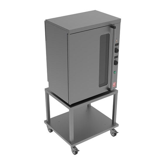
2.0 OPERATION 2.1 COMPONENT PARTS & CONTROLS Door On/off switch (Green) Control panel Mobile Leg Stand Oven heat neon (Amber) Oven shelf support Oven temperature control Oven shelf Oven timer control... -
Page 10: Using The Appliance
2.2 USING THE APPLIANCE The regeneration oven has been factory set for the cooking of pre-chilled and frozen bulk food meals. Warning: On dual supply models do not plug both supplies into adaptor, extension lead or 1x13amp double socket. Ensure both supplies are separate. -
Page 11: Cleaning And Maintenance
3.0 CLEANING AND MAINTENANCE When removing heavy items to aid cleaning or maintenance particular care should be taken. A manual handling risk assessment is the best way to determine the level of risk to anyone using or maintaining this equipment. To help with such an evaluation we have included the weights of individual components that may present significant risk. -
Page 12: Cleaning And Maintenance
Never plug both supplies into an adaptor, extension lead or a standard 13A double socket. Always ensure both supplies are separate. Do not plug any other appliance along with this appliance into a double socket. Only use Falcon approved spare parts, including 13A plug. -
Page 13: Specification
4.0 SPECIFICATION 4.1 APPLIANCE WEIGHT TABLE APPLIANCE UNIT WEIGHT (kg) PACKED WEIGHT (kg) E1011 4.2 TECHNICAL DATA TABLE(S) MODEL: E1011 (SINGLE PHASE DUAL SUPPLY) CURRENT POWER MIN (A) @ MAX (A) @ ACTUAL (A) PHASE (kW) @ 230V 230V 230V @ 230V 10.62... -
Page 14: Dimensions / Connection Locations
5.0 DIMENSIONS / CONNECTION LOCATIONS... -
Page 15: Installation
6.0 INSTALLATION Electrical Safety and Advice Regarding Supplementary Electrical Protection Commercial kitchens and foodservice areas are environments where electrical appliances may be located close to liquids or operate in and around damp conditions or where restricted movement for installation and service is evident. The installation and periodic inspection of the appliance should only be undertaken by a qualified, skilled and competent electrician;... -
Page 16: Sitting / Clearances
6.1 SITTING / CLEARANCES This appliance can be sited next to a combustible wall. 6.2 ASSEMBLY 6.2.1 Position the appliance and level using feet adjusters as shown below. TAKE CARE WHEN MOVING AN APPLIANCE FITTED WITH CASTORS. -
Page 17: Electric Supply & Connection
6.3 ELECTRIC SUPPLY & CONNECTION The location of the electrical inlet is as seen in section 5.0. This unit is suitable for AC supplies only. On Single phase 13A Model: the terminal arrangement is 2x 230V~ Unit is supplied with two separate 13amp moulded plugs. -
Page 18: Instruction To User
Carry out the following operation: 6.4.1 Turn mains power supply on. 6.4.2 Ensure green switch illuminates. 6.4.3 Switch green switch to the on position. 6.4.4 If the thermostat display is blank, depress thermostat control. 6.4.5 Turn temperature to 200°C. 6.4.6 Depress the thermostat control. 6.4.7 Ensure amber neon illuminates. -
Page 19: Servicing
7.0 SERVICING BEFORE ATTEMPTING ANY MAINTENANCE, ISOLATE THE APPLIANCE AT THE MAINS SWITCH AND TAKE STEPS TO ENSURE THAT IT IS NOT INADVERTENTLY SWITCHED ON. MAINTENANCE CHECK Regular servicing of the appliance should be undertaken to ensure correct operation, it is functioning as intended, and safe to use. We recommend servicing after 2,500 hours of use, or annually, whichever comes first. -
Page 20: To Replace Door Seal
7.2 TO REPLACE DOOR SEAL 7.2.1 Unclip door seal from frame. 7.3 TO REPLACE DOOR CATCH 7.3.1 Open door and remove two screws holding catch in place. Withdraw catch from door. 7.3.2 Replace in reverse order. 7.4 TO REPLACE DOOR STUD 7.4.1 Unlock nut and remove stud. -
Page 21: Temperature/Timer Control And Refitting
7.6 TEMPERATURE/TIMER CONTROL AND REFITTING 7.6.1 Remove side panel as per step 7.2. 7.6.2 Detach cables from module and remove as below. BEFORE ATTEMPTING ANY MAINTENANCE, ISOLATE THE APPLIANCE AT THE MAINS SWITCH AND TAKE STEPS TO ENSURE THAT IT IS NOT INADVERTENTLY SWITCHED ON. -
Page 22: Manual Programming Of Temperature Control
7.7 MANUAL PROGRAMING OF TEMPERATURE CONTROL in the event of the temperature module losing its parameters these settings can be manually set on the module using the following procedure: 7.7.2 /7.7.15 7.7.1 Make sure the device is off by pressing the knob for 2 seconds, then release 7.7.2 Push and hold in temperature knob for 4 seconds;... -
Page 23: Manual Programming Of Timer Control
7.8 MANUAL PROGRAMING OF TIMER CONTROL 7.8.2 /7.8.14 7.8.1 Make sure the device is off by pressing the knob for 2 seconds, then release. 7.8.2 Push and hold in temperature knob for 4 seconds; the display will show “PA”. 7.8.3 Push the knob once to select. 7.8.4 Rotate the knob within 15 seconds to “PAS”... -
Page 24: Neon/Led Removal
7.9 NEON/LED REMOVAL 7.9.1 Remove side panel as per step 7.2. 7.10 RELAY REMOVAL AND REFITTING 7.10.1 Remove side panel as per step 7.2. 7.10.2 Unplug wires from relay and remove both screws to release relay from panel. When re-fitting ensure all electrical connections are as per wiring diagram. BEFORE ATTEMPTING ANY MAINTENANCE, ISOLATE THE APPLIANCE AT THE MAINS SWITCH AND TAKE STEPS TO ENSURE THAT IT IS NOT INADVERTENTLY SWITCHED ON. -
Page 25: Operating Thermostat Removal
7.11 OPERATING THERMOSTAT REMOVAL 7.11.1 Remove right hand side panel as per step 7.2. 7.11.2 Detach two operating thermostat cables from temperature module. 7.11.3 Fix spanner on nut on inside of chamber and fix spanner on nut on outside of chamber and turn to remove operating thermostat. -
Page 26: Oven Safety Thermostat Reset
7.12.2 Fix Screwdriver on screws on outer panel and fix spanner on inside nuts, turn to release fixings from proximity switch. 7.13 OVEN SAFETY THERMOSTAT RESET 7.13.1 An overheat safety trip is fitted to the oven. Access is on the underside of the appliance as shown above. - Page 27 7.14.2 Loosen screws on phial guard; Lift off guard from the bracket exposing the bracket and the phial (as above). 7.14.3 Un-do the screws on the phial fixing bracket, remove from bracket and pass thermostat body thru the oven chamber via the phial clearance hole in the chamber (as above).
-
Page 28: Heating Elements Removal
7.15 HEATING ELEMENTS REMOVAL 7.15.1 Remove all shelves from oven chamber. 7.15.2 7.15.2 7.15.4 7.15.3 7.15.2 Loosen thumb screws on left hand shelf support and remove. 7.15.3 Remove screws on baffle and then remove. 7.15.4 Undo screws on element, once element is loose and with cables still attached feed cables through clearance slot (ensure not to tear or cut the cables when feeding through). -
Page 29: Fan Removal
7.16 FAN REMOVAL 7.16.3 7.16.4 7.16.2 7.16.6 7.16.5 7.16.1 Remove shelves, support and baffle from oven chamber. 7.16.2 Remove screws from rear panel. 7.16.3 Remove fixing nut from Impellor (note: Impellor nut is a left-hand thread). 7.16.4 Loosen bolts from inside of chamber. 7.16.5 Release motor box from rear of chamber. -
Page 30: Circuit Diagrams
7.17 CIRCUIT DIAGRAMS 7.17.1 SINGLE PHASE 230V 1N~DUAL SUPPLY (2x13A) - Page 31 7.17.2 SINGLE PHASE (32A)
- Page 32 7.17.3 THREE PHASE (16A)
-
Page 33: Wiring Diagrams
7.18 WIRING DIAGRAMS 7.18.1 SINGLE PHASE 230V 1N~DUAL SUPPLY (2x13A) - Page 34 7.18.2 SINGLE PHASE (32A)
- Page 35 7.18.3 THREE PHASE (16A/32A)
-
Page 36: Accessories
8.0 ACCESSORIES 8.1 LEG STAND SHELF RUNNERS 9.0 FAULT FINDING FAULT POSSIBLE CAUSES REMEDY USER *ENG Check mains power is ✓ Unit will not turn ON No power to unit connected and turned on ✓ Safety stat tripped Call engineer Oven will not operate ✓... -
Page 37: Spare Parts
10.0 SPARE PARTS PART DESCRIPTION SPARES NUMBER Amber Neon 730962040 Temperature Probe 730980000 Temperature Controller Module 730980001 Timer Control Module 730980002 Encoder 730980003 Control panel (For unit with rope door seal) 730980004 Control panel (For unit with silicone door seal) 730980013 Control knob 730980005... -
Page 38: Service Information
1. Model number – found on data plate 2. Serial number – found on data plate 3. Brief description of the issue To contact Falcon for a warranty issue dial (UK only) 01786 455 200 and select Warranty Issues from the menu.
Need help?
Do you have a question about the E1011 and is the answer not in the manual?
Questions and answers