Table of Contents
Advertisement
Quick Links
KW45B41Z-LOCUM
KW45B41Z-LOC Board User Manual
Rev. 2 — 21 March 2024
Agile number: 924-10008
Document information
Information
Keywords
Abstract
Content
KW45B41Z-LOCUM, KW45B41Z-LOC, KW45B41Z, Bluetooth LE 5.3, CAN FD
The KW45B41Z-LOC board is a highly configurable, low-power, cost-effective evaluation and
development platform for NXPKW45B41Z MCU.
User manual
Advertisement
Table of Contents

Related Manuals for NXP Semiconductors KW45B41Z-LOCUM


Summary of Contents for NXP Semiconductors KW45B41Z-LOCUM
- Page 1 Rev. 2 — 21 March 2024 User manual Agile number: 924-10008 Document information Information Content Keywords KW45B41Z-LOCUM, KW45B41Z-LOC, KW45B41Z, Bluetooth LE 5.3, CAN FD Abstract The KW45B41Z-LOC board is a highly configurable, low-power, cost-effective evaluation and development platform for NXPKW45B41Z MCU.
-
Page 2: Kw45B41Z-Loc Overview
KW45B41Z-LOCUM NXP Semiconductors KW45B41Z-LOC Board User Manual 1 KW45B41Z-LOC Overview The KW45B41Z-LOC board is a highly configurable, low-power, cost-effective evaluation and development platform for NXP KW45B41Z MCU, which is a low-power, highly secure, single chip wireless MCU based on Arm Cortex-M33 core. It offers an easy-to-use user interface with a virtual serial port and standard programming and run-control capabilities. -
Page 3: Block Diagram
KW45B41Z-LOCUM NXP Semiconductors KW45B41Z-LOC Board User Manual • KW45B41Z-LOC board • A USB cable • A bag with five jumpers 1.4 Block diagram Figure 1 shows the block diagram of KW45B41Z-LOC board. CR2032 MikroBUS I/O Headers 12 V 32.768 MHz... -
Page 4: Board Pictures
KW45B41Z-LOCUM NXP Semiconductors KW45B41Z-LOC Board User Manual Table 1. KW45B41Z-LOC features ...continued Board feature Target MCU feature used Description LPSPI One of the two LPSPI modules PCS0 connects to: (LPSPI1) with PCS0 used for LPSPI • 16 Mbit SPI NOR flash memory, which supports over-the-... -
Page 5: Top-Side View Of Kw45B41Z-Loc Board
KW45B41Z-LOCUM NXP Semiconductors KW45B41Z-LOC Board User Manual 1.6.1 Top-side view of KW45B41Z-LOC board u.FL (interrupt) (Wake-up) ANT_A (MCU-Link) (DC power jack) J1 (mikroBUS socket connector) U2 SP4T (CAN header) RF switch (target MCU) J3 (USB micro-B connector (u.FL) J2 (mikroBUS... -
Page 6: Bottom-Side View Of Kw45B41Z-Loc Board
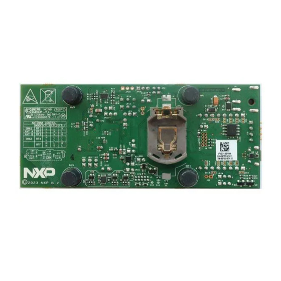
KW45B41Z-LOCUM NXP Semiconductors KW45B41Z-LOC Board User Manual Figure 3 shows the top-side view of the KW45B41Z-LOC board with jumpers highlighted. 1.6.3 Bottom-side view of KW45B41Z-LOC board Figure 4 shows the bottom-side view of the KW45B41Z-LOC board with battery holder (BT2) highlighted. -
Page 7: Jumpers
KW45B41Z-LOCUM NXP Semiconductors KW45B41Z-LOC Board User Manual Table 2. KW45B41Z-LOC connectors ...continued Part identifiers Connector type Description Reference section 2x5 pin header Arm JTAG (SWD) connector to connect an Section 3.2 external debug probe or external debug target J4 (DNP) 2x5 pin header... - Page 8 KW45B41Z-LOCUM NXP Semiconductors KW45B41Z-LOC Board User Manual Table 3. KW45B41Z-LOC jumpers ...continued Part Jumper Description Reference section identifier type the board is not functional since it is supplied from the V_BRD voltage node. Therefore RF section is disabled in this mode.
- Page 9 KW45B41Z-LOCUM NXP Semiconductors KW45B41Z-LOC Board User Manual Table 3. KW45B41Z-LOC jumpers ...continued Part Jumper Description Reference section identifier type The jumper needs to be populated when programming or debugging the board. 1x2 pin VDD_MEM supply enable shunt. When populated, this shunt...
-
Page 10: Push Buttons
KW45B41Z-LOCUM NXP Semiconductors KW45B41Z-LOC Board User Manual Table 3. KW45B41Z-LOC jumpers ...continued Part Jumper Description Reference section identifier type JP23 1x3 pin Target MCU pin selection jumper for mikroBUS socket connector J2 For more information header pin 1: on JP23 and JP24, see KW45B41Z-LOC board •... -
Page 11: Leds
KW45B41Z-LOCUM NXP Semiconductors KW45B41Z-LOC Board User Manual VDD_DCDC VDD_DCDC 10 kΩ TMP2_CH1 100 Ω PTC1 1000 pF TL1015AF160QG PTC1 PB SML-D14U2WT86C V_BRD JP11 10 kΩ WUU0_P12 PTC7 MTMM-102-06-G-S-236 LED_RST TP12 MCU_RST 1000 pF RST_TGTMCU_b TL1015AF160QG PTC7_WUU0_P12 PB TL1015AF160QG RST_SW VCC_IF_LINK... - Page 12 KW45B41Z-LOCUM NXP Semiconductors KW45B41Z-LOC Board User Manual P_LED P_LED V_BRD P_LED P_LED 100 Ω 100 Ω 510 Ω HDR 1X2 P_LED LED1 LED2 LED3 SML-D14U2WT86C LED_YEL LED_GREEN VDD_DCDC TMP1_CH0 LED1_R1 1 LED2_Y2 TMP1_CH5 PTC0 PTC6 0 Ω 0 Ω 100 Ω...
-
Page 13: Kw45B41Z-Loc Functional Description
KW45B41Z-LOCUM NXP Semiconductors KW45B41Z-LOC Board User Manual 2 KW45B41Z-LOC Functional Description This chapter describes the features and functions of the KW45B41Z-LOC board. You can use the functionality described in this chapter as a reference while designing your own target board. - Page 14 KW45B41Z-LOCUM NXP Semiconductors KW45B41Z-LOC Board User Manual P5V_CAN P3V3_LDO VBAT Secondary option Coin cell holder RB160M-30 V_LDO_OUT P3V3_BATT P3V3_BATT VOUT RB160M-30 RB160M-30 10 µF SMTU2450N-LF S8421-45R 10 µF 16 V 10 µF NCP1117ST33T3G 16 V FL_USB_5V0 FL_USB_5V0 Micro B RB160M-30 330 Ω...
- Page 15 KW45B41Z-LOCUM NXP Semiconductors KW45B41Z-LOC Board User Manual Table 6. KW45B41Z-LOC power supplies ...continued Power source Manufacturing part Power supply rail Description number • Supplies power to voltage translators U17 and U20 From FL_USB_5V0 or P5V (5 V) • Supplies power to LDO voltage regulator U4 P5V_CAN supply •...
-
Page 16: Power Modes
KW45B41Z-LOCUM NXP Semiconductors KW45B41Z-LOC Board User Manual Table 6. KW45B41Z-LOC power supplies ...continued Power source Manufacturing part Power supply rail Description number • Supplies power to reset button SW1 and reset button LED D3 • Can be used to supply power to interrupt button SW2 •... -
Page 17: Dc-Dc Inductor Options
KW45B41Z-LOCUM NXP Semiconductors KW45B41Z-LOC Board User Manual All the jumpers, except the jumper JP2 are 2-pin jumpers and an ammeter is connected to both 1 and 2 pins of the jumpers given in the Table 8 for the current measurement. -
Page 18: Clocks
KW45B41Z-LOCUM NXP Semiconductors KW45B41Z-LOC Board User Manual Automotive Maximum Isat Temperature Size Value Inductor type Manufacturer Part number qualified DC current (Ω) (mA) range (°C) (LxWxH) mm AEC-Q200 (mA) SMD shielded 1 μH MLZ2012A1R0WTD25 0.13 -55 to +125 2.2x1.45x1.05 Multilayer ferrite SMD shielded 1 μH... -
Page 19: Can Interface
KW45B41Z-LOCUM NXP Semiconductors KW45B41Z-LOC Board User Manual XTAL_32M XTAL_RF EXTAL_32M EXTAL_RF 0 Ω 32 MHz NX1612SA 32 MHz EXS00A CS14160 aaa-055248 Figure 10. 32 MHz clock circuit diagram Figure 11 shows the circuit diagram of the Y2 crystal that provides 32.768 kHz clock. Internal load capacitors provide the crystal load capacitance. -
Page 20: Lpuart Interface
KW45B41Z-LOCUM NXP Semiconductors KW45B41Z-LOC Board User Manual Table 10. KW45B41Z-LOC CAN connections CAN module Voltage translators Transceiver Connector levels of signals between speed CAN applications • 1: High-level CAN bus line connection the target MCU and CAN in the automotive industry, •... -
Page 21: Lpspi Interface
KW45B41Z-LOCUM NXP Semiconductors KW45B41Z-LOC Board User Manual Figure 14 shows the LPUART diagram of the KW45B41Z-LOC board. Target MCU mikroBUS socket LPUART0 connector J2 Debugger MCU Voltage LPUART1 MCU-Link translator KW45B41Z Figure 14. LPUART diagram Table 11 explains the KW45B41Z-LOC LPUART connections. - Page 22 KW45B41Z-LOCUM NXP Semiconductors KW45B41Z-LOC Board User Manual Slave SPI NOR flash memory Master PCS0 LPSPI1 Slave mikroBUS socket connector J1 KW45B41Z Figure 15. LPSPI diagram Table 12 explains the KW45B41Z-LOC LPSPI connections. Table 12. KW45B41Z-LOC LPSPI connections Slave device PCS0 16 Mbit (2 MB) SPI NOR flash memory U5 (AT25XE161D-MAHN-T) for over-the-air (OTA) programming or for storing non-volatile system data or parameters mikroBUS socket connector J1.
-
Page 23: Lpi2C Interface
KW45B41Z-LOCUM NXP Semiconductors KW45B41Z-LOC Board User Manual 2.6 LPI2C interface The target MCU (KW45B41Z) has two low-power inter-integrated circuit (LPI2C) modules, LPI2C0 and LPI2C1. The KW45B41Z-LOC board only supports LPI2C1 module. Figure 17 shows the KW45B41Z-LOC LPI2C diagram. mikroBUS socket... - Page 24 KW45B41Z-LOCUM NXP Semiconductors KW45B41Z-LOC Board User Manual U.FL connector Antenna A 2.4 GHz radio RF switch Antenna B KW45B41Z Control signals U.FL connector Figure 18. RF diagram Figure 18 shows the KW45B41Z-LOC RF diagram. VDD_PA_2G4 enable + 10 dBm RF output...
-
Page 25: Mikrobus Socket
KW45B41Z-LOCUM NXP Semiconductors KW45B41Z-LOC Board User Manual Table 14. RF I/O port selection ...continued Control signals RF mode RF I/O port CTRL3 CTRL2 CTRL1 High U.FL connector J8 High High All OFF None High High The KW45B41Z-LOC board supports programmable output power from -30 dBm to +10 dBm at the U.FL connectors. -
Page 26: Gpos
KW45B41Z-LOCUM NXP Semiconductors KW45B41Z-LOC Board User Manual The KW45B41Z-LOC mikroBUS socket supports different types of add-on boards, called click boards, which are plug and play solutions to add new functionality to the board design. A click board has a pair of 1x8 pin headers that connect to the two receptacles of a mikroBUS socket. -
Page 27: Mcu-Link Debug Probe
KW45B41Z-LOCUM NXP Semiconductors KW45B41Z-LOC Board User Manual 3 MCU-Link Debug Probe MCU-Link is a debug probe architecture jointly developed by NXP and Embedded Artists. The MCU-Link architecture is based on the LPC55S69 MCU, and it includes several mandatory and optional features. NXP uses MCU-Link on its evaluation kits (EVK boards). -
Page 28: Mcu-Link Host Driver And Utility Installation
KW45B41Z-LOCUM NXP Semiconductors KW45B41Z-LOC Board User Manual Table 18. Supported debug scenarios ...continued Debug scenario Feature support – Connect the external debugger to the target MCU SWD connector J5. The target MCU SWD interface is connected to the external debugger. • VCOM: MCU-Link VCOM feature can be used •... -
Page 29: Updating Mcu-Link Firmware
KW45B41Z-LOCUM NXP Semiconductors KW45B41Z-LOC Board User Manual The KW45B41Z-LOC board is now ready for the usage. If you use the board with MCUXpresso IDE version 11.3 or higher, you are notified in case a more recent firmware version is available for MCU-Link. If you use the board with a different IDE, ensure that the latest MCU-Link firmware version is installed on the board. -
Page 30: Using Mcu-Link With Mcuxpresso Ide
KW45B41Z-LOCUM NXP Semiconductors KW45B41Z-LOC Board User Manual Note: Other IDEs that support CMSIS-DAP or J-Link protocol can also use the MCU-Link debug probe; refer to the documentation for these IDEs for more information. 3.6.1 Using MCU-Link with MCUXpresso IDE The MCU-Link debug probe can be used with IDEs supported within the MCUXpresso ecosystem, such as MCUXpresso IDE, IAR Embedded Workbench, and MCUXpresso for Visual Studio Code (starting July 2023). - Page 31 KW45B41Z-LOCUM NXP Semiconductors KW45B41Z-LOC Board User Manual Table 20. LED D7 behavior ...continued MCU-Link mode LED D7 behavior Firmware Update (ISP) mode Lights up when MCU-Link (LPC55S69) boots in ISP mode Figure 20 shows the MCU-Link circuit diagram of the LED described in the...
-
Page 32: Software Support
KW45B41Z-LOCUM NXP Semiconductors KW45B41Z-LOC Board User Manual 4 Software support This section describes the software support for the KW45B41Z-LOC board. NXP provides a software development kit (SDK) for KW45B41Z-LOC board with several application examples. Additional information on KW45B41Z-LOC software support can be found in KW45B41Z-LOC RF Test Report (AN14098) and Channel Sounding Wireless Ranging Demo Application User Guide (CSWRDAUG). -
Page 33: Kw45B41Z-Loc Sdk Application Zip Package Structure
KW45B41Z-LOCUM NXP Semiconductors KW45B41Z-LOC Board User Manual Figure 23. NXP SDK and localization release build selection for given board 7. Select the highlighted preferences as shown in Figure Figure 24. SDK builder settings 8. To run the wireless applications, you must configure the category as Middleware for the following settings: •... -
Page 34: Hardware And Software Requirements
KW45B41Z-LOCUM NXP Semiconductors KW45B41Z-LOC Board User Manual Figure 25. SDK zip package folder structure Application related files are located at boards\kw45b41zloc\wireless_examples. Figure 26 shows the folder structure of wireless examples. Figure 26. Wireless examples folder structure The most important application for the KW45B41Z-LOC board testing is the wireless ranging application under the Bluetooth examples. - Page 35 KW45B41Z-LOCUM NXP Semiconductors KW45B41Z-LOC Board User Manual 1. Download the MCUXpresso IDE package from the NXP website link MCUXpresso Integrated Development Environment. Alternatively, you can use IAR Embedded Workbench. 2. Download the KW45B41Z-LOC SDK package. For more information, see Section 4.3.
-
Page 36: Board Errata
KW45B41Z-LOCUM NXP Semiconductors KW45B41Z-LOC Board User Manual 5 Board errata Table 22 summarizes all the known errata for the KW45B41B LOC board. Table 22. KW45B41Z LOC board errata summary Erratum Workaround Applicable Applicable schematics revision board revision mikroBUS header connectors J1 and... -
Page 37: Kw45B41Z-Loc Board Limitation
KW45B41Z-LOCUM NXP Semiconductors KW45B41Z-LOC Board User Manual 6 KW45B41Z-LOC board limitation The output power of the KW45B41Z radio has to be limited to comply with FCC requirements. The end user must determine the optimal radio output power needed to comply with the FCC requirements, based on their final circuit design. -
Page 38: Related Documentation
KW45B41Z-LOCUM NXP Semiconductors KW45B41Z-LOC Board User Manual 7 Related documentation Table 23 provides additional documents and resources that you can refer to for more information on the KW45B41Z-LOC board. Some of the documents listed below may be available only under a non-disclosure agreement (NDA). To request access to these documents, contact your local field applications engineer (FAE) or sales representative. -
Page 39: Acronyms
KW45B41Z-LOCUM NXP Semiconductors KW45B41Z-LOC Board User Manual 8 Acronyms Table 24 lists the acronyms used in this document. Table 24. Acronyms Acronym Description 4PDT Four-pole double-throw Bluetooth low energy Controller area network Do not populate Frequency-shift keying GFSK Gaussian frequency-shift keying... - Page 40 KW45B41Z-LOCUM NXP Semiconductors KW45B41Z-LOC Board User Manual Table 24. Acronyms ...continued Acronym Description Narrow band unit KW45B41Z-LOCUM All information provided in this document is subject to legal disclaimers. © 2024 NXP B.V. All rights reserved. User manual Rev. 2 — 21 March 2024...
-
Page 41: Revision History
KW45B41Z-LOCUM NXP Semiconductors KW45B41Z-LOC Board User Manual 9 Revision history Table 25 summarizes the revisions done to this document. Table 25. Revision history Document ID Release date Description KW45B41Z-LOCUM 21 March 2024 The following changes are made in this release: • Added the following sections: –... -
Page 42: Table Of Contents
J1 and J2 on the KW45B41Z LOC board are mirrored ..36 © 2024 NXP B.V. All rights reserved. For more information, please visit: https://www.nxp.com Date of release: 21 March 2024 Document identifier: KW45B41Z-LOCUM Document number: Agile number: 924-10008...
Need help?
Do you have a question about the KW45B41Z-LOCUM and is the answer not in the manual?
Questions and answers