Table of Contents
Advertisement
Quick Links
Advertisement
Table of Contents
Troubleshooting

Related Manuals for Skytron 1700


Summary of Contents for Skytron 1700
- Page 1 SURGICAL TABLE MAINTENANCE MANUAL MODEL 1700 Page 33...
-
Page 2: Table Of Contents
Indicates a possibility of personal injury. Indicates important facts or helpful hints. CAUTION Indicates a possibility of damage to equipment. Although current at time of publication, SKYTRON's policy of continuous development makes this manual subject to change without notice. 9/03 Page 27... - Page 3 • Check All Table Functions • Check Side Rails • Check Velcro • Lubricate Elevation Slider Assembly with SKYTRON Slider Grease P/N D6-010-89 • Tighten X-Ray Top Stand-Offs, Use Loc-tite • Lubricate Castors • Check brake pads for wear and inspect brake cylinders for proper operation.
- Page 4 EQUIPMENT LABELS AND SPECIFICATIONS INDICATES DANGEROUS VOLTAGE, 120 V, 60 Hz CLASS I DEFIBRILLATION PROOF, TYPE B EQUIPMENT- IPX4 RATED. INTERNALLY POWERED EQUIPMENT TYPE B EQUIPMENT PROTECTIVE GROUNDING. IN ORDER TO ENSURE PROPER GROUNDING RELIABILITY, THIS TABLE MUST BE CONNECTED TO A PROPERLY GROUNDED HOSPITAL GRADE OUTLET.
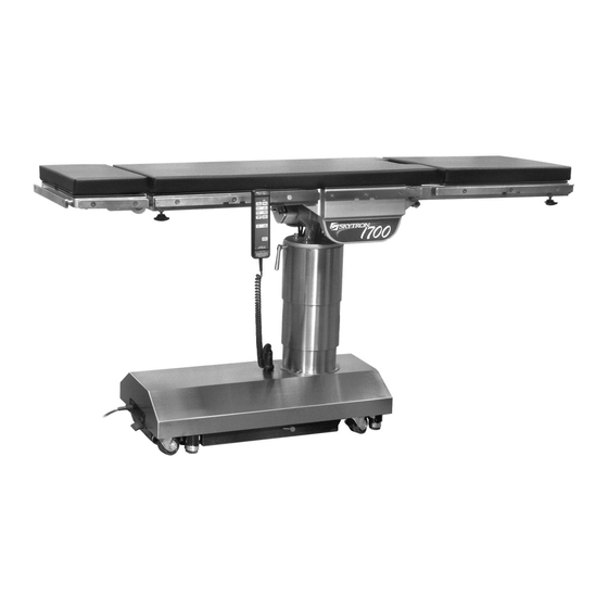
- Page 5 1700 Series General Purpose Surgical Table Specifications 14-1/2" 9-1/2" 21-1/2" 22" 22" 19-3/4" TOP VIEW 76" 60˚ 22" 90˚ 39" Max 29" Min 8-3/4" 35-1/2" 19" SIDE VIEW END VIEW Electrical Specifications 120 VAC, 60Hz, 300 Watts Power requirements Less than 100 micro amps...
-
Page 6: Section I Hydraulic System
SECTION I HYDRAULIC SYSTEM 1-1. General b. Motor/Pump Assembly - A positive displace- ment gear type pump provides the necessary oil Electro-Hydraulic System pressure and volume. The hydraulic system (with the exception of the c. Pressure Relief Valve - Provides an alternate oil hydraulic cylinders and hoses) is contained within path when the hydraulic cylinders reach the end of the base of the table. -
Page 7: Component Operation
1-2. Component Operation The main component of the valve is an adjustable a. Motor/Pump Operation spring loaded plunger that is pushed off from its seat by the oil pressure. The oil then flows back into the reservoir. See figure 1-4. Turning the adjust- The motor/pump assembly is a positive displace- ment nut clockwise increases the amount of oil ment gear type pump that provides the oil pressure... -
Page 8: Mini-Valves
c. Mini-Valves Also, by using this control method, it doesn’t matter The operation of the mini-valves is identical for all what size cylinder and piston is used because the table functions except the elevation and brake speed can be controlled by restricting the return oil. circuits. -
Page 9: Mini-Valve Right Port Activated
e. Mini-Valve Right Port Activated f. Mini-Valve Left Port Activated (See figure 1-6) (See figure 1-7.) Slave Cylinder Piston Moves to Left Slave Cylinder Piston Moves to Right Right Mini-Valve Port is Supply Line Left Mini-Valve Port is Supply Line Left Mini-Valve Port is Return Line Right Mini-Valve Port is Return Line OUTLET... -
Page 10: Hydraulic Cylinders (Slave Cylinders)
g. Hydraulic Cylinders (Slave Cylinders) There are several different types of hydraulic cylin- 2. Trendelenburg Cylinder Assembly - The ders used in the table that activate the control Trendelenburg and Lateral Tilt cylinders share a functions, all operate basically the same way. The common housing. -
Page 11: Elevation Cylinder Return Circuit
4. Elevation Cylinder - This single action cylin- der does not have hydraulic fluid on both sides of PISTON the piston. It depends on the weight of the table top assembly to lower it. OIL LINE The cylinder is set in the center of the elevation RETURN main column. -
Page 12: Brake System
i. Brake System When activated, the return hydraulic circuit oper- The brake system consists of the following compo- ates similar to the elevation cylinder return circuit. nents: (figure 1-15) Return springs inside the single action brake cylin- ders retract the brake pads and provide the pres- 1. -
Page 13: Hydraulic Adjustments
1-3. Hydraulic Adjustments a. Fluid Level. c. Pressure Relief Valve The pressure relief valve is adjusted by turning the The fluid level should be approximately 1/2" below the filler hole or gasket surface. If additional fluid is adjustment nut until the desired pressure is reached. needed, remove the filler vent cap with a phillips screwdriver and add fluid through this opening To adjust:... -
Page 14: Speed Controls
d. Speed Controls A pressure gauge should be used to set the speed The speed controls restrict the volume of oil return- of the back section and Trendelenburg control ing back to the reservoir thereby controlling the speed of each control function. functions. -
Page 15: Section Ii Hydraulic Troubleshooting
SECTION II HYDRAULIC TROUBLESHOOTING 2-1. Precautions Before attempting to troubleshoot any hydraulic Once the problem has been determined, concen- problem on the table, please read through the pre- trate on that particular hydraulic circuit or control function. cautions and notes below. Listed below are the hydraulic components that are common with all hydraulic circuits. -
Page 16: Elevation Diagnosis Chart
2-3. ELEVATION DIAGNOSIS CHART Problem Reason Pressure Relief Valve Not Set Properly Table will not elevate properly Low on Oil Spool Valve Not Centered Defective Pump Defective Mini-Valve Defective Solenoid or Wiring Defective Relay Box or Pendant Control Table will not descend properly Incorrect Speed Adjustment Bad Check Valve Spool Valve Not Centered... -
Page 17: Trendelenburg Diagnosis Chart
2-4. TRENDELENBURG DIAGNOSIS CHART Problem Reason Trendelenburg function moves improperly Incorrect Speed Adjustment Spool Valve Not Centered Bad Check Valves Low on Oil Pinched Hose Defective Mini-Valve Pressure Relief Valve Not Set Properly Bad Solenoid or Wiring Defective Relay Box or Pendant Control Defective or Dirty Check Valve Trendelenburg function chatters or loses position Oil Leakage in Circuit... -
Page 18: Lateral Tilt Diagnosis Chart
2-5. LATERAL TILT DIAGNOSIS CHART Problem Reason Lateral tilt function moves improperly Incorrect Speed Adjustment Spool Valve Not Centered Bad Check Valves Low on Oil Pinched Hose Defective Mini-Valve Pressure Relief Valve Not Set Properly Bad Solenoid Defective Relay Box or Pendant Control Lateral tilt function chatters or loses position Defective or Dirty Check Valves Oil Leakage in Circuit... -
Page 19: Back Section Diagnosis Chart
2-6. BACK SECTION DIAGNOSIS CHART Problem Reason Back Section function moves improperly Incorrect Speed Adjustment Spool Valve Not Centered Bad Check Valves Low on Oil Pinched Hose Defective Mini-Valve Pressure Relief Valve Not Set Properly Bad Solenoid Defective Relay Box or Pendant Control Back Section function chatters or loses position Defective or Dirty Check Valves Oil Leakage in Circuit... -
Page 20: Leg Section Diagnosis Chart
2-7. LEG SECTION DIAGNOSIS CHART Problem Reason Leg function moves improperly Incorrect Speed Adjustment Spool Valve Not Centered Bad Check Valves Low on Oil Pinched Hose Defective Mini-Valve Pressure Relief Valve Not Set Properly Bad Solenoid Defective Relay Box or Pendant Control Leg function chatters or loses position Defective or Dirty Check Valves Oil Leakage in Circuit... -
Page 21: Brake Circuit Diagnosis Chart
2-8. BRAKE CIRCUIT DIAGNOSIS CHART Reason Problem Emergency Brake Release Valve Open or Defec- Brakes will not set properly tive Spool Valve Not Centered Bad Check Valve NOTE Low on Oil Pressure Relief Valve Not Set Properly If brakes have been released with the Pinched Hose Emergency Brake Release Valve, Defective Mini-Valve... -
Page 22: Flexible Hose Identification And Placement
2-9. Flexible Hose Identification and Placement The following figure shows the correct placement of the flexible hydraulic hoses used in the table and their respective number codes. TREND SECTION BACK SECTION LATERAL TILT ELEVATION Figure 2-7. Flexible Hose Placement Page 17... -
Page 23: Section Iii Electrical System
SECTION III ELECTRICAL SYSTEM 3-1. General 3-2. Components The complete electrical system (with the excep- Refer to figure 3-1 for the relationship of the elec- tion of the hand-held pendant control) is contained trical components. within the base of the table. The pump motor and the hydraulic valves are controlled electrically with a. - Page 24 2 PIN PENDANT COIL 120 VAC CONNECTORS CONTROL MINI-VALVES PENDANT BASE CONNECTOR RELAY BOX CN2A CN2B CN15 MOTOR/PUMP ASSEMBLY CAPACITOR POWER DPST MAIN CORD POWER SWITCH CONNECTOR (2) FUSE 10AMP POWER CORD Figure 3-1. 1700 Electrical Circuit Block Diagram Page 19...
-
Page 25: Section Iv Electrical System Troubleshooting
SECTION IV ELECTRICAL SYSTEM TROUBLESHOOTING 4-1. Troubleshooting Notes 1. Plug the power cord into the 120VAC power The basic operation of each component will be supply (wall receptacle) and turn ON the main defined along with a drawing and explanation on switch. -
Page 26: Pendant Control
If the correct readings are obtained, this part of the circuit is okay and the problem may be the Pendant Control circuit board or the Relay Box. Contact SKYTRON if all tests performed indicate that the problem is located in the Pendant Control. PIN NO. -
Page 27: Solenoids
If all tests have wall receptacle and Power Switch turned ON. been conducted and it appears that the Relay Box is faulty, contact SKYTRON. 2. Disconnect the motor connector. All other connectors should be connected. Test connectors 4-5. - Page 28 a. Solenoid Test c. Test Results: The following tests check the voltage applied to the If you do not receive the correct voltage, the prob- solenoids and the resistance of the solenoid coil. lem could be in the wires leading to connectors. The problem could also be in the relay box or the NOTE Pendant Control (refer to appropriate section for...
- Page 29 BLUE BLUE WHITE/BLUE BLUE BLUE WHITE/BLUE BROWN BLUE BLUE WHITE/BLUE ORANGE BLUE BLUE WHITE/BLUE WHITE/BROWN BLUE BLUE WHITE/BLUE WHITE/GREY BLUE BLUE WHITE/BLUE BLACK/WHITE LOCK CN2B LAT. BACK ELEV. TREND BRAKE TILT SECT. SECT. LOCK CN2A BLUE BLUE WHITE/BLUE WHITE/BLACK BLUE BLUE WHITE/BLUE GREY...
-
Page 30: Motor/Pump Assembly
4-6. Motor/Pump Assembly The electric motor is a capacitor start type with a 3. Use a voltmeter capable of measuring 120 rating of 120 VAC, 200 watts. The field windings VAC and measure the following connector pins in are protected with a thermal protector that will open the connector. - Page 31 e. Test Results: The meter needle should move up scale and then back down to infinity. This would indicate that the capacitor is storing an electrical charge. NOTE The capacitor may have to be dis- charged first (by shorting pins 2 and 3 together) before you will be able to see the ohmmeter needle swing up the scale.
- Page 32 Page 28...
- Page 33 5000 36th Street S.E., Grand Rapids, MI 49512 1-800-SKYTRON or 1-616-957-0500 • FAX 1-616-957-5053 Page 32...
Need help?
Do you have a question about the 1700 and is the answer not in the manual?
Questions and answers