
Subscribe to Our Youtube Channel
Related Manuals for Enwork Odyssey


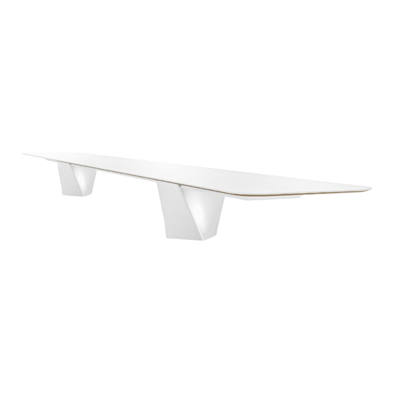
Summary of Contents for Enwork Odyssey
- Page 1 P A R T N U M B E R S A B X X X C O N F E R E N C E TA B L E S TI0082 Odyssey Conference Table Installation Guide – Rev 02.23...
- Page 2 1 — T O O L S A N D S U P P L I E S R E Q U I R E D Drill Hex Head Driver Square Head Driver Philips Head Driver Level Philips Screw Driver Combination Wrench Tape Measure Dead Blow Hammer Ratchet Socket Utility Knife Marker TI0082 - Odyssey Table Installation Instructions...
- Page 3 Serrated Flange Bolt Socket head Cap Screw Flathead Screw 1/4-20 Hex Nut 1/4-20 Nylock Hex Nut Washer Wood Dowel Zipbolt Surface Connector Clear Rubber Bumper, .375-16 x 1.25" .375-16 x 2.25" Adhesive Backed Bolt Bolt TI0082 - Odyssey Table Installation Instructions...
- Page 4 Base Leg (SAM-2006-x) #6-18 x .50" #10-24 x .50" Draw Plate 1 Draw Plate 2 Philips Philips (EAM-1000-1) (EAM-2000) Embedded Brace Top Connection Bracket Base Bottom Assembly Top Plate Assembly (NZBRACEx) (EAM-1024) (SAM-2004-x) (SAM-2003-x) TI0082 - Odyssey Table Installation Instructions...
- Page 5 2 — I N C L U D E D P A R T S A N D F A S T E N E R S Base Shroud Right Extrusion (EAA-2002-x-R) Left Extrusion (EAA-2002-x-L) Mid Extrusion (SAX-1092-x) OR (EAA-2003-x-R) OR (EAA-2003-x-L) (EAA-2002-x-M) C-Channel (EAM-1001-xx) TI0082 - Odyssey Table Installation Instructions...
- Page 6 Line up (1) Base Leg (SAM-2006-x) with the inside Carefully slide the Base Shroud(SAX-1092-x) over the connection holes on the Base Bottom Assembly. Base Leg assembly, until it covers the Assembly. Secure together with (4) .375-16 x 1.25" bolts. TI0082 - Odyssey Table Installation Instructions...
- Page 7 (4) 10-24 x ½ bolt. When the base assemblies are completed, place them in there final position. Note: If there are the access doors present they should face to the inside. TI0082 - Odyssey Table Installation Instructions...
- Page 8 .50". and finger tighten. Repeat for all Extrusion. facing up and the opening of the C facing outside. Note: Do not tighten the bolts at this time Note: Do not tighten the bolts at this time TI0082 - Odyssey Table Installation Instructions...
- Page 9 Note: Depending on table length, Left & Right Extrusions may be assembled at this point. Note: The extrusions must be aligned and square before they are fully tightening. Adjust as necessary while tightening. TI0082 - Odyssey Table Installation Instructions...
- Page 10 (3) .375-16x 2.25" bolts. middle extrusion assembly, shown right. Repeat process for the other end of the table. TI0082 - Odyssey Table Installation Instructions...
- Page 11 Insert the this assembly into the inside of the extrusions Brackets along the length of the extrusion. There will be 2 for every Top Connection Do not tighten yet. These may need to be Bracket (EAM-1024). repositioned later in the assembly process. TI0082 - Odyssey Table Installation Instructions...
- Page 12 (4) 375-16 x .50" bolts, and (4) .375-16 Square Nuts. Press the end cap in all the way tight against the end of the extrusion. Insure the back side of the cap is flush with the end of the extrusion. Fully tighten TI0082 - Odyssey Table Installation Instructions...
- Page 13 Place a level on the beam between the 2 Levelers are accessible through the bases and level the table length first. access hole on the tops of the base. Place a level spanning both beams and level the table across it’s depth. TI0082 - Odyssey Table Installation Instructions...
- Page 14 Connection Bracket and any power unit/cutouts. the Top Connection Bracket and “12 x 1" screws. Location of the Top Connection Bracket can be adjusted as needed. Tighten all of the brackets to the extrusion at this time. TI0082 - Odyssey Table Installation Instructions...
- Page 15 1.800.815.7251 enwork.com 12900 Christopher Dr. Lowell, MI 49331 Specifications subject to change without notice. Rev 02.2023...
Need help?
Do you have a question about the Odyssey and is the answer not in the manual?
Questions and answers