
Related Manuals for ADTRAN DSU III TDM


Summary of Contents for ADTRAN DSU III TDM
- Page 1 &57"+++"6&/ &CVC"5GTXKEG"7PKV 2CTV"0WODGT"3422285.3 &QEWOGPV"0WODGT"83422285.3/42# #RTKN"3;;;...
- Page 2 Trademarks: DATAPATH is a registered trademark of CAE electronics and is used by Northern Telecom under license. 901 Explorer Boulevard P.O. Box 140000 Huntsville, AL 35814-4000 (256) 963-8000 © 1999 ADTRAN, Inc. All Rights Reserved. Printed in U.S.A.
- Page 3 In the event of equipment malfunction, all repairs should be per- formed by ADTRAN. It is the responsibility fo users requiring ser- vice to report the need for service to their distributor or ADTRAN. See the inside back cover of this manual for information on contact-...
- Page 4 Shielded cables must be used with this unit to ensure compliances with Class A FCC limits. Changes or modifications to this unit not expressly approved by ADTRAN will void the user's authority to operate the equipment. CANADIAN EMISSIONS REQUIREMENTS This digital apparatus does not exceed the Class A limits for radio noise emissions from digital apparatus as set out in the interference-causing equipment standard entitled "Digital Apparatus,"...
- Page 5 CANADIAN EQUIPMENT LIMITATIONS Notice: The Canadian Industry and Science Canada label identifies certi- fied equipment. This certification means that the equipment meets certain telecommunications network protective, operational, and safety require- ments. The Department does not guarantee the equipment will operate to the user’s satisfaction.
- Page 6 SAVE THESE INSTRUCTIONS! ADTRAN YEAR 2000 (Y2K) READINESS DISCLOSURE ADTRAN has established a Year 2000 program to ensure that our prod- ucts and operations will correctly function in the new millenium. ADT- RAN warrants that all products meet Year 2000 specifications regardless of model or revision.
-
Page 7: Table Of Contents
Receipt Inspection ......... . . 2-1 ADTRAN Shipments Include ....... 2-1 Customer Provides . - Page 8 DSU and Network Status ........3-6 Current DSU III TDM Status .......3-6 Current DDS Network Status .
- Page 9 Loop Rate ..........6-1 61200063L1-20 DSU III TDM User Manual...
- Page 10 When Out of Service (OOS) ....... .9-4 DSU III TDM User Manual...
- Page 11 Appendix D. EIA-232 Connector ....... .D-1 Appendix E. Specifications Summary......E-1 61200063L1-20 DSU III TDM User Manual...
- Page 12 Index ............1 DSU III TDM User Manual...
-
Page 13: List Of Figures
Figure 3-3. DSU III TDM Front View ......3-10 Figure 3-4. DSU III TDM Rear View ......3-13 Figure 4-1. - Page 14 Figure 11-1. Dial Options Menu ....... . .11-1 Figure C-1. DSU III TDM to Modem Interconnect ....C-1 Figure D-1.
- Page 15 Table A-5. EIA-232 Pin Assignments for Adapter Cable... .A-5 Table B-1. Default Configuration for the DSU III TDM ... . B-2...
- Page 16 List of Tables DSU III TDM User Manual 61200063L1-20...
-
Page 17: Chapter 1. Introduction
Figure 1-1 on page 1-2 shows an example of a typical application using the DSU III TDM on a 64 kbps network. Each of the four DTE devices is al- lowed a portion of the dedicated circuit, not exceeding the allowable band- width of 60.8 kbps. -
Page 18: Dds Operation
64 kbps. The local exchange carriers provide the local loop service to DDS customers and may provide data for routing Inter- LATA to an interexchange carrier. In DDS mode, the DSU III TDM sup- ports the 56/64 kbps DDS service rate. -
Page 19: Dial Backup Operation
Contact your local telco provider to determine which services are avail- able for your location. The DSU III TDM equipped with a Switched 56 or ISDN module can auto- matically or manually back up all four ports in the event of a DDS circuit failure. -
Page 20: 2-Wire Switched 56 Backup Option
The default data rate for this option is 56 kbps. The 64 kbps data rate may be accessed using the Smart Dial String as described in the chapter Config- uring Dial Options on page 9-1. This option provides a U interface to the ISDN network. DSU III TDM User Manual 61200063L1-20... -
Page 21: Entering Dial Backup Mode
Panel on page 3-10 for more information on the key. Quick The following conditions can be enabled to cause the DSU III TDM to enter dial backup mode: Loss of Sealing Current Sealing current is a low voltage DC current provided by the central office (CO) to prevent corrosion of splices in copper wires used in the local loop. -
Page 22: Conditions For Returning To The Dds Circuit
Chapter 1. Introduction Conditions for Returning to the DDS Circuit The DSU III TDM can be configured to revert automatically to the DDS circuit from the dial backup mode or wait to be returned to the DDS circuit manually. Once the DSU III TDM enters dial backup mode, the unit polls the DDS circuit once every 100 ms to determine if the condition causing the DDS circuit failure has been corrected. -
Page 23: Warranty And Customer Service
Chapter 1. Introduction WARRANTY AND CUSTOMER SERVICE ADTRAN will replace or repair this product within five years from the date of shipment if it does not meet its published specifications or fails while in service. For detailed warranty, repair, and return information re- fer to the ADTRAN Equipment Warranty and Repair and Return Policy Procedure. - Page 24 Chapter 1. Introduction DSU III TDM User Manual 61200063L1-20...
-
Page 25: Chapter 2. Installation
UNPACK, INSPECT, POWER UP Receipt Inspection Carefully inspect the DSU III TDM for any damages that may have oc- curred in shipment. If damage is suspected, file a claim immediately with the carrier and contact ADTRAN Customer and Product Service (see the last page of this manual). -
Page 26: Customer Provides
1200063L8 for male to female) is available from ADTRAN. This cable converts the EIA-232 on the rear panel of the unit to V.35. The pinout for the V.35 conversion is shown in the appendix Pinouts on page A-1. -
Page 27: Network Connection
Chapter 2. Installation NETWORK CONNECTION Telco Connectors The DSU III TDM has two eight-position modular jacks labeled MAIN and BACKUP. The M connector provides connection to the dedicated (DDS) network. See Table on page A-2 for the connector's pin assignments. -
Page 28: Dte Connection
EIA-232 Connector on page D-1. The EIA-232 interface should be used only for speeds up to 19.2 kpbs. Speeds over 19.2 kpbs should use the V.35 adapter. DSU III TDM User Manual 61200063L1-20... -
Page 29: Configuration
Chapter 2. Installation CONFIGURATION The DSU III TDM is configured from the front panel. The DSU III TDM contains four different user profiles (sets of configurations options) that are stored in read-only memory. These profiles are listed in the appendix Configuration Profiles on page B-1. -
Page 30: Remote Command
Chapter 2. Installation Remote Command The DSU III TDM can be controlled remotely from another DSU III TDM. The Configuration (C ) menu allows the DSU III TDM remote config- ONFIG uration capability to be enabled or disabled. For more information see the chapter Configuration Overview on page 5-1. -
Page 31: Chapter 3. Operation
Chapter 3 MENU STRUCTURE The DSU III TDM uses a multilevel menu approach to access its many fea- tures. All menu operations are displayed in the LCD window. The opening menu is the access point to all other operations. There are... -
Page 32: Status
56K or 64K) on the first line. The DTE data rate and format (as selected in con- figuration) are shown on the second line. While this screen is displayed, the current port can be changed by pressing the desired port number on the key- pad. DSU III TDM User Manual 61200063L1-20... -
Page 33: Dial Backup Information
Chapter 3. Operation Dial Backup Information Type of Dial Backup Service The type of dial backup service installed in the DSU III TDM is indicated by one of the following messages DU DBU Status 2-Wire Switched 56 backup option installed. - Page 34 The network provider has activated the CSU Loopback (2-wire and 4-wire Switched 56). DBU Test Pattern The DSU III TDM is currently performing a test with a pattern. Waiting for Call The answering DSU III TDM is waiting on a call from the remote end.
-
Page 35: Multiplexer Status
• Bad or noisy telco circuit • Test in progress INV CFG (x=1-4) Normal Operation of the DSU III TDM PORTx requires that the local DTE R and DTE F ORMAT be the same as the remote options on a port by port basis. -
Page 36: Dsu And Network Status
Chapter 3. Operation DSU and Network Status Current DSU III TDM Status Possible messages indicating the current status of the DSU III TDM include the following: Data Mode In data mode, the data set ready (SR) and request to send (RTS) circuits are on, and the DSU III TDM is ready to send data. -
Page 37: Test
1, Configuring Dial Options on page 9-1, and Manual Command on page 10-1. Dial provides manual dialing functions. Key in a number to dial or select one of the ten stored numbers. See the chapter Dial Options on page 11-1 for more information. 61200063L1-20 DSU III TDM User Manual... -
Page 38: Basic Menu Travel
Chapter 3. Operation BASIC MENU TRAVEL Four function keys on the left side of the DSU III TDM keypad allow the vari- ous menu branches to be entered, exited, and scrolled through. The four func- tion keys are defined below:... -
Page 39: Figure 3-2. Example Of Basic Menu Travel
1= NETWORK OPT 1= LOOP RATE 3= CONFIG 2= DTE OPTIONS 2= CLOCK SOURCE 2= REMOTE 3= TEST OPTIONS 3= REMOTE CONFIG. 4= DIAL OPTIONS 5= MANUAL COMMAND Figure 3-2. Example of Basic Menu Travel 61200063L1-20 DSU III TDM User Manual... -
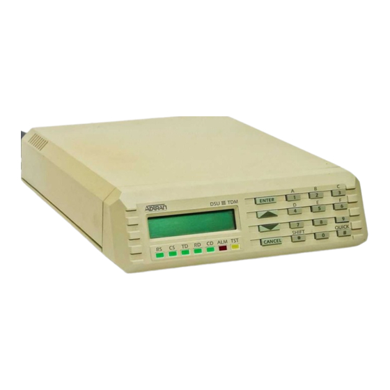
Page 40: Front Panel
Chapter 3. Operation FRONT PANEL The DSU III TDM faceplate is shown in Figure 3-3 . Descriptions of the display keys and LEDs located on the front panel follow the figure. DSU III TDM ENTER R D C D A L M T S T... -
Page 41: Quick
) or reverse ( Down Arrow Up Ar- ) pattern. LED Description The DSU III TDM has seven LED indicators: RS, CS, TD, RD, CD, ALM, and TST. These LEDs are identified as follows: 61200063L1-20 DSU III TDM User Manual 3-11... - Page 42 Open loop on network • No frame synchronization • Unit in dial backup • Problem on dial backup line TST: Test Mode This LED is active whenever the unit is in test mode. 3-12 DSU III TDM User Manual 61200063L1-20...
-
Page 43: Rear Panel
1 through PORT 4, used to connect to DTE equipment. The EIA-232 inter- face is provided on four standard DB-25 connectors. Pin assignments for the DTE and network connections are described in the appendix Pinouts on page A-1. The DSU III TDM rear panel is shown in Figure 3-4 . TELCO MAIN... - Page 44 Chapter 3. Operation 3-14 DSU III TDM User Manual 61200063L1-20...
-
Page 45: Chapter 4. Testing And Troubleshooting
Chapter 4 TEST OVERVIEW The DSU III TDM performs a variety of diagnostic functions that isolate portions of the circuit to identify the problem source. Tests may be initiat- ed and terminated from the front panel or the DTE interface. -
Page 46: Figure 4-1. Normal Operation Before Initiating Loopback Test
Chapter 4. Testing and Troubleshooting LOCAL TDM REMOTE TDM TELCO Figure 4-1. Normal Operation Before Initiating Loopback Test All diagnostic tests disrupt data flow. DSU III TDM User Manual 61200063L1-20... -
Page 47: Initiating A Test
2=TEST 1=LOCAL UNIT 3=DTE ONLY 4=DTE WITH TP 2=REMOTE UNIT 5=TEST PATTERN 3=DBU CONNECTION 6=SELF TEST Figure 4-2. Initiating a Test Once a test is initiated is displayed briefly followed by the S Please Wait screen. 61200063L1-20 DSU III TDM User Manual... -
Page 48: Test Status Display
ISPLAY TATUS menu provides the following options, which are available only after a test has been initiated: Exit Test Exits the current test and returns to the main menu. Display Status Reenters test display. DSU III TDM User Manual 61200063L1-20... -
Page 49: Figure 4-4. Complete Test Menu
2 = E M P T Y 2 = E N T E R D IA L # X X X X X X X X X X X Figure 4-4. Complete Test Menu 61200063L1-20 DSU III TDM User Manual... -
Page 50: Local Unit Diagnostics
Chapter 4. Testing and Troubleshooting LOCAL UNIT DIAGNOSTICS The local DSU III TDM can perform six different tests; see Table 4-1. Table 4-1. Test Selections Front Panel Description Display DTE & Loop (LL) TD/RD and RX/TX Loopbacks Loop Only (RT) -
Page 51: Dte & Loop (Ll)
DTE & LOOP (LL) Test Description The DTE & L test splits the DSU III TDM into two separate DTE and loop interface sections and then loops the receive data of each interface back to its respective transmit data. The DTE & L test provides a bidi- rectional loopback at the DSU/CSU. -
Page 52: Test Purpose
6=SELF TEST 2=TEST 2=REMOTE UNIT 3=DBU CONNECTION Figure 4-6. Initiating a DTE & Loop Test Interpreting Test Results A BERT tester must be used to interpret the test results of a DTE & L test. DSU III TDM User Manual 61200063L1-20... -
Page 53: Loop Only (Rt)
The L (RT) test allows the loop interface and a major portion of the DTE interface for the local DSU III TDM to be tested from the remote site over the actual communication circuit. Figure 4-7 illustrates the loop- back point and the signal paths for this test. -
Page 54: Initiating
Figure 4-8. Initiating a Loop Only Test Interpreting Test Results The Loop Only test is used for the purpose of looping the DDS circuit back to the telco. No test results are available from the local DSU III TDM. 4-10 DSU III TDM User Manual... -
Page 55: Dte Only
The DTE O test provides a method for testing both the DTE interface drivers and receivers of the local DSU III TDM. For this test, the DTE transmit data is connected to the DTE receive data at a point close to the physical DTE interface. -
Page 56: Test Purpose
• Verify integrity of the DTE interface. • Verify integrity of connection between DTE and DSU III TDM. Initiating Follow the menu path outlined in Figure 4-10 to initiate a DTE O test. -
Page 57: Dte With Test Pattern
Figure 4-11 illustrates the loop- back point and the data paths for this test. LOCAL TDM Error Inject Test Pattern Generator Test Pattern Detector Error Clear Figure 4-11. DTE with Test Pattern 61200063L1-20 DSU III TDM User Manual 4-13... -
Page 58: Test Purpose
100 octets: 0000 0000. Stress Pattern 3 Stress pattern with medium ones density. Continuous series of octets: 0011 0010. Stress Pattern 4 Stress pattern with low ones density. Continuous series of octets: 0100 0000. 4-14 DSU III TDM User Manual 61200063L1-20... -
Page 59: Interpreting Test Results
Chapter 4. Testing and Troubleshooting Interpreting Test Results During this test, the DSU III TDM displays: DTE WITH TP TST ERR=XX The first line of the display indicates the type of test being performed while the second line of the display indicates the number of errors accu- mulated by the test pattern detector. -
Page 60: Test Pattern
Chapter 4. Testing and Troubleshooting Test Pattern The T option converts the local DSU III TDM into a BERT tester ATTERN for the purpose of testing the DDS circuit. When this test is used, the remote DSU/CSU must be in loopback or transmitting a test pattern. Figure 4-13 illus- trates the data paths for this mode. -
Page 61: Test Purpose
6=SELF TEST 6=STRESS PTRN #4 2=REMOTE UNIT 3=DBU CONNECTION Figure 4-14. Initiating a Test Using a Test Pattern Interpreting Test Results During this test, the display should show the following: TST ERR = 00 61200063L1-20 DSU III TDM User Manual 4-17... -
Page 62: Self Test
Chapter 4. Testing and Troubleshooting Self Test The S verifies current operation of the DSU III TDM. It can be per- formed at any time and is recommended if there is any question about the DSU's health. Test Purpose To determine if the DSU is functioning properly. - Page 63 INVALID MUX CONFIG BLOCK If any messages other than P or I are dis- NVALID ONFIG LOCK played, contact ADTRAN technical support (see the last page in this man- ual). The I message is an indication that the multi- NVALID ONFIG LOCK plexer received invalid configuration information from the nonvolatile memory.
-
Page 64: Remote Unit Diagnostics
The test selections with test patterns use the internal pattern generator of the DSU III TDM to transmit and verify a test pattern over the DDS network; see Figure 4-16 on page 4-21. The remote unit is placed in RDL automatically. The DSU III TDM is capable of transmitting six test patterns with its built-in test pattern generator. -
Page 65: Data From Dte
DTE ports, depending on the physical connection. See Figure 4-16. REMOTE TDM LOCAL TDM Error Inject Test Pattern Generator TELCO Test Pattern Detector Error Clear Figure 4-16. V.54 Remote Digital Loopback w/Test Pattern 61200063L1-20 DSU III TDM User Manual 4-21... -
Page 66: Port Rdl
The other three ports function normally during this test. See Figure 4-17. REMOTE TDM LOCAL TDM Selected Port TELCO Figure 4-17. Port RDL Test Purpose Tests the local DSU, the DDS circuit, and the remote DSU. 4-22 DSU III TDM User Manual 61200063L1-20... -
Page 67: Initiating
Chapter 4. Testing and Troubleshooting Initiating Follow the menu path outlined in Figure 4-18 to place a remote DSU III TDM into loopback. 1=2047 PATTERN 1=LOCAL UNIT 2=511 PATTERN 2=TEST 3=STRESS PTRN #1 2=REMOTE UNIT 4=STRESS PTRN #2 5=STRESS PTRN #3... -
Page 68: Dbu Connection
Chapter 4. Testing and Troubleshooting DBU CONNECTION When the DSU III TDM is equipped with a dial backup option, the DBU C option appears as one of the T menu selections. This test allows NECTION the dial backup network to be tested while data is passing on the DDS. -
Page 69: Test Purpose
6=EMPTY 7=EMPTY 8=EMPTY 9=EMPTY A=EMPTY Figure 4-20. Initiating a DBU Connection Test Interpreting Test Results If the unit is functioning properly, the DSU III TDM displays: DBU TEST PATTERN TST ERR = 0000 61200063L1-20 DSU III TDM User Manual 4-25... -
Page 70: Troubleshooting
ADTRAN DSU/ CSUs. Messages from the DSU/CSU The DSU III TDM displays messages on the LCD display and LEDs concerning the status of the unit and the local loop. If the LED is on, one or more of Alarm the messages shown in Table 4-3 are displayed on the LCD. -
Page 71: Table 4-3. Messages From The Dsu/Csu
TEST FROM Telco activated a Telco is testing Wait until test is TELCO loopback to test circuit. complete or the DDS circuit. contact telco service provider. 61200063L1-20 DSU III TDM User Manual 4-27... - Page 72 Chapter 4. Testing and Troubleshooting 4-28 DSU III TDM User Manual 61200063L1-20...
-
Page 73: Chapter 5. Configuration Overview
The DSU III TDM contains four different user profiles (sets of configura- tions options) that are stored in read only memory (see Default Configura- tion for the DSU III TDM on page B-2). The unit is shipped from the factory with profile number 1 (default configuration) loaded into the current (non- volatile configuration) memory. - Page 74 Chapter 5. Configuration Overview volatile configuration) memory. The DSU III TDM is then configured with that profile every time power is turned on or until the unit is reset. The DTE R and D options must be configured ORMAT the same on both units for correct operation. For this reason, any...
-
Page 75: Chapter 6. Configuring Network Options
The unit should be set to the rate required by the DDS. The DSU III TDM supports loop rates of 56 and 64 kbps (shown in Figure 6-1). The default factory setting is 56 kbps. - Page 76 To prevent this, the S option should be selected for CRAMBLER both the local and remote DSU III TDM. DSU III TDM User Manual 61200063L1-20...
-
Page 77: Clock Source
5=MANUAL COMMAND Figure 6-2. Setting the Clock Source When operating on a DDS network, the timing should be F ETWORK On a point-to-point private network, one DSU III TDM must be set for , the other set for F ASTER ETWORK... -
Page 78: Remote Configuration
Chapter 6. Configuring Network Options Remote Configuration This option sets up the DSU III TDM to accept or reject remote configura- tion commands. Figure 6-3 shows the menu path for enabling/dis- abling remote configuration. The factory default setting is NABLED... -
Page 79: Chapter 7. Configuring Dte Options
The DTE O menu is used to select the configuration parameters that PTIONS control the operation of the DTE interface ports of the DSU III TDM. After selecting DTE O , specify the port to be configured. The DTE O... -
Page 80: Port Not Used
Figure 7-1. DTE Rate Options If a 64 kbps main DDS line is switched to a 56 kbps backup line, the DSU III TDM drops DTEs starting with port 4 until the maximum bandwidth is no longer exceeded. The most important DTE device should be connected to port 1. -
Page 81: Data Format
57.6 kbps for port 1. SYNCHRONOUS 1=NETWORK OPT. 1=DTE RATE 2=DATA FORMAT 1=ASYNCHRONOUS 1=LOCAL 2=SYNCHRONOUS 3=TX CLOCK 3=CONFIG 2=DTE OPTIONS 4=CS OPTIONS 2=REMOTE 5=CD OPTIONS 6=SR OPTIONS 3=TEST OPTIONS 4=DIAL OPTIONS 5=MANUAL COMMAND Figure 7-2. Selecting Data Format 61200063L1-20 DSU III TDM User Manual... -
Page 82: Transmit Clock
RANSMIT LOCK synchronous data from the DTE to the DSU III TDM. Figure 7-3 on page 7- 4 shows the menu path used to set the T option. The facto-... -
Page 83: Clear To Send (Cs) Options
1=DTE RATE 2=DATA FORMAT 3=TX CLOCK 1=LOCAL 4=CS OPTIONS 1=FORCED ON 3=CONFIG 2=DTE OPTIONS 2=FOLLOWS RS 2=REMOTE 5=CD OPTIONS 6=SR OPTIONS 3=TEST OPTIONS 4=DIAL OPTIONS 5=MANUAL COMMAND Figure 7-4. Selecting Clear to Send (CS) Options 61200063L1-20 DSU III TDM User Manual... -
Page 84: Carrier Detect (Cd) Options
1=NETWORK OPT. 1=DTE RATE 2=DATA FORMAT 3=TX CLOCK 1=LOCAL 4=CS OPTIONS 3=CONFIG 2=DTE OPTIONS 5=CD OPTIONS 1=FORCED ON 2=REMOTE 2=NORMAL 6=SR OPTIONS 3=TEST OPTIONS 4=DIAL OPTIONS 5=MANUAL COMMAND Figure 7-5. Selecting Carrier Detect (CD) Options DSU III TDM User Manual 61200063L1-20... -
Page 85: Data Set Ready (Sr) Options
The SR control lead remains on regardless of the state of the network. Off OOS Only The SR control lead is on except when the DSU III TDM receives an out of service condition from the network. For more information on OOS see the section When Out of Service (OOS) on page 9-4. - Page 86 Chapter 7. Configuring DTE Options DSU III TDM User Manual 61200063L1-20...
-
Page 87: Chapter 8. Configuring Test Options
Test Timeout The T option sets the length of time a DSU III TDM remains in IMEOUT a test mode before automatically returning to the data mode. Enter the time out in two-digit decimal value. The range is 0 to 99 seconds. The fac- tory default setting is 0, which disables the timer so tests can run indefi- nitely. -
Page 88: Remote Digital Loopback (Rdl)
Chapter 8. Configuring Test Options Remote Digital Loopback (RDL) The RDL EN/DIS option determines whether the DSU III TDM accepts a remote digital loopback (RDL) request from the far end of the circuit. The factory default setting is RDL . Figure 8-2 shows the menu path ACCEPTED used to access the RDL EN/DIS option. -
Page 89: Dbu Answer Test
DBU test from the other end. 1=NETWORK OPT. 2=DTE OPTIONS 1=LOCAL 1=TEST TIMEOUT 2=RDL EN/DIS 3=CONFIG 3=TEST OPTIONS 2=REMOTE 3=DBU ANS. TEST 1=DISABLED 4=DIAL OPTIONS 2=ENABLED 5=MANUAL Figure 8-3. DBU Answer Test 61200063L1-20 DSU III TDM User Manual... - Page 90 Chapter 8. Configuring Test Options DSU III TDM User Manual 61200063L1-20...
-
Page 91: Chapter 9. Configuring Dial Options
DIAL OPTIONS The D menu stores up to ten phone numbers and defines the PTIONS dial backup operation of the DSU III TDM when the DDS circuit fails. Figure 9-1 shows the full D menu. Specified items are restrict- PTIONS ed to specific configurations or operation. -
Page 92: Figure 9-1. Dial Options
4=AUTO MNP 5=RELIABLE V.42 1=DISABLED 6=REL. V.42/MNP 2=XON/XOFF 7=AUTO V.42/MNP 3=CTS ONLY D=FLOW CONTROL 4=RTS/CTS 5=UNI. XON/XOFF 1=DISABLED E=COMPRESSION 2=ENABLED ISDN Dial Backup 1=AT&T 5ESS C=SWITCH TYPE 2=NT DMS-100 3=NATIONAL ISDN1 Figure 9-1. Dial Options DSU III TDM User Manual 61200063L1-20... -
Page 93: Phone Number
Chapter 9. Configuring Dial Options Phone Number The DSU III TDM has storage available for ten numbers of 36 digits each. To edit a phone number, reenter the entire number. This process over- writes the previously stored number. Figure 9-2 shows the menu path used to access the P option. -
Page 94: Setting The Local Directory (Loc) Number
UMBER TO unit to automatically dial. If the leased line fails, and the DSU III TDM is set to originate, it dials the number specified under this option to set up the dial backup line. -
Page 95: No Sealing Current
Chapter 9. Configuring Dial Options No Sealing Current When enabled, the DSU III TDM enters backup mode when a loss of seal- ing current is detected. The factory default setting is E NABLE When all 1s/0s When this option is enabled, the DSU III TDM monitors the receive data for strings of 1s or 0s that are longer than the F . -
Page 96: Wait To Redial
This option selects the company providing the Switched Digital Service. When US Sprint is selected, an automatic Echo Canceller tone is emitted by the DSU III TDM when dialing. Options include: AT&T/MCI/Other and US Sprint. V.32 bis Dial Backup Options... -
Page 97: Flow Control
When enabled, the effective data through- put to speeds as high as 57.6 kbps may be achieved. For synchronous ap- plications the speed is limited to a maximum of 14.4 kbps. The factory default setting is E NABLED 61200063L1-20 DSU III TDM User Manual... -
Page 98: Isdn Dial Backup Options
ISDN Dial Backup Options Switch Type This option selects the type of telco central office switch providing the ISDN service. There are three options for ISDN switch types: • AT&T 5ESS • NT DMS-100 • National ISDN1 DSU III TDM User Manual 61200063L1-20... -
Page 99: Chapter 10. Manual Command
When M is selected, the following prompt is displayed: ANUAL OMMAND COMMAND:00 After the command is entered, the command number and the current set- ting for the command are displayed: COMMAND: XX VALUE: 00 61200063L1-20 DSU III TDM User Manual 10-1... -
Page 100: Table 10-1. Manual Commands
RS-CS Delay Port 3 RS-CS Delay Short (Default) RS-CS Delay Long RS-CS Delay Port 4 RS-CS Delay Short (Default) RS-CS Delay Long Copy Local DTE Configuration to Remote Unit Copy Port 1 Configuration to Other Ports 10-2 DSU III TDM User Manual 61200063L1-20... -
Page 101: Chapter 11. Dial Options
The D Options available in the dial menu (4=D ) vary whether the DSU III TDM is connected to the DDS line and designated as the A NSWER or O unit, or is currently in dial backup mode (see Figure 11-1). -
Page 102: Answer Unit Connected To Dds Line
The DSU III TDM attempts dial backup connection. One of the previously stored numbers can be used, or a new number can be entered. Stay on Leased The DSU III TDM remains on the leased line and does not enter dial back- up mode. DBU Online Test This option allows the dial backup connection to be tested manually with- out interrupting the data on the DDS. -
Page 103: Appendix A. Pinouts
Pinouts Appendix A EIA-232 CONNECTORS The DSU III TDM is equipped with four EIA-232 connectors labeled PORT through . Table A-1 shows the pin assignments for these connec- PORT 4 tors. For more information see the sections Rear Panel on page 3-13 and DTE Connection on page 2-4. -
Page 104: Table A-2. Pin Assignments For Main Connector
Appendix A. Pinouts TELCO CONNECTORS The DSU III TDM has two eight-position modular jacks labeled MAIN . Table A-2 shows the pin assignments for the MAIN connector and BACKUP Table A-3 shows the pin assignments for the Backup connector. See the section Network Connection on page 2-3 for more information. - Page 105 The V.35 adapter cable allows the DSU II TDM to interface with DTE equipment using the V.35 interface. The cable supports data rates of 2.4 kbps to 64 kbps and is powered from ±12 V supplied by the DSU III TDM. The cable (part number 1200063L6) is a 6 foot cable.
-
Page 106: Table A-4. V.35 Pin Assignments For Adapter Cable
Receive Clock-A External Transmit Clock-B Receive Clock-B Transmit Clock-A Not Used Transmit Clock-B Not Used Not Used Not Used Not Used Not Used Not Used Not Used Not Used Not Used Not Used Not Used DSU III TDM User Manual 61200063L1-20... -
Page 107: Table A-5. Eia-232 Pin Assignments For Adapter Cable
- 12V (50mA Max) Not Used Not Used ETC Select Not Used Transmit Clock Not Used Receive Clock Not Used Not Used Data Terminal Ready Not Used Not Used Not Used External Transmit Clock Not Used 61200063L1-20 DSU III TDM User Manual... - Page 108 Appendix A. Pinouts DSU III TDM User Manual 61200063L1-20...
-
Page 109: Appendix B. Configuration Profiles
DBU has been disabled for this configuration profile. Profiles 3 and 4 Profiles 3 and 4 are used for enabling dial backup using two DSU III TDM units. One unit must be set for Answer and the other for Originate. Use profile 3 to set the remote unit to Answer and profile 4 to set the host unit to Originate. -
Page 110: Table B-1. Default Configuration For The Dsu Iii Tdm
Appendix B. Configuration Profiles Table B-1. Default Configuration for the DSU III TDM Profile Numbers (00) 1 (01) 2 (02) 3 (03) 4 Manual Command TDM Abort Call Timer 50=32H 50=32H 50=32H 50=32H Test Pattern Type 2047 2047 2047 2047... - Page 111 Appendix B. Configuration Profiles Table B-1. Default Configuration for the DSU III TDM Profile Numbers (00) 1 (01) 2 (02) 3 (03) 4 DBU Originate/Answer Answer Answer Answer Originate DBU when OOS Enable Enable Enable Enable DBU when No RX Signal...
- Page 112 Appendix B. Configuration Profiles DSU III TDM User Manual 61200063L1-20...
-
Page 113: Appendix C. Dsu To Modem Interconnect
DSU to Modem Interconnect Appendix C MODEM TAIL CIRCUIT APPLICATION A DSU III TDM to modem interconnect diagram for a modem tail circuit application is shown in Figure C-1. For Multi-drop requirement: Figure C-1. DSU III TDM to Modem Interconnect... - Page 114 Appendix C. DSU to Modem Interconnect DSU III TDM User Manual 61200063L1-20...
-
Page 115: Figure D-1. Eia-232 Connector
When creating this cable at the DTE in- terface EIA-232 connector, tie transmit clock lead (TC) to external transmit (ETC) as shown. DSU III TDM Pin 15 Pin 24 (No connection) EIA-232 CONNECTOR Figure D-1. EIA-232 Connector 61200063L1-20 DSU III TDM User Manual... -
Page 116: Appendix D. Eia-232 Connector
Appendix D. EIA-232 Connector DSU III TDM User Manual 61200063L1-20... -
Page 117: Appendix E. Specifications Summary
Specifications Summary Appendix E SPECIFICATIONS AND FEATURES This section describes the standard specifications and features incorporat- ed in the DSU III TDM. Network Interface Line rate 56k/64 kbps Physical interface RJ48S, 4-wire DTE Interface Four EIA-232 DTE connectors V.35 adapters available... - Page 118 2047, 511, DDS stress patterns 1 through 4 Clocking Normal DDS or private network Private network master (internal) Private network master (external) Physical Dimensions 2.25"H, 8.75"W, 10.25"D Weight 3 lbs Power 115 VAC, 60 Hz, 8 Watts DSU III TDM User Manual 61200063L1-20...
- Page 119 Appendix E. Specifications Summary Environment Operating Temperature ο ο 0 to 50 C (32 to 122 Storage Temperature ο ο -20 to 70 C (-4 to 158 Relative Humidity Up to 95%, non-condensing 61200063L1-20 DSU III TDM User Manual...
- Page 120 Appendix E. Specifications Summary DSU III TDM User Manual 61200063L1-20...
- Page 121 An AT&T proprietary 56/64 kbps switched digital data service offered by telco service providers and delivered to users over 4 copper wires. Compati- ble with the ADTRAN DSU III S4W and with the DSU III TDM 4-wire Switched 56 TDM option.
- Page 122 The card installed in slot 1 of an ADTRAN Smart 16 shelf, used to connect a VT 100 terminal or Datamate for configuring Smart 16 DSU/CSU products. customer premise equipment. All telecommunications terminal equipment...
- Page 123 Datamate An ADTRAN designed and manufactured device that provides a hand-held means of configuring the SMART 16 shelf. The Datamate plugs into the front of the controller card and provides a 2x16 LCD display and full numeric keypad.
- Page 124 232C is connected between the DCE and a DTE. The main difference between the DCE and the DTE is that pins two and three are reversed. DTE to loop rate matching A feature designed into ADTRAN DSU/CSU products that allows slower DTE devices to communicate over 56/64 kbps digital circuits. DTR-dialing data terminal ready.
- Page 125 Signaling that is separated from the channel carrying information (voice, data, video, etc.). Typically the separation is accomplished by a filter. The signaling includes dialing and other supervisory signals. 61200063L1-20 DSU III TDM User Manual...
-
Page 126: Remote Digital Loopback (Rdl)
The magnitude of the received signal necessary to produce objective bit error rate or channel noise performance. remote configuration A feature designed into ADTRAN DSU/CSU products that allow remote DSU/CSU to be configured from a local DSU/CSU or VT 100 compatible terminal. - Page 127 SMART 16 An ADTRAN rackmount system that allows up to 16 devices such as DSU/ CSUs, ISDN Terminal Adapters, or T1 DSU/CSUs to be mounted in a 19 inch or 23 inch cabinet.
- Page 128 V.32 bis Higher speed CCITT standard for full-duplex transmission on two-wire leased and dial-up lines at 4.8, 7.2, 9.6, 1.2, and 14.4 kbps. They do not rely on compression to achieve that high speed. DSU III TDM User Manual 61200063L1-20...
- Page 129 Appendix F. Glossary VT 100 A non-intelligent terminal or terminal emulation mode used for asynchro- nous communications. Used to configure the ADTRAN Smart 16 Shelf. 61200063L1-20 DSU III TDM User Manual...
- Page 130 Appendix F. Glossary F-10 DSU III TDM User Manual 61200063L1-20...
- Page 131 (SR) 7-7 backup options E-2 DATAPATH 1-4 DBU answer test 8-3 DBU connection 4-24 Call Disconnect 3-3 DBU Line in RDL 3-4 called unit busy 3-3 DBU Online Test 11-2 cancel 3-8 61200063L1-20 DSU III TDM User Manual Index-1...
- Page 132 DTE rates 7-2 DTE with test pattern 4-13 hang up 11-2 DTR initiated command timeout 10-2 DTR recognize delay 10-2 Idle 3-3 DU DBU Status 3-3 In Dial Backup 3-3 Incoming Call 3-3 installation 2-1 Index-2 DSU III TDM User Manual 61200063L1-20...
- Page 133 10-2 Off Test+OOS 7-7 line feed character 10-2 OOS/OOF 3-6 load factory option 10-2 OOS/OOF from Net 3-4 network address lock 10-2 Open Loop 3-4 network address unlock 10-2 operation 3-1 61200063L1-20 DSU III TDM User Manual Index-3...
- Page 134 Test from Telco 3-4 (RMA) 1-7 Unit in Test 3-6 RS 3-12 V.32 DBU Status 3-3 Waiting for Call 3-4 stay on leased 11-2 stay on line 11-2 select user profile 10-2 Index-4 DSU III TDM User Manual 61200063L1-20...
- Page 135 8-1 test pattern 4-16 test status display 4-4 wait to redial 9-6 test timeout 8-1 Waiting for Call 3-4 testing 4-1 warranty 1-7 transmit clock 7-4 transmit data (TD) 3-12 TST 3-12 61200063L1-20 DSU III TDM User Manual Index-5...
- Page 136 Index Index-6 DSU III TDM User Manual 61200063L1-20...
- Page 137 (800) 615-1176 Sales (800) 827-0807 Post-Sale Support Please contact your local distributor first. If your local distributor can- not help, please contact ADTRAN Technical Support and have the unit serial number available. Technical Support (888) 4ADTRAN Repair and Return If ADTRAN Technical Support determines that a repair is needed, Technical Support will coordinate with the Customer and Product Service (CaPS) department to issue an RMA number.
Need help?
Do you have a question about the DSU III TDM and is the answer not in the manual?
Questions and answers