
Subscribe to Our Youtube Channel
Related Manuals for Kobold DOG Series


Summary of Contents for Kobold DOG Series
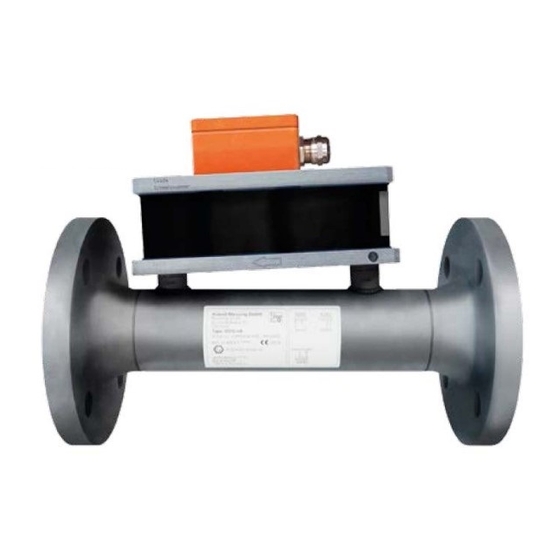
- Page 1 Operating Instructions Oscillation Flowmeter for dry and wet gases Model: DOG-… Sensor and Electronic Options A/B…O/P...
-
Page 2: Table Of Contents
reader/transducer ................13 Terminal assignment of the electronic option G0/H0/I0/K0/L0/M0/N0/O0/P0 ............15 Connections of DOG-… Transmitter with KOBOLD Evaluation Electronics ZED-X and ZOK-Zx ............17 Startup ......................20 Setup and operation of the flow controller/flow computer (option ... - Page 3 Manufactured and sold by: Kobold Messring GmbH Nordring 22-24 D-65719 Hofheim Tel.: +49(0)6192-2990 Fax: +49(0)6192-23398 E-Mail: info.de@kobold.com Internet: www.kobold.com DOG K11/0422 page 3...
-
Page 4: Note
Please read these operating instructions before unpacking and putting the unit into operation. Follow the instructions precisely as described herein. The instruction manuals on our website www.kobold.com are always for currently manufactured version of our products. Due to technical changes, the instruction manuals available online may not always correspond to the product version you have purchased. -
Page 5: Information On Operating The Device In Potentially Explosive Environments (Ex, A0/D0/F0/H0/K0/N0/P0 Option)
3. Information on operating the device in potentially explosive environments (Ex, A0/D0/F0/H0/K0/N0/P0 option) The devices can be used in the following way: Sensor DOG-…: In zones 0, 1 and 2 (gas Ex, category 1G, 2G, 3G) in explosion groups IIA, IIB and IIC Transmitter DOG-…: Outside the EX-area Here the following ambient temperatures must be adhered to -20 °C ≤... -
Page 6: Startup, Installation
3.2 Startup, installation The devices are intended for installation in a higher-level system. The intervals for cleaning the operating resources (dust deposits) are specified depending on the degree of IP protection. It is extremely important to ensure that only devices with suitable ignition protection for the zones/categories are installed! It is essential that the installation regulations applicable at the national level, e.g. -
Page 7: Repair, Maintenance (For Applications In Ex Areas)
3.4 Repair, maintenance (for applications in Ex areas) Definition of terms as defined in IEC 60079-17: Repair and maintenance: A combination of all activities carried out to maintain an item or restore the object to a state in which it is able to meet the requirements of the relevant specification and ensure the execution of its required functions. -
Page 8: Instrument Inspection
4. Instrument Inspection Instruments are inspected before shipping and sent out in perfect condition. Should damage to a device be visible, we recommend a thorough inspection of the delivery packaging. In case of damage, please inform your parcel service / forwarding agent immediately, since they are responsible for damages during transit. -
Page 9: Operating Principle
6. Operating Principle This device is an oscillating beam device and works without any movable parts. An orifice plate in the base creates flow resistance, which forces a partial flow to be directed into the oscillator. The gas in the oscillator begins to oscillate. The frequency of oscillation is proportional to the flow of volume. -
Page 10: Mechanical Connection
7. Mechanical Connection The measuring sensor should be installed in a horizontal position with the oscillator facing upwards. A slight inclination in the direction of flow is permitted. The arrow on the flange housing must point in the direction of flow. The recommended minimum inlet path is 10 times the diameter of the pipe and the maximum outflow zone 5 times the diameter of the pipe. -
Page 11: Identification (Ex Version)
8. Identification (Ex version) Type plate sensor DOG-… (flange housing, measurement tube) There is a warning label on the plastic housing “WARNING – DANGER Of ELECTROSTATIC DISCHARGE – SEE OPERATING INSTRUCTIONS” Type plate transmitter DOG-… (see left) DOG K11/0422 page 11... -
Page 12: Electrical Connections
9. Electrical connections General Install the measuring sensor near the transducer (max. 100 m cable length, depending on the electrical interference zone). The measuring cable must be laid well away from strong sources of electrical interference and not parallel to power cables. ... -
Page 13: Terminal Assignment Of The Dog
Terminal assignment of the DOG-… A/B/C/D/E/R… reader/transducer Output 230 V Sensor 110 V 24 V 24 V Supply Output Sensor black orange blue for AC for DC L = 230 V/110 V/24 V outer conductor + = supply DC+ N= 230 V/110 V/24 V neutral conductor - = supply DC- E = emitter optical coupler C = collector optical coupler... - Page 14 < 0.5 V HIGH R+4.4 kΩ Example: Vs = 24 V =17 V @ R=10 kOhm, U =23 V @R=80 kOhm, HIGH HIGH Optical coupler output, external supply max. 30 V = 50 mA page 14 DOG K11/0422...
-
Page 15: Terminal Assignment Of The Electronic Option
Terminal assignment of the electronic option G0/H0/I0/K0/L0/M0/N0/O0/P0 With the electronic option G0/H0/L0/M0/N0, the transmitter is located together with the flow controller/flow computer prewired in the plastic wall housing. The connection terminal strip is located underneath the terminal cover. This must be removed for the electrical connection. - Page 16 Wiring diagram electronic option G0/H0/I0/K0 Power Supply Analog Pulse XX VAC Output Output (10) (11) (12) max. 50mA 4-20mA Communication Optional Input Optional Input Flow Input RS485 (intrinsic safe) (intrinsic safe) (intrinsic safe) (17) (18) (19) (20) (21) (22) (13) (14) (15) (16)
-
Page 17: Connections Of Dog
Connections of DOG-… Transmitter with KOBOLD Evaluation Electronics ZED-X and ZOK-Zx 1,2 kOhm DOG-… connection with ZED-Zx DOG K11/0422 page 17... - Page 18 DOG-… connection with ZOK-ZxP Notes: * The sensor supply from ZOK-ZxP must be set to 8 VDC. From the software menu of ZOK-Zx, the ‘Sensor type’ must be set to ‘PNP’ (For details, please see the operating manual of ZOK-Zx electronics). page 18 DOG K11/0422...
- Page 19 Connection example for DOG-… with ZOK-ZxK The sensor type must be set to "PNP" in the ZOK-ZX software menu (see operating manual ZOK-Zx electronics). DOG K11/0422 page 19...
-
Page 20: Startup
10. Startup During startup, ensure that the shut-off valves upstream and downstream of the device are opened slowly. Avoid increasing the flow velocity to prevent the discharge rate from damaging the sensor. The output frequency of the DOG-... with the electronic options A/B/C/D/E/F/R is proportional to the measuring range. -
Page 21: Transmitter Error Message
12. Transmitter error message 12.1 Status display not illuminated Check terminal “230 V ” of the terminal assignment. Check supply voltage 12.2 OPERATING illuminated green but no output signal Check terminal “Output” of the terminal assignment 12.3 RANGE illuminated yellow ... -
Page 22: Maintenance
13. Maintenance 13.1 Replacing the sensor To replace the hot wire sensor, turn off the flow of medium and discharge the pressure in the lines. For versions with ball 1) 4x – 1.2-1.5 Nm valves, it is sufficient to simply shut these. Demounting (see diagram) is carried out in 4) 2x –... - Page 23 Do not use any sharp objects or Flow channel top aggressive cleaning agents. These could damage the oscillator, causing measurement inaccuracies breakdown of the device. Check the inflow and discharge channel and clean if necessary. Reassembly takes place in the reverse order.
-
Page 24: Technical Data
14. Technical Data 1,5% of reading (at Q Measuring accuracy: ≤MW≤100%*) 5% of reading (at 1%≤MW≤-Q *The lower limit Q depends on the density. = 8% at density 1 kg/m³ = 4% at density 2 kg/m³ = 2% at density 4 kg/m³ = 1% at density ... -
Page 25: Electronic Options
14.1 Electronic options Electronics DOG-…A0/B0 (Sensor with/without ATEX/IECEx certification) Power supply A/B: 230 V ± 10 %, 50…60 Hz Power supply C/D: 110 V ± 10 %, 50…60 Hz Power supply E/F: 24 V ± 10 %, 50…60 Hz Power supply R: 24 V ±... - Page 26 Electronics DOG-…G/H/I/K/L (Sensor without/with ATEX/IECEx certification and Flow rate/Unit counter, with current/pulse output) Display: alphanumeric LCD, UV-resistant, with displayed functions: Compensated flow rate (7 digits, 17 mm high) Compensated total (7 digits, 17 mm high) resettable Accumulated total (11 digits, 8 mm high) not resettable Units: Flow: m...
- Page 27 Electronic Options DOG-…M/N/O/P (Sensor without/with ATEX/IECEx certification and Flow computer) Display: Alphanumeric LCD, UV-resistant with Displayed functions: Compensated Flow rate (7 digits, 17 mm high) Compensated total: (7 digits, 17 mm high) resettable Accumulated total (11 digits, 8 mm high) not resettable Actual line temperature (6 digits) Actual line pressure (6 digits)
- Page 28 Display Note: Temperature and pressure sensors are not included in scope of delivery. page 28 DOG K11/0422...
-
Page 29: Order Details
15. Order Details DOG K11/0422 page 29... - Page 30 page 30 DOG K11/0422...
- Page 31 DOG K11/0422 page 31...
- Page 32 page 32 DOG K11/0422...
- Page 33 DOG K11/0422 page 33...
- Page 34 Order Details/Spare parts for DOG-4/-6 Order code Description Image DOG-4SEN221018 DOG-4 spare sensor with transport sleeve, 10 mm plate DOG-4SEN221016 DOG-4 spare sensor with transport sleeve, 15 mm plate DOG-6SEN221195 DOG-6 spare sensor with transport sleeve DOG-4/-6 calibration software with PC interface with USB DOG-4KAL01 connection DOG-DICH221196...
-
Page 35: Pressure Loss/Flow
16. Pressure Loss/Flow Pressure drop [mbar] The diagram applies for gases with a density of air at NPT (0 °C and 1013.25 mbar). The pressure loss is always proportional to the density of the gas. For example, at 100% higher density there is double pressure loss. ... -
Page 36: Dimensions
17. Dimensions Dimensions and Weights DOG-4/-6 (without ball valve) page 36 DOG K11/0422... - Page 37 Dimensions and Weights DOG-4/-6 (with ball valve) DOG K11/0422 page 37...
- Page 38 Dimensions Electronics DOG-…A/B/C/D/E/F/R Dimensions Electronics DOG-…G/H/I/K/L/M/N/O page 38 DOG K11/0422...
-
Page 39: Eu Declaration Of Conformance
18. EU Declaration of Conformance We, KOBOLD Messring GmbH, Hofheim-Ts, Germany, declare under our sole responsibility that the product: Oscillation Flowmeter Model: DOG-4/-6 to which this declaration relates is in conformity with the standards noted below: EN 61326:2013-07 Electrical equipment for measurement, control and laboratory... - Page 40 additional for DOG-4/-6…A/H/N/D/F/P/K: 2014/34/EU Equipment and Protective systems intended for use in a potentially Explosive Atmospheres Quality Management Production Certificate number: BVS 21 ATEX ZQS/E110 Notified body: DEKRA Testing and Certification GmbH Identification number: 0158 Hofheim, 14 April 2022 H. Volz M.
-
Page 41: Atex-Certificate
19. ATEX-Certificate DOG K11/0422 page 41... - Page 42 page 42 DOG K11/0422...
- Page 43 DOG K11/0422 page 43...
- Page 44 page 44 DOG K11/0422...
- Page 45 DOG K11/0422 page 45...
- Page 46 page 46 DOG K11/0422...
- Page 47 DOG K11/0422 page 47...
- Page 48 page 48 DOG K11/0422...
- Page 49 DOG K11/0422 page 49...
-
Page 50: Iecex-Certificate
20. IECEx-Certificate page 50 DOG K11/0422... - Page 51 DOG K11/0422 page 51...
- Page 52 page 52 DOG K11/0422...
- Page 53 DOG K11/0422 page 53...
- Page 54 page 54 DOG K11/0422...
- Page 55 DOG K11/0422 page 55...
- Page 56 page 56 DOG K11/0422...
- Page 57 DOG K11/0422 page 57...
- Page 58 page 58 DOG K11/0422...
Need help?
Do you have a question about the DOG Series and is the answer not in the manual?
Questions and answers