Table of Contents
Advertisement
Quick Links
Advertisement
Table of Contents

Related Manuals for Kobold DSS Series


Summary of Contents for Kobold DSS Series
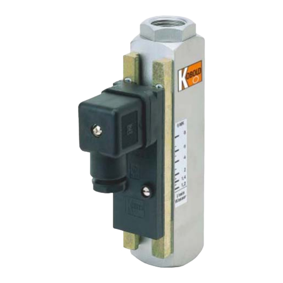
- Page 1 Operating Instruction Flow Monitor Model: DSS-...
-
Page 2: Table Of Contents
EC-Type Examination Certificate Magnetic reed switch (F0) ...... 28 IECEx certificate (F0) .................. 31 Manufactured and sold by: Kobold Messring GmbH Nordring 22-24 D-65719 Hofheim Tel.: +49(0)6192-2990 Fax: +49(0)6192-23398 E-Mail: info.de@kobold.com Internet: www.kobold.com Page 2... -
Page 3: Note
Please read these operating instructions before unpacking and putting the unit into operation. Follow the instructions precisely as described herein. The instruction manuals on our website www.kobold.com are always for currently manufactured version of our products. Due to technical changes, the instruction manuals available online may not always correspond to the product version you have purchased. -
Page 4: Regulation Use
4. Regulation Use Model DSS instruments monitor liquid flows. Only clean, homogeneous liquids of low viscosity - against which the instrument materials are resistant - should be monitored. Large switching inaccuracies may occur with highly viscous media. Large dirt particles can block the float and thus cause faulty signals. Pieces of ferrite deposited on the embedded float magnet can also cause problems. -
Page 5: Mechanical Connection
6. Mechanical Connection Before installation Make sure that the max. allowed operating pressures and service temperatures are not exceeded (see standard material combinations). The instrument is fitted vertically in the piping. Flow is from bottom to top (vertical dial). -
Page 6: Ex-Contact With Cable Connection
7.2. Ex-Contact with Cable Connection Special conditions for a safe application The connection of the solenoid switch must be carried out in housings which correspond to a standardized ignition protection class in accordance with EN 50014, 1.2. The short-circuit current I of the supply source must not exceed 5 A. -
Page 7: Use In Hazardous Area
8. Use in hazardous area 8.1. Statement an apparatus not containing an own potential source following Directive 2014/34/EU DSS K08/0322 Page 7... -
Page 8: Atex Contact
8.2. ATEX contact ...F0... II 2G Ex mb IIC T6 Gb II 2 D Ex mb IIC T80 °C Db max. 250 V /1.5 A/100 VA 8.3. ATEX reed contact 41R57** ATEX N/O contact 41R57 II 3G Ex ic IIC T4 Gc II 3 D Ex ic IIIC T125 °C Dc -20 °C ≤Ta≤80 °C max. - Page 9 To ensure the function and for your own safety, please read the enclosed operating instructions carefully before you begin the installation. If you have any questions, please contact the KOBOLD Messring GmbH, Hofheim. It applies with the original operating instructions.
- Page 10 2.1. Electrical characteristics for Ex i Electrical data: • Rated voltage up to 45 volt AC / DC • Rated current up to 2 A • Ui ≤ 30 V AC / DC, Ii ≤ 250 mA • Ui ≤ 45 V AC / DC, Ii ≤...
- Page 11 2.4.2 General safety instructions The reed switch corresponds to the state of the art and is reliable. The reed switch may pose a residual hazard if improperly used and operated by untrained personnel. Every person responsible for the installation, commissioning, maintenance or repairing of the reed switch must have read and understood the assembly instructions and in particular the safety instructions.
- Page 12 f) Heat radiation from foreign products / components must also be considered. g) The reed switch must be protected against inadmissible access of liquids and / or soiling. h) Fixed parts (e.g. due to frost or corrosion) must not be loosened by force in the presence of an explosive atmosphere.
- Page 13 4. Maintenance, servicing Definition of terms according to IEC 60079-17: Maintenance and Repair: A combination of all activities performed to maintain or recover an item in a condition that meets the requirements of the specification in question and ensures the performance of the required functions. Inspection: An activity involving the careful examination of an object, with the aim of obtaining a reliable statement of the condition of the object, carried out without disassembly or, if necessary, with partial disassembly, supplemented by...
- Page 14 Close detailed visual inspection inspection Activity inspection per every every month 6 months 12 months Visual inspection of the reed switch for damage, remove ● dust deposits Check for integrity and ● function Testing the entire system The responsibility of the operator 5.
-
Page 15: Commissioning
9. Commissioning When used in machines according to guideline 89/392/EWG commissioning is prohibited until it is established that the machine meets the general requirements of the guideline. Setting limit values Loosen both retaining screws at the contact stem with a screwdriver. ... -
Page 16: Technical Information
11. Technical Information Housing: DSS-11.. : brass, Ms 58 DSS-12.. : st. st., 1.4301 Connections: DSS-11.. : brass, Ms 58 DSS-12.. : st. st., 1.4301 Float: DSS-11.. : brass, Ms 58 DSS-1101: PP DSS-12.. : st. st., 1.4301 DSS-1201: PVDF Nozzle: DSS-11.. - Page 17 Electrical contacts ATEX contact …F0: II 2 G Ex mb IIC T6 Gb II 2 D Ex mb IIC T80 °C Db max. 250 V /1.5 A/100 VA ATEX N/O contact type 41T57 …G0 and GG: II 3 G Ex ic IIC T4 Gc II 3 D Ex mb IIIC T125 °C Dc -20 °C ≤...
-
Page 18: Order Codes
12. Order Codes Example: (DSS-1101H R0 R08) Measuring Brass Stainless Contact* Connection range l/min. steel water 0.05...1 DSS-1101H... DSS-1201H..R0.. = 1 N/O contact ..U0.. = 1 changeover contact 0.15...1.7 DSS-1103H... DSS-1203H..F0.. = 1 EX N/O contact 1...4.5 DSS-1105H... DSS-1205H... -
Page 19: Recommended Spare Parts
Ex contact for DSS-..F0.. 14. Recommended Spare Parts Only device parts and materials are listed. Parts are supplied in different sizes to suit the instrument models. (Specify instrument model when placing order). 1.1) Float brass 3.2) O ring set FPM 1.2) Float polypropylene 4.1) Contact (N/O function) 1.3) Float stainless steel... -
Page 20: Eu Declaration Of Conformance (Dss)
15. EU Declaration of Conformance (DSS) We, KOBOLD-Messring GmbH, Hofheim-Ts, Germany, declare under our sole responsibility that the product: Flow Monitor Model: DSS-... to which this declaration relates is in conformity with the standards noted below: EN 61010-1:2011 Safety requirements for electrical equipment for measurement, control and... -
Page 21: Declaration Of Conformity (Dss)
ATEX not available in GB 16. UK Declaration of Conformity (DSS) We, KOBOLD Messring GmbH, Hofheim-Ts, Germany, declare under our sole responsibility that the product: Flow Monitor Model: DSS-... to which this declaration relates is in conformity with the standards noted below:... -
Page 22: Eu Declaration Of Conformance (Reed Contact 41R57**)
ATEX not available in GB 17. EU Declaration of Conformance (reed contact 41R57**) Page 22 DSS K08/0322... -
Page 23: Statement Of Conformity Reed Contact 41R57
ATEX not available in GB 18. Statement of conformity reed contact 41R57** DSS K08/0322 Page 23... - Page 24 ATEX not available in GB Page 24 DSS K08/0322...
- Page 25 ATEX not available in GB DSS K08/0322 Page 25...
- Page 26 ATEX not available in GB Page 26 DSS K08/0322...
-
Page 27: Declaration Of The Manufacturer (F0)
ATEX not available in GB 19. Declaration of the Manufacturer (F0) DSS K08/0322 Page 27... -
Page 28: Ec-Type Examination Certificate Magnetic Reed Switch (F0)
ATEX not available in GB 20. EC-Type Examination Certificate Magnetic reed switch (F0) Page 28 DSS K08/0322... - Page 29 ATEX not available in GB DSS K08/0322 Page 29...
- Page 30 ATEX not available in GB Page 30 DSS K08/0322...
-
Page 31: Iecex Certificate (F0)
ATEX not available in GB 21. IECEx certificate (F0) DSS K08/0322 Page 31... - Page 32 ATEX not available in GB Page 32 DSS K08/0322...
- Page 33 ATEX not available in GB DSS K08/0322 Page 33...
- Page 34 ATEX not available in GB Page 34 DSS K08/0322...
- Page 35 ATEX not available in GB DSS K08/0322 Page 35...
- Page 36 ATEX not available in GB Page 36 DSS K08/0322...
Need help?
Do you have a question about the DSS Series and is the answer not in the manual?
Questions and answers