Table of Contents
Advertisement
Quick Links
Advertisement
Table of Contents

Related Manuals for Dnake IPK05


Summary of Contents for Dnake IPK05
- Page 1 User Manual ——— DNAKE IPK05...
- Page 3 REMARK Please follow the user manual for correct installation and testing. If there is any doubt please call our tech-supporting and customer center. Our company applies ourselves to reformation and innovation of our products. No extra notice for any change. The illustration shown here is only for reference. If there is any difference, please take the actual product as the standard.
-
Page 5: Table Of Contents
CATALOG PRODUCT FEATURE ..........1 TECHNICAL PARAMETER ........1 PACKAGE CONTENT ..........3 OVERVIEW ..............4 BASIC OPERATION ..........5 SYSTEM DIAGRAM ..........23 DEVICE WIRING ...........24 INSTALLATION .............28 TROUBLESHOOTING ...........35 SAFETY INSTRUCTION ........36 FCC WARNING .............37... -
Page 7: Product Feature
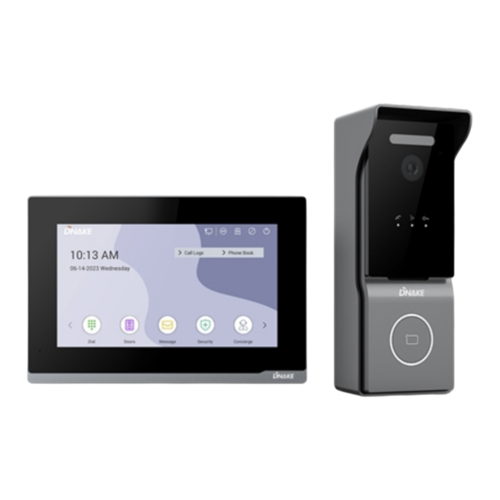
PRODUCT FEATURE 1. Plug & Play 2. Motion detection 3. Standard POE 4. One-touch calling 5. Remote unlocking 6. CCTV integration 7. 2MP HD digital WDR camera TECHNICAL PARAMETER Indoor Monitor E217W Power Supply: POE (802.3af) or DC 12V/2A Standby Power: 1.5 W Rated Power: 9 W Display: 7-inch TFT LCD Screen: Capacitive touchscreen... -
Page 8: Package Content
PACKAGE CONTENT MODEL: IPK05 E217W Wiring Cover PM4×20 (2 pcs) Diode (3 pcs) C112A Screw Fixing Seat Sealing Plug of Rear Cover PA4×25 (3 pcs) Rain Hood (3 pcs) Wiring Port Wrench Screw Junction Pressing PM2×6 (2 pcs) FM3×6 (1 pcs) FM3×6 (1 pcs) -
Page 9: Overview
OVERVIEW Note: Calling indicator light: The 1st indicator light will activate if the call button is pressed. Talking indicator light: The 2nd indicator light will activate if the call is picked up or the Villa station is being actively monitored. Unlocking indicator light: The 3rd indicator light activates for 3 seconds when the door is unlocked. -
Page 10: Basic Operation
BASIC OPERATION 1. Onboarding 1.1. Language Language is the first setting. We have 16 kinds of languages (Chinese Simplified, Chinese Traditional, English, Spanish, German, Polish, Russian, Turkish, Hebrew, Arabic, Portuguese, French, Italian, Slovak, Vietnamese, and Dutch) for customers to choose from. Click Next to move on. 1.2. - Page 11 Wi-Fi function and scan the list of available networks to locate the door station's AP hotspot. 2. Enable and select the Wi-Fi “IPK05-C112A-XXXX”,locate the door station's AP hotspot and connect to it.
- Page 12 1.5. Wired network configuration On this page, users can click “Skip” to configure the indoor unit's wired network settings, including the option to enable or disable DHCP. Note:Users can choose either a wired network or a wireless network, but not both simultaneously.
- Page 13 It's coming to an end here. All the basic settings are done. 1.7. Scan with DNAKE Smart Life APP Click the QR Code icon on the upper left corner. Download DNAKE Smart Life APP and Scan QR code. User should register an account and log in with email address.
- Page 14 2. Call Indoor Monitor by Villa station 1. Press the Button on Villa station to make this call. You can answer, reject, open the door, or speak with the visitor. 3. Monitor Villa station on Indoor Monitor 1. Press Doors on Indoor Monitor to monitor Villa station. If you have two Villa stations connecting to Indoor Monitor, you need to switch devices above.
- Page 15 1. Enter default IP 192.168.68.89 to browse villa station’s webpage and go to person page. 2. Click Add to add cards. After clicking the Read icon, tap the card on villa station to read. Remember to save the settings. 5. IP Camera Monitoring 5.1.
- Page 16 2. Add IP Camera to the Indoor Monitor on the website: 1. Enter default IP 192.168.68.90 to browse indoor monitor’s webpage and go to IPC page to fill in RTSP of IP camera. Please get your IPC RTSP stream URL from IPC manufacturer.
- Page 17 in the browser's search bar to log in its webpage with account: admin and password:123456 Step 2: Go to Advanced > Video to select RTSP Feed and type in URL. URL contains account, password, and IP address. Make sure URL of the IP Camera is right.
- Page 18 Step 4: Click the little Keyboard icon to fold the keyboard panel so that you can see the whole monitoring screen. 6. Add Villa station to Resident's Phone 6.1. Download Smart Life app Resident can also download the Smart Life app by searching for Smart Life in app store, Google Play Store or by scanning the following QR code.
- Page 19 2. Enter resident's email address and tap Get Verification Code. The country or region on the registration page is the same as that resident set in the mobile phone. Resident can also manually change the country or region before registration. 3.
- Page 20 Step 2: Click QR code in the upper right corner. Step 3: Scan QR code. One QR code can only be bound to one phone but resident can share resident's authority to its family members up to 20 users. 2. Congratulations. Villa station is successfully connected to resident's phone. 3.
- Page 21 answer the call and unlock remotely. Smart Life App can also monitor and unlock Villa station. 6.4. Rename devices 1. After scanning the device, resident will see the reminder (Added successfully). In this page, resident can edit the name and room of this device. 2.
- Page 22 6.5. Share devices 1. Resident can create a home to share resident's devices in this group. The following steps and pictures are here for reference. Step 1: Go to Me page and then open Home Management. Step 2: Select My Home or Create a Home. Step 3: In the Home Setting page, resident can rename, locate, or share resident's device.
- Page 23 7. Add Subordinate Indoor Monitor 7.1. Add subordinate Indoor Monitor 1. After having added first Indoor Monitor successfully, resident can add more subordinate Indoor Monitors to it. The maximum amount of Indoor Monitor is six. Step 1: Connect subordinate Indoor Monitor to the same LAN. Step 2: Follow the guide on it.
- Page 24 Step 5: As shown in the image, you need to set up the network to find the main indoor monitor. If the main indoor monitor uses Wi-Fi, turn on the Wi-Fi option and ensure that both the subordinate and main indoor monitors are connected to the same Wi-Fi network.
- Page 25 Step 7: Once the main device is found, select the corresponding MAC address to complete the pairing process. Note:If the main device is not found, the screen will display "Not found First Monitor."You can either re-initiate the search or return to the previous step to reconfigure the network settings.
- Page 26 Step 8: It's coming to an end here. All the basic settings are done.
-
Page 27: System Diagram
SYSTEM DIAGRAM... -
Page 28: Device Wiring
DEVICE WIRING E217W 1. Network (PoE) Standard RJ45 interface is for the connection with PoE switch or other network switch. PSE shall comply with IEEE 802.3af (PoE) and its output power not less than 15.4W and its output voltage not be less than 50V. 2. - Page 29 Warning! 1. When connecting to an inductive load device such as a relay or electromagnetic lock, you are recommended to use a diode 1A/400V (included in the accessories) in anti- parallel with the load device to absorb inductive load voltage peaks.
- Page 30 C112A 1. Network (PoE) / RJ45 (Non-standard PoE) Standard RJ45 interface is for the connection with PoE switch or other network switch. PSE shall comply with IEEE 802.3af (PoE) and its output power not less than 15.4W and its output voltage not be less than 50V. 2.
- Page 31 Warning! 1. When connecting to an inductive load device such as a relay or electromagnetic lock, you are recommended to use a diode 1A/400V (included in the accessories) in anti- parallel with the load device to absorb inductive load voltage peaks.
-
Page 32: Installation
INSTALLATION Surface Mounting-86 Mounting Box Product size: 195 × 130 × 14.5 mm... - Page 33 Installation of Rain Hood 1. Choose the suitable height of camera, and put the label sticker on the wall. 2. According to the sticker, drill three 8 x 45mm for screws and one 5mm for wire outlet. 3. Insert 3 screw fixing seats into the screw holes. 4.
- Page 34 9. Plug waterproof seal plug into the cover groove at the bottom. 10. Fix interface clamp to the device with 2 screws.
- Page 35 11. Hang up device with rain hood. 12. Use wrench to lock the bottom of the device with 1 screw (different screws for rain hood and rear cover).
- Page 36 Installation of Rear Cover 1. Choose the suitable height of camera, and put the label sticker on the wall. 2. According to the sticker, drill three 8 x 45mm for screws and one 5mm for wire outlet. 3. Insert 3 screw fixing seats into the screw holes. 4.
- Page 37 9. Plug waterproof seal plug into the cover groove at the bottom. 10. Fix interface clamp to the device with 2 screws.
- Page 38 11. Hang up device with rear cover. 12. Use wrench to lock the bottom of the device with 1 screw (different screws for rain hood and rear cover). Tips: The camera should be 1450~1550mm above the ground. The camera at this height can capture human face perfectly.
-
Page 39: Troubleshooting
TROUBLESHOOTING The Indoor Monitor cannot start up or power off automatically. Check whether it has power-failure, and power it on again The Indoor Monitor display screen is too dim. Check whether the brightness and contrast settings of screen are correct. No sound during the communication. -
Page 40: Safety Instruction
SAFETY INSTRUCTION In order to protect you and others from harm or your device from damage, please read the following information before using the device. Do not install the device in the following places: Do not install the device in high-temperature and moist environment or the area close to magnetic field, such as the electric generator, transformer or magnet. -
Page 41: Fcc Warning
FCC WARNING This device complies with Part 15 of the FCC Rules. Operation is subject to the following two conditions: (1) This device may not cause harmful interference, and (2) this device must accept any interference received, including interference that may cause undesired operation. - Page 42 RF exposure statement This equipment complies with the FCC radiation exposure limits set forth for an uncontrolled environment. This transmitter must not be co-located or operating in conjunction with any other antenna or transmitter.
- Page 44 V1.0 600110165300 EASY & SMART INTERCOM SOLUTIONS...
Need help?
Do you have a question about the IPK05 and is the answer not in the manual?
Questions and answers