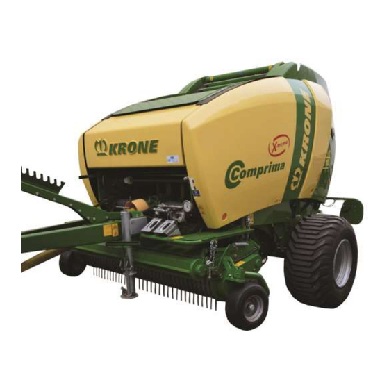
Krone Comprima F 155 XC X-treme Original Operating Instructions
Hide thumbs
Also See for Comprima F 155 XC X-treme:
- Original operating instructions (278 pages) ,
- Original operating manual (234 pages) ,
- Original operating instructions (366 pages)

Related Manuals for Krone Comprima F 155 XC X-treme


Summary of Contents for Krone Comprima F 155 XC X-treme
- Page 1 Round baler Comprima F 155 XC X-treme Comprima V 150 XC X-treme (from serial no.: 976 393) Order no.: 150 000 165 07 en 01.02.2018...
- Page 2 Machine: Round Baler Type: Comprima F 155 XC X-treme Comprima V 150 XC X-treme to which this declaration refers is in compliance with the following relevant provisions of: • EC Directive 2006/42/CE (machines), •...
-
Page 3: Table Of Contents
Table of Contents Table of Contents Table of Contents ........................... 3 To this Document ..........................10 Validity .............................. 10 Re-Ordering ............................10 Further applicable documents ......................10 Target group of this document ......................10 How to use this document ........................ 10 2.5.1 Directories and References ...................... - Page 4 Hydraulic brake (Export) ........................94 Hydraulic brake (auxiliary brake) ...................... 94 Install the PTO shaft ......................... 95 Compressed Air Connections for the Compressed Air Brake ............97 Connecting KRONE BETA II Terminal ..................... 98 Connecting KRONE ISOBUS-Terminal ..................100 Connecting External ISOBUS-Terminal ..................103...
- Page 5 General Information on ISOBUS ....................127 11.2 ISOBUS Shortcut Button not Available ..................128 11.3 Deviating Functions from KRONE ISOBUS Terminal ..............128 Terminal – Machine Functions ......................129 12.1 General Information on Functioning of Machine and Terminal ............129 12.2...
- Page 6 Table of Contents 13.6.5 Menu 4 “Tying Start Delay” (net tying) ..................152 13.6.6 Menu 4 “Tying Start Delay” (film tying) ................... 153 13.6.7 Menu 5 “Bale Diameter” (Comprima F) ................... 154 13.6.8 Menu 6 “Electronical Baling Pressure Adjustment” (Comprima V) ......... 155 13.6.9 Menu 7 “Sensitivity of Direction Display””...
- Page 7 Table of Contents 15.3.2 Mounting additional driver guide rails on the starter roller ............205 15.3.3 Removing the Sliding Plates ....................206 15.3.4 Mounting additional deflector sheets in the tailgate ..............206 15.4 Wrapping and Depositing Bales ..................... 207 15.5 Driving with Bale Ejector ........................
- Page 8 Setting Sensor B3 Net Motor Position ..................274 17.7.3 Setting Sensor B8 Position Blade Cassette ................276 17.7.4 Adjusting sensor B9/B10 baling pressure (Comprima F 155 XC X-treme) ......277 17.7.5 Adjusting sensor B9/B10 bale diameter (Comprima V 150 XC X-treme) ....... 278 17.7.6 Setting Sensor B14/B15 Bale Chamber Opened/Bale Ejection (for “TIM”...
- Page 9 Malfunctions on Job Computer ...................... 329 20.4 Faults in case of TIM (Tractor Implement Management) ............... 330 20.5 Error Messages of KRONE Operation Terminal ................330 Placing in Storage ..........................331 21.1 At the End of the Harvest Season ....................331 21.2...
-
Page 10: To This Document
If this document has become unusable in whole or in part, you can order a replacement, quoting the document number on the cover sheet. Contact data can be found in the chapter “Contact persons”. The document can additionally be downloaded via the KRONE Media Center http://www.mediathek.krone.de//. Further applicable documents... -
Page 11: Direction Information
To this Document 2.5.2 Direction Information Direction information in this document such as front, rear, right and left always applies in the direction of travel. Term “Machine” 2.5.3 Throughout the rest of this document, the “round baler” will also be referred to as the “machine”. 2.5.4 Figures The figures in this document do not always represent the exact machine type. - Page 12 To this Document Symbols in figures To visualize parts and actions steps, the following icons are used: Icon Explanation Reference sign for part Position of a part (e.g. move from pos. I to pos. II) Dimensions (e.g. B = width, H = height, L = length) Action step: Tighten screws with torque key with specified tightening torque Direction of motion Direction of travel...
- Page 13 To this Document Warning signs Warning WARNING! - Type and source of hazard! Effect: Injuries, serious material damage. • Measures for hazard prevention. Caution CAUTION! - Type and source of hazard! Effect: Damage to property. • Measures for risk prevention. Notes with information and recommendations Note Note...
-
Page 14: Conversion Table
To this Document 2.5.7 Conversion table By means of the following table, metric units can be converted into US units. Quantity SI Units (Metric) Factor Inch-Pound Units Unit Name Abbreviation Unit Name Abbreviation Area hectare 2.47105 acre acres Flow liters per L/min 0.2642 US gallon per... -
Page 15: Safety
Safety Safety Purpose of Use The round baler Comprima is a pick-up baler with variable bale chamber. It compacts agricultural material, such as hay, straw or grass silage into round bales. The round baler Comprima is equipped as standard with a net wrapping mechanism. WARNING! –... -
Page 16: Basic Safety Instructions
Safety Basic safety instructions Non-compliance with the safety instructions and warnings Non-compliance with the safety instructions and warnings may result in injuries and damage to the environment and property. 3.4.1 Importance of the operating instructions The operating instructions are an important document and a part of the machine. They are aimed at the user and contain safety-relevant information. -
Page 17: Children In Danger
Safety 3.4.4 Children in danger Children cannot assess danger and behave unpredictably. As a result, children are especially at risk. • Keep children away from the machine. • Keep children away from consumables. • Especially before starting up and moving the machine, ensure that there are no children in the danger zone. -
Page 18: Operational Safety: Technically Perfect Condition
Safety 3.4.9 Operational safety: Technically perfect condition Operation only when the machine has been started up correctly If the machine is not started up correctly according to these operating instructions, the operational safety of the machine is not ensured. As a result, accidents may occur and people may be seriously injured or killed. - Page 19 Safety Technical limit values If the technical limit values of the machine are not observed, the machine may be damaged. As a result, accidents may occur and people may be seriously injured or killed. Observance of the following technical limit values is particularly important for safety: –...
-
Page 20: Danger Zones
Safety 3.4.10 Danger zones When the machine is switched on, a danger zone may be created around this machine. To avoid getting into the danger zone of the machine, maintain at least the safety distance. If the safety distance is not followed, people may be seriously injured or killed. •... - Page 21 Safety Danger zone PTO shaft People may be caught, pulled in and seriously injured by the PTO shaft and the driven components. Before switching on the PTO shaft: • Make sure that all safety devices are fitted and in the protection position. •...
-
Page 22: Keeping Safety Devices Functional
Safety 3.4.11 Keeping safety devices functional If safety devices are missing or damaged, people may be seriously injured or killed by moving machine parts. • Replace damaged safety devices. • Remount dismounted safety devices and all other parts before start-up and move them to protective position. -
Page 23: Safety Signs On The Machine
Safety 3.4.13 Safety signs on the machine Safety stickers on the machine warn of hazards in danger areas and are an important component of the safety equipment of the machine. Missing safety stickers increase the risk of serious and fatal injuries. •... -
Page 24: Parking The Machine Safely
Safety 3.4.15 Parking the machine safely An improperly parked machine can start to move in an uncontrolled manner or tip over. People may be crushed and killed. • Park the machine on a stable, horizontal and even surface. • Before adjusting, repairing, maintaining or cleaning the machine, ensure that it is securely positioned. - Page 25 Safety Behaviour in the case of voltage flashover of overhead lines High electric voltage may be applied to electrically conducting parts of the machine due to voltage flashover. In case of voltage flashover, a voltage drop where major voltage differences are present is created on the ground around the machine.
-
Page 26: Sources Of Danger On The Machine
Safety 3.4.18 Sources of danger on the machine Noise may damage your health The noise development of the machine during operation may cause health damage such as hardness of hearing, deafness or tinnitus. When using the machine at high rotational speed, the noise level also increases. -
Page 27: Dangers Associated With Certain Activities: Climbing Up And Down
Safety 3.4.19 Dangers associated with certain activities: Climbing up and down Climbing up and down safely People who behave carelessly when climbing up and down may fall off the ladder. People, who climb onto the machine without using the designated ladders, may slip, fall and seriously injure themselves. -
Page 28: Dangers Associated With Certain Activities: Working On Wheels And Tyres
The fitting of wheels and tyres requires adequate knowledge and approved tools. • If there is a lack of knowledge, have the wheels and tyres fitted by the KRONE dealer or by a qualified tyre service. •... -
Page 29: Safety Routines
Safety Safety routines 3.5.1 Stopping and securing the machine WARNING! Risk of injury due to movement of the machine or machine parts! If the machine has not been shut down, machine or machine parts may move unintentionally. People may be seriously injured or killed, as a result. •... -
Page 30: Safely Checking The Oil Level And Changing The Oil And Filter Element
Safety 3.5.3 Safely checking the oil level and changing the oil and filter element WARNING! Perform oil level check, oil change and filter element change safely! If oil level check, oil change and filter element change are not performed safely, the operational safety of the machine may be affected. -
Page 31: Safety Stickers On The Machine
Position and meaning of the safety stickers on the machine The KRONE round baler is equipped with all safety devices (protective equipment). However, it is not possible to eliminate all potential hazards on this machine as this would impair its full functional capability. - Page 32 Safety Comprima F 155 XC X-treme RPN00080_1 Fig. 1 RPN00081_1 Fig. 2...
- Page 33 Safety 1) Order no. 939 471 1 (2x) Danger due to incorrect operation and lack of knowledge Incorrect operation and lack of knowledge of the machine as well as incorrect behaviour in hazardous situations is risking the life of the operator and third parties. •...
- Page 34 Safety Comprima F 155 XC X-treme RPN00080_1 Fig. 3 RPN00081_1 Fig. 4...
- Page 35 Safety 5) Order No. 939 125 1 (2x) H = 100 mm Danger from sharp blades. There is a risk of cuts when reaching into the danger zone of the blades. • Wear cut-resistant gloves. 6) Order No. 27 014 371 0 (2x) Danger from shock and crush Danger to life due to sagging tailgate.
- Page 36 Safety Comprima F 155 XC X-treme RPN00080_1 Fig. 5 RPN00081_1 Fig. 6...
- Page 37 Safety 9) Order No. 942 360 4 (1x) Danger caused by unintended movement of the machine when opening the tailgate. Risk of injury due to rolling away or tilting machine. • Before opening the tailgate, make sure that the machine is correctly attached to the tractor.
- Page 38 Safety Comprima F 155 XC X-treme RPN00080_1 Fig. 7 RPN00081_1 Fig. 8...
- Page 39 Safety 13) Order No. 939 408 2 (2x) Danger from rotating machine parts. When getting on the machine while the PTO shaft is running, there is a danger of entanglement caused by rotating machine parts. • Switch off PTO shaft and engine before getting on the machine.
- Page 40 Safety Comprima V 150 XC X-treme HDC00081_1 Fig. 9 HDC00082_1 Fig. 10...
- Page 41 Safety 1) Order no. 939 471 1 (2x) Danger due to incorrect operation and lack of knowledge Incorrect operation and lack of knowledge of the machine as well as incorrect behaviour in hazardous situations is risking the life of the operator and third parties. •...
- Page 42 Safety Comprima V 150 XC X-treme HDC00081_1 Fig. 11 HDC00082_1 Fig. 12...
- Page 43 Safety 5) Order No. 27 014 371 0 (2x) Danger from shock and crush Danger to life due to sagging tailgate. • When doing maintenance work in the area of the tailgate, close the stop cock on the left lifting cylinder. •...
- Page 44 Safety Comprima V 150 XC X-treme HDC00081_1 Fig. 13 HDC00082_1 Fig. 14...
- Page 45 Safety 9) Order No. 942 360 4 (1x) Danger caused by unintended movement of the machine when opening the tailgate. Risk of injury due to rolling away or tilting machine. • Before opening the tailgate, make sure that the machine is correctly attached to the tractor.
- Page 46 Safety Comprima V 150 XC X-treme HDC00081_1 Fig. 15 HDC00082_1 Fig. 16...
- Page 47 Safety 13) Order No. 939 408 2 (2x) Danger from rotating machine parts. When getting on the machine while the PTO shaft is running, there is a danger of entanglement caused by rotating machine parts. • Switch off PTO shaft and engine before getting on the machine.
-
Page 48: Re-Ordering Safety Labels And Information Labels
Safety 3.6.2 Re-Ordering Safety Labels and Information Labels Note Each safety and information label is provided with an order number and can be ordered directly from the manufacturer or from authorised dealer (refer to chapter “Contact Person”). 3.6.3 Attaching Safety Labels and Information Labels Note - Attaching a label Effect: Adhesion of label •... -
Page 49: Contact
Safety 3.6.4 Contact Maschinenfabrik Bernard Krone GmbH & Co. KG Heinrich-Krone-Strasse 10 D-48480 Spelle (Germany) Telephone: + 49 (0) 59 77/935-0 (Head Office) Fax.: + 49 (0) 59 77/935-339 (Head Office) Fax.: + 49 (0) 59 77/935-239 (Spare parts - domestic) -
Page 50: Safety Equipment
Safety Safety Equipment WARNING! - Unexpected movement of components due to defective safety equipment! Effect: Danger to life, risk of a serious accident or damage to the machine • Machine must not be started without functioning safety equipment. 3.7.1 Parking Brake WARNING! Unexpected movement of the machine! The machine may move unintentionally if the parking brake is not activated when parking the... -
Page 51: Parking Support
Safety 3.7.2 Parking Support WARNING! Crushing hazard caused by parking support When actuating the parking support, hands or feet could be crushed. • Keep hands and feet away from danger zone of parking support. The parking support provides stability of the machine when it is not attached to the tractor. Use it whenever the machine is parked. - Page 52 Safety COM00447 Fig. 19 • To fold in the crank handle (1) from position [I] to position [II], pull out the spring cotter pin (5) on the crank handle (1). • Fold in the crank handle (1) in the direction of the arrow and secure position [II] by means of the spring cotter pin (5).
- Page 53 Safety On the crank handle (1), two positions can be selected to rotate the crank handle: Crank handle position Explanation The crank handle (1) is • To lower the parking support (2), turn the crank handle inserted. (1) counter-clockwise. • To lift the parking support (2), turn the crank handle (1) clockwise.
- Page 54 Safety For design with hydraulic support jack Moving parking support into transport position Prerequisite: – The machine is attached to the tractor. COM00409 Fig. 22 • Retract support jack (1) via tractor control unit. COM00410 Fig. 23 • Turn bolt (1) by 90° to the right so that the locking pin (2) is no longer locked. •...
- Page 55 Safety Moving parking support into support position Prerequisite: – The machine is attached to the tractor. COM00412 Fig. 24 • Loosen the bolt (1) from the locking spring (2) and turn it by 90° to the right so that the locking pin (3) is no longer locked.
-
Page 56: Wheel Chocks
Safety 3.7.3 Wheel chocks Fig. 26 The wheel chocks (1) are kept in a holder at the front left beside the drawbar. Each one is locked in position in the holder by a spring clip. KR-1-081 Fig. 27 • Park the machine on level and firm ground. •... -
Page 57: Stop Points
Safety 3.7.4 Stop Points WARNING! Danger from falling loads! • Never step or stay under suspended loads! • Maintain an adequate safety distance from suspended loads. • Before transportation, compare load capacity of slings and cranes and choose transportation equipment with a sufficient degree of safety and lifting capacity. •... -
Page 58: Shut-Off Valve For Tailgate
Safety 3.7.5 Shut-off valve for tailgate WARNING! – Settings on the machine! Danger to life or serious injuries. • The shut-off valve on the left hydraulic cylinder must be closed. CPK00230_3 Fig. 28 The tractor supplies pressure to the machine hydraulics via hoses. In addition to different parts, the shut-off valve (1) on the left hydraulic cylinder should particularly be mentioned. -
Page 59: Smv Emblem
Safety 3.7.6 SMV Emblem For version with “SMV emblem” Fig. 29 The SMV emblem (Slow-Moving Vehicle) (1) can be mounted on slowly moving machines or vehicles. The country-specific specifications must be observed. The SMV emblem (1) is located at the rear in the centre or on left. If the machine is transported on transport vehicles (for example lorry or train), the SMV emblem must be covered or dismounted.... -
Page 60: Data Memory
Data memory Data memory A variety of electronic components of the machine contains data memories that save temporarily and permanently technical information on machine condition, events and errors. This technical information generally documents the condition of a part, module, system or of the environment: –... - Page 61 Data memory This page has been left blank deliberately.
-
Page 62: Machine Description
Machine Description Machine Description Machine overview Comprima F 155 XC X-treme COM00611 Fig. 30 Comprima V 150 XC X-treme COM00612 Fig. 31... -
Page 63: Identification Plate
Authentic KRONE spare parts and accessories authorised by the manufacturer help to ensure safety. The use of spare parts, accessories and other devices which are not manufactured, tested or approved by KRONE will result in the revoking of the liability for damages resulting thereof. -
Page 64: Technical Data
All information, illustrations and technical data in these operating instructions correspond to the latest state at the time of publication. We reserve the right to make design changes at any time and without notification of reasons. Comprima F 155 XC X-treme Axle Single axle... - Page 65 Technical data Comprima V 150 XC X-treme Axle Single axle Tandem axle Pick-up (width) 2,150 mm Track width 2,150/2,200/2,400 mm Width approx. 15.0/55-17 2,620 /2,535 2,840 mm (depending on 500/50-17 2,770 /2,650 2,900 mm tyres) 500/55-20 2,665 /2,715 2,970 mm Permitted weights see information listed on type plate Length approx.
-
Page 66: Hydraulic Connections
Depending on the version, the machine is equipped with different lubrication systems. Soft, supple NLGI Class 2 lithium soap greases in accordance with DIN 51825 with EP additives should be used as lubricating greases. KRONE recommends not using lubricating greases with any other base material. -
Page 67: Ambient Temperature
Technical data Ambient Temperature Ambient temperature Temperature range for machine operation -5 to +45°C... - Page 68 Technical data This page has been left blank deliberately.
-
Page 69: Commissioning
Commissioning Commissioning This chapter describes the assembly and set-up work on the machine which may be performed by qualified technicians only. The note "Personnel qualification of the qualified technicians" applies, see chapter Safety, "Basic safety notes". WARNING Risk of injury or damage to the machine due to faulty initial operation If the initial operation is carried out incorrectly or incompletely, the machine may present defects. -
Page 70: Before Initial Start-Up
Commissioning Before initial start-up Note Before placing the machine in operation for the first time, the oil level must be checked in all gearboxes. 7.1.1 Preparatory work For reasons related to transport, the machine is delivered without the PTO shaft and bale ejector. - Page 71 Nuts (Comprima V 150 XC X-treme) Storage compartment Strips Storage compartment Screws (Comprima V 150 XC X-treme) Storage compartment Test roll KRONE excellent wrapping net Storage compartment Hose support Storage compartment Universal shaft bracket Storage compartment Power supply to the tractor...
- Page 72 Commissioning KR-1-081 Fig.34 • Park the machine on firm and level ground. • Secure it against the possibility of rolling back by means of two wheel chocks (1). HDC00077 Fig. 35 • Detach the universal shaft (1) from the pick-up cover and remove. •...
-
Page 73: Checking The Guide Wheel Support Before Initial Operation
Commissioning 7.1.2 Checking the Guide Wheel Support before Initial Operation Fig. 36 • Before initial start-up, check whether the supports of the guide wheels (1) have been mounted in the borehole (2) on both sides of the pick-up. • Move the support (1), if necessary. Note The label which is close to the support additionally shows the borehole in which the support must be mounted. -
Page 74: Dismounting The Transport Tensioning Device
Commissioning Dismounting the Transport Tensioning Device Comprima F 155 XC X-treme WARNING! - Risk of injury caused by tensioning rocker and tensioning device under pressure! When dismounting the transport tensioning device, the spring may explode jerkily. Thus there is a risk of serious injuries or death. -
Page 75: Mounting The Bale Ejector
Commissioning COM00418 Fig. 38 On right-hand and left-hand machine side: • Dismount bolt (1). • Loosen screw (2) evenly on both machine sides and do not remove it until the tension is released from the tensioning rocker. • Remove screw connection (3). •... - Page 76 Commissioning COM00314_1 Fig. 40 • Slide the bale ejector (1) between the mounting plates (2), inserting the bolts (3) on the bale ejector into the lower bores in the right and left mounting plates. • Secure the bolts on the bale ejector on the right and left using a washer (4) and clamping sleeve (5).
- Page 77 Commissioning COM00316_1 Fig. 41 • Fitting the strip (1) on the right and left of the bale ejector: Secure with a screw (2), washer (3) and locknut (4). Secure with a screw (5), springs (6), washer (7) and locknut (8). Note The screw (2) may not be securely tightened, but must be flush with the locknut (4).
- Page 78 Commissioning HDC00079 Fig. 43 Before installation: • Align the linkage (1) on the left and right so that the recess (2) in the oblong hole points forwards in the direction of travel. FOR00065 Fig. 44 • Push the linkage (1) on the right and left onto the stud bolts (2) on the frame and secure with a washer (3) and clamping sleeve (4).
- Page 79 Commissioning VP700016 Fig. 46 • Stick the warning foil (1) to the middle of the rear crossbar of the bale ejector (2). In Case of a Single Axle COM00317 Fig. 47 • Mount 2 support plates (1) on the single axle with screws and washers (2). CPK00230_3 Fig.48 •...
-
Page 80: Adjusting The Drawbar Height
Commissioning Adjusting the drawbar height DANGER! - Unexpected movements of the machine! Effect: Danger to life, injuries or damage to the machine. • Secure the machine against rolling away with wheel chocks and by applying the parking brake • Use suitable supporting blocks for supporting the machine •... - Page 81 Commissioning RPN00063 Fig.50 Note Before starting the adjustment set the machine on the parking support and uncouple the tractor. Adjusting the height of the drawbar: • Loosen the safety nuts (3) until the drawbar (1) can be turned in the lock washer connection.
-
Page 82: Pto Shaft
Commissioning PTO shaft 7.5.1 Mounting the protective cap for the universal shaft of the tractor DANGER! - Danger of Entrainment on P.T.O. shaft. Risk of injury when drawing in open long hair or baggy clothes. • The machine may only be operated with an attached guard cup. •... -
Page 83: Mounting The Universal Shaft At The Machine
Commissioning 7.5.2 Mounting the universal shaft at the machine Danger! - Rotating PTO shaft Effect: Danger to life or serious injuries • Install or detach the PTO shaft only with the engine switched off and the ignition key removed. • Secure the tractor against rolling. - Page 84 Commissioning COM00619 Fig. 53 • For easy access to the screw connection (2) at the universal shaft (1), remove the screw connection (7) and the cover (6) at the protective cap (3). • Push the universal shaft (1) onto the PTO shaft end of the machine. •...
- Page 85 Commissioning In case of top attachment of the universal shaft HDC00006 Fig. 55 • Insert the universal shaft (1) into the retaining chain (2) • Hang the retaining chain (2) into the support (3) Bottom attachment HDC00069 Fig. 56 • Remove the universal shaft (1) from the bracket (2) on the drawbar.
-
Page 86: Length Adjustment
Commissioning 7.5.3 Length adjustment • Shut down and safeguard the machine, see chapter Safety -> Safety routines, "Shutting down and safeguarding the machine". FOR00015 Fig. 57 To adapt the length of the universal shaft, hitch the machine onto the tractor. The shortest position of the universal shaft is reached in close cornering. -
Page 87: Mounting Hose Support
Commissioning Mounting Hose Support HDC00007_1 Fig. 59 • Unscrew the both screw connections (2) on the support wheel (3). • Place the hose support (1) on the support wheel (3) and mount with the screw connections (2). COM00406 Fig. 60 •... -
Page 88: Installation Of The Lighting System
Commissioning Installation of the Lighting System HDC00011 Fig.62 • Assemble the three-chamber lights (1) right and left on the rear of the round baler with the light chamber to the rear and fasten the line with cable tie (2). Checking/setting the tyre pressure Before starting up for the first time, check and adjust the tyre pressure. -
Page 89: Start-Up
Start-up Start-up WARNING! If the basic safety instructions are not followed, people may be seriously injured or killed. • To avoid accidents, the basic safety instructions in the chapter Safety must have been read and followed, see chapter Safety "Basic safety instructions". WARNING! If the safety routines are not adhered to, people may be seriously injured or killed. -
Page 90: Connect The Machine To The Tractor
Start-up Connect the machine to the tractor Warning! There is a risk of injury when you hitch the machine to the tractor. When you hitch the machine to the tractor, there is an increased risk of injury. For this reason, the following points must be observed. -
Page 91: Hydraulics
Start-up Hydraulics 8.2.1 Special Safety Instructions Warning ! - Connection of the hydraulic line Effect: severe injuries due to penetration of hydraulic oil under the skin. • When connecting the hydraulic hoses to the hydraulic system of the tractor, the system must be relieved of the pressure on either side. -
Page 92: Connecting The Hydraulic Lines
Start-up 8.2.2 Connecting the hydraulic lines The following table shows the functions on the machine (depending on the version of the machine). Control Function (blue T) Tank - free return • Connection to free return to the tank Single-acting control unit Opening/closing the tailgate (red 1+) •... - Page 93 Start-up Note Connect hydraulic hoses correctly. • The hydraulic hoses are marked with numbers and coloured dust caps. • Set the single-action control units of the tractor to float position. • Turn off the tractor and secure it against the possibility of rolling back. •...
-
Page 94: Hydraulic Brake (Export)
Start-up Hydraulic brake (Export) KR200032 Fig. 63 A hydraulic brake is provided for certain export versions. In this version, the corresponding hydraulic hose is connected with the control valve on the tractor side. The brake is activated by actuating the tractor brake pedal. Hydraulic brake (auxiliary brake) For certain operating conditions it is advisable to install a hydraulic auxiliary brake to machines which normally do not require a separate brake for road transport. -
Page 95: Install The Pto Shaft
Start-up Install the PTO shaft DANGER! - Rotating universal shaft! Effect: Danger to life or serious injuries • Before pushing the universal shaft onto the P.T.O. shaft of the tractor, disengage the P.T.O. shaft, turn off the engine and pull out the ignition key. Apply the flywheel brake •... - Page 96 Start-up Bottom Attachment HDC00069 Fig. 65 • Remove the universal shaft (1) from the universal shaft support (2) on the drawbar. • Fold down the universal shaft support. COM00460 Fig. 66 • Push the universal shaft (1) onto the tractor universal shaft and secure. •...
-
Page 97: Compressed Air Connections For The Compressed Air Brake
Start-up Compressed Air Connections for the Compressed Air Brake WARNING! Danger to life due to failure of the brake system or unexpected movement of the machine. Pneumatic lines that become detached or worn through pneumatic lines will cause the brake system to fail. -
Page 98: Connecting Krone Beta Ii Terminal
Start-up Connecting KRONE BETA II Terminal Caution! - Connecting the electrical controls Effect: Damage to the control unit Before inserting the plugs, make certain the plugs and sockets are clean and dry. Dirt and moisture may result in short circuits! - Page 99 Connection terminal to machine Note The terminal is connected with provided cable set (5) (KRONE no. 20 081 224*) to the machine. • Connect plug (2) of cable set (5) with socket (1) (CAN1-IN) of the terminal.
-
Page 100: Connecting Krone Isobus-Terminal
Start-up Connecting KRONE ISOBUS-Terminal Caution! - Connecting the electrical controls Effect: Damage to the control unit Before inserting the plugs, make certain the plugs and sockets are clean and dry. Dirt and moisture may result in short circuits! Note For the installation of the terminal in the tractor cabin, observe the provided operating instructions of the terminal. - Page 101 Note The terminal is connected to the tractor via a special cable set (5) which can be ordered by stating the KRONE article no. 20 081 223 0. • Connect the plug (2) of the cable set (5) with the socket (1) (CAN1-IN) of the terminal.
- Page 102 Start-up Tractors without ISOBUS system Prerequisite: – Shut down and safeguard the machine, see chapter Safety, "Shutting down and safeguarding the machine". Fig. 70 Connection terminal to machine • Connect the plug (2) of the cable set (5) to the socket (1) (CAN1-IN) of the terminal. •...
-
Page 103: Connecting External Isobus-Terminal
Start-up Connecting External ISOBUS-Terminal Caution! - Connecting the electrical controls Effect: Damage to the control unit Before inserting the plugs, make certain the plugs and sockets are clean and dry. Dirt and moisture may result in short circuits! Note For the installation of the terminal in the tractor cabin, observe the provided operating instructions of the terminal. -
Page 104: Connecting The Joystick
Note The terminal is connected to the tractor via special cable set (5) which can be ordered by stating the KRONE article no. 20 081 223 0. • Connect the plug (2) of the cable set (5) to the socket (1) (CAN1-IN) of the terminal. - Page 105 Fig. 73 Notice A special cable set (9) is required for the connection between terminal and AUX joystick. It can be ordered by stating the KRONE ord. no. 20 081 676 0. Prerequisite: – Shut down and safeguard the machine, see chapter Safety, "Shutting down and safeguarding the machine".
- Page 106 Fig. 74 Notice A special cable set (9) is required for the connection between terminal and AUX joystick. It can be ordered by stating the KRONE ord. no. 20 081 676 0. Prerequisite: – Shut down and safeguard the machine, see chapter Safety, "Shutting down and safeguarding the machine".
-
Page 107: Electrical Connections
Start-up 8.11 Electrical connections • Shut down and safeguard the machine, see chapter Safety -> Safety routines, "Shutting down and safeguarding the machine". KR-1-044 Fig. 75 • Connect the connection cable (2) for the lighting to the 7-pin plug-in connector of the tractor’s electrical system. -
Page 108: Using The Safety Chain
Start-up 8.12 Using the safety chain WARNING! When using a wrongly dimensioned safety chain, the safety chain may tear if the machine loosens unintentionally. This can result in serious accidents. • Always use a safety chain with a minimum tensile strength of 89 kN (20.000 lbf). WARNING! If the safety chain is layed so that it is too tight or too loose, then it may tear. - Page 109 Start-up ZBBP0899_2 Fig. 76 • Install safety chain (1) on an eligible position (for example: I or II) on the tractor. RPN00075 Fig. 77 • Install the safety chain (1) on the machine.
-
Page 110: Krone Beta Ii Terminal
Overvoltage can damage the control unit. ISOBUS Shortcut Button not Available Fig. 78 The KRONE BETA II terminal does not feature an ISOBUS shortcut button. Symbol (1) is shown in the display. The machine functions cannot be switched off via the ISOBUS shortcut button. -
Page 111: Switching Terminal On Or Off
KRONE BETA II Terminal Switching Terminal On or Off IBT000105_1 Fig. 79 Prerequisite – The BETA II terminal is completely connected. • Actuate the toggle switch (1) under the terminal. The BETA II terminal switches on or off. Note - Before first use with connected machine When the terminal is switched on for the first time, the configuration of the machine is loaded into the terminal and saved in the terminal memory. -
Page 112: Display Design
< < IBT000100_1 Fig. 80 The display of KRONE terminal BETA II is divided up into the following sections: Status line (1): The status line shows the current states of the machine (depending on how it is equipped). Keys (2): The machine is operated by using the keys next to the icons on the grey fields. -
Page 113: Status Line
KRONE BETA II Terminal 9.3.1 Status Line < < < < IBT000101 Fig. 81 The status line (1) in the display shows current states of the machine (depending on equipment): Icon Explanation Alarm message present. Blades swivelled in. Blades not swivelled in. -
Page 114: Keys
KRONE BETA II Terminal 9.3.2 Keys < < < < IBT000102 Fig. 82 By means of the keys (2) of the terminal, the machine can be operated, settings can be performed or you can navigate in the menu. – For further information on the menus, refer to chapter Terminal - Menus. - Page 115 KRONE BETA II Terminal Working Screen When the terminal is switched on, the start screen appears, see chapter “Switching On/Off Terminal”. Then the working screen in the main window of the display appears: 125cm 100% IBT000151 IBT000152 Comprima F Comprima V Fig.
-
Page 116: Switching Between The Terminals
KRONE BETA II Terminal Icons during net or film tying (depending on how the machine is equipped): Icon Explanation Value bale diameter/baling pressure is reached (flashing). Net/film is fed. Net/film has not been tied. Net/film tying process is active. Net/film tying process is stopped. -
Page 117: Krone Isobus Terminal
The relevant details can be found in the technical documentation of the control unit or on the device itself. Those KRONE machines which are ISOBUS equipped are adapted to this system. -
Page 118: Isobus Shortcut Button
KRONE ISOBUS Terminal 10.2 ISOBUS Shortcut Button WARNING! The ISOBUS Shortcut Button is not an EMERGENCY STOP switch. If the ISOBUS Shortcut Button is mistaked for the EMERGENCY STOP switch, there is danger to life. When actuating the ISOBUS Shortcut Button, activated machine functions are deactivated. -
Page 119: Touch Sensitive Display
KRONE ISOBUS Terminal Releasing ISOBUS shortcut button CC000071_1 Fig. 87 • Turn the ISOBUS shortcut button (1) clockwise. The display shows the above message. • Press the key. (Alternatively or the adjacent key can be pressed.) All functions of the machine are available again. -
Page 120: Switching Terminal On Or Off
KRONE ISOBUS Terminal 10.4 Switching Terminal On or Off IBT000057 Fig. 89 Switching on • Press and hold it down. When the machine is not connected, the display shows the main menu after it was switched on. When the machine is connected, the display shows the road travel screen after it was switched The terminal is ready to work. - Page 121 KRONE ISOBUS Terminal Note For further information on terminal operation, refer to chapter entitled “Terminal - Menus”.
-
Page 122: Display Design
10.5 Display Design IBT000050 Fig. 91 The display of KRONE ISOBUS terminal is divided up into the following sections: Status line (1): The status line shows the current states of the machine (depending on how it is equipped). Keys (2): Terminal and machine are operated by actuating the keys (F1 to F12) or by tipping the adjacent icon on the touch sensitive display. -
Page 123: Status Line
KRONE ISOBUS Terminal 10.5.1 Status Line IBT000051 Fig. 92 The status line (1) in the display shows current states of the machine (depending on equipment): Icon Explanation One or more alarm messages are present. Blades swivelled in. Blades not swivelled in. -
Page 124: Keys
KRONE ISOBUS Terminal 10.5.2 Keys IBT000052 Fig. 93 By means of the keys (2) of the terminal, the machine can be operated, settings can be performed or you can navigate in the menu. – For further information on the menus, refer to chapter Terminal - Menus. - Page 125 KRONE ISOBUS Terminal Working Screen When the terminal is switched on, the start screen appears, see chapter “Switching On/Off Terminal”. Then the working screen in the main window of the display appears: 125cm 100% IBT000151 IBT000152 Comprima F Comprima V Fig.
-
Page 126: Switching Between The Terminals
KRONE ISOBUS Terminal Icons during net or film tying (depending on how the machine is equipped): Icon Explanation Value bale diameter/baling pressure is reached (flashing). Net/film is fed. Net/film has not been tied. Net/film tying process is active. Net/film tying process is stopped. -
Page 127: Foreign Terminal Isobus
Foreign Terminal ISOBUS 11.1 General Information on ISOBUS DANGER! When using terminals and other operation units which have not been delivered by KRONE mind that the user: • has to assume responsibility for use of KRONE machines when using the machine on operation units that have not been delivered by KRONE (terminal/other operating elements). -
Page 128: Isobus Shortcut Button Not Available
ISOBUS terminal is similar to the KRONE ISOBUS terminal. Before start-up, the functionality of KRONE ISOBUS terminal is to be read in the operating instructions. A significant difference to the KRONE ISOBUS terminal is the arrangement of icons and the number of keys, which are determined by the selected external ISOBUS terminal. -
Page 129: Terminal - Machine Functions
If an error message is displayed, correct the error. • For possible cause and remedy, refer to chapter “Error Messages.” • Contact KRONE customer service if the error cannot be corrected. 12.1 General Information on Functioning of Machine and Terminal RPK50610_2 Fig. -
Page 130: Calling Working Screen
Terminal – Machine Functions 12.2 Calling Working Screen From each display, you can return simply to the working screen of the terminal. • In order to call the basic screen, press until the working screen appears in the terminal. 125cm 100% IBT000151 IBT000152... -
Page 131: Operating Machine Functions
Terminal – Machine Functions 12.4 Operating Machine Functions Machine functions can be started by means of the terminal keys. The icons at the side next to the keys indicate machine functions that can be chosen. The displayed icons mean the following (depending on how the machine is equipped): Icon Designation Explanation... - Page 132 Terminal – Machine Functions Icon Designation Explanation Net tying/film tying (depending on equipment) manual mode. The previously selected type of operation (manual mode or automatic mode) in the set type of tying is displayed. The type of operation is changed by pressing the key. Net tying/film tying (depending on equipment) automatic mode.
-
Page 133: Setting Bale Diameter
Turn the scroll wheel to increase or reduce the value. • Press the scroll wheel to save the value. The setting is adopted, the input window closes. Setting bale diameter via touch sensitive display (KRONE ISOBUS terminal or foreign terminal ISOBUS) • Tip the value to be changed. -
Page 134: Setting Baling Pressure
Turn the scroll wheel to increase or reduce the value. • Press the scroll wheel to save the value. The setting is adopted, the input window closes. Setting baling pressure via touch sensitive display (KRONE ISOBUS terminal or foreign terminal ISOBUS) • Tip the value to be changed. -
Page 135: Operating Hydraulic Blade Group Control System
Terminal – Machine Functions 12.4.3 Operating Hydraulic Blade Group Control System By means of hydraulic blade group control system, the blades can be switched centrally in two groups A and B without installing and removing them. From the tractor seat, the half blade kit (blade group A or B ) or the complete blade kit (blade groups A and B... - Page 136 Terminal – Machine Functions Retracting/extending blade groups • To preselect between the different functions of blade group control system, select , or on the side of the display. The icon changes. The current status of the blade group control system is displayed in the status display of the working screen.
-
Page 137: Operating Machine Via Joystick
Terminal – Machine Functions 12.5 Operating Machine via Joystick 12.5.1 Auxiliary Functions (AUX) There are terminals which support the additional function “Auxiliary” (AUX). By means of this function, programmable keys of peripheral equipment (e.g. joystick) can be assigned with functions of the connected job computers. A programmable key can be assigned with several different functions. -
Page 138: Auxiliary Assignment Of A Joystick
Terminal – Machine Functions 12.5.2 Auxiliary assignment of a joystick The examples below represent a recommendation. The assignment of the joystick can be adapted to own requests. For further information, please refer to the operating instructions of the used terminal. Joystick Fendt Fig. - Page 139 Terminal – Machine Functions Joystick WTK Fig. 104...
-
Page 140: Terminal - Menus
Terminal – Menus Terminal – Menus 13.1 Menu Structure Menu Designation Number of Net Layers Number of Film Layers (for version with “Net and film tying”) Pre-signalling Tying Start Delay (for version with “Net tying” or “Net tying and film tying”) Tying Start Delay (for version with “Net and film tying”) Bale Diameter... - Page 141 Terminal – Menus Menu Designation Counters 13-1 Customer Counter 13-2 Total Counter ISOBUS Settings 14-1 Auxiliary Functions 14-3 Display Day-Night Lighting 14-5 Configuring TIM Software (for version with “TIM”) 14-7 Switching Number of Keys 14-9 Switching to Further Terminal General Settings 15-1 Sensor Test 15-2...
-
Page 142: Calling Up The Menu Level
Terminal – Menus 13.2 Calling up the menu level Changing from working screen to the main menu in the menu level: • Select Returning from menu pages to main menu: • Select until main menu appears. For overview of the menus, refer to chapter Terminal - Menus, “Menu Structure”. 13.3 Selecting Menu With version BETA II terminal... - Page 143 Terminal – Menus Via scroll wheel • Navigate to a menu by using the scroll wheel (5). The selected menu is grey shaded and bordered in green. • Press to confirm the menu. The menu opens. • Press to leave a menu again. The menu closes.
- Page 144 Terminal – Menus For version ISOBUS terminal IBT000054_1 Fig. 106 The menus can be selected by either – navigating and confirming with the keys (3) next to the icons on the grey surfaces or by – navigating and confirming directly with the icons (2) on the grey surfaces of the touch sensitive display or –...
-
Page 145: Changing The Value
Terminal – Menus 13.4 Changing the value To configure the machine, values must be entered or changed in the menus. With version BETA II terminal There are two possibilities to enter the values: – Enter by using the scroll wheel –... -
Page 146: Calling And Saving Machine Settings
Terminal – Menus 13.5 Calling and Saving Machine Settings In the menus you can select between different machine settings. The icon in the upper line indicates that the displayed machine setting is saved. • Select to bring up the next machine setting. •... -
Page 147: Menus In The Terminal
Terminal – Menus 13.6 Menus in the Terminal 13.6.1 Menu Level Prerequisite – The menu level is called, refer to chapter entitled Terminal - Menus, “Calling the Menu Level”. Depending on how the machine is equipped, menu items (1), (2) and (3) on the menu level may look different. - Page 148 Terminal – Menus With net tying and film tying version Pos. Icon Explanation Number of net layers (if type of tying net was selected under (3)) Number of film layers (if type of tying film was selected under (3)) Tying start delay (if type of tying net was selected under (3)) Tying start delay (if type of tying film was selected under (3)) Selecting type of tying (net or film)
-
Page 149: Menu 1 "Number Of Net Layers" (Net Tying)
Terminal – Menus Menu 1 “Number of Net Layers“ (Net Tying) 13.6.2 IBT000024 IBT000027 Fig. 108 Prerequisite – The menu level is active, refer to chapter entitled Terminal - Menus, “Calling the Menu Level”. – For version with net tying and film tying: In menu 8 “Selection Type of Tying”, net tying is selected, refer to chapter Terminal - Menus, menu 8 “Selection Type of Tying”. -
Page 150: Menu 1 "Number Of Film Layers" (Film Tying)
Save value. Note KRONE recommends 3.5 – 4 film layers for optimum chamber film wrapping. The minimum required film layers depend on the condition of the crops. With round bales whose diameter measures more than 130 cm and/or very dry or very wet... -
Page 151: Menu 3 "Pre-Signalling
Terminal – Menus Menu 3 “Pre-signalling” 13.6.4 Pre-signalling is used to warn if the round bale in the bale chamber is near completion. In the terminal you can set for which filling pre-signalling starts. IBT000024 Comprima F Comprima V The value is displayed as percentage. The value is displayed in cm. -
Page 152: Menu 4 "Tying Start Delay" (Net Tying)
Terminal – Menus Menu 4 “Tying Start Delay” (net tying) 13.6.5 Tying start delay is used to set the period of time that has to be passed between completion of round bale in the bale chamber and triggering the tying process. The tying start delay is set in seconds. -
Page 153: Menu 4 "Tying Start Delay" (Film Tying)
The display shows menu 4 “Tying Start Delay”. Feature film tying For film tying, the tying start delay is set automatically to 0.0 s. KRONE recommends this setting. At high driving speeds, the tying start delay for film tying can be set to a minimum: •... -
Page 154: Menu 5 "Bale Diameter" (Comprima F)
Terminal – Menus Menu 5 “Bale Diameter” (Comprima F) 13.6.7 The diameter of the round bale can be set between 125 and 150 cm. IBT000024 IBT000035 Fig. 113 Prerequisite – The menu level is called, refer to chapter entitled Terminal - Menus, “Calling the Menu Level”. -
Page 155: Menu 6 "Electronical Baling Pressure Adjustment" (Comprima V)
Terminal – Menus Menu 6 “Electronical Baling Pressure Adjustment” (Comprima V) 13.6.8 IBT000207 IBT000208 Fig. 114 Prerequisite – The menu level is called, refer to chapter entitled Terminal - Menus, “Calling the Menu Level”. • Select to open the menu. The display shows menu 6 “Electronic Baling Pressure Adjustment”. -
Page 156: Menu 7 "Sensitivity Of Direction Display"" (Comprima F)
Terminal – Menus Menu 7 “Sensitivity of Direction Display”” (Comprima F) 13.6.9 The sensitivity of direction display is set in this menu. The direction display indicates whether the swath is taken up in the centre by the pick-up and informs about the direction of travel. The higher the bar on the display, the more sensitive the direction displayis set. -
Page 157: Menu 8 "Selection Type Of Tying" (For Version With Net And Film Tying)
Terminal – Menus Menu 8 “Selection Type of Tying” (for version with net and film tying) 13.6.10 IBT000024 IBT000040 Fig. 116 Prerequisite – The menu level is called, refer to chapter entitled Terminal - Menus, “Calling the Menu Level”. • Select to open the menu. -
Page 158: Menu 9 "Correction Filling" (Comprima V)Menus: Correction Filling
Terminal – Menus Menu 9 “Correction Filling” (Comprima V)Menus: Correction Filling 13.6.11 If bale diameter is not reached or if it is too large, it can be corrected in a predefined range (bale size -10 to +10 cm) by means of correction filling. IBT000024 IBT000212 Fig. -
Page 159: Menu 10 "Manual Operation" (For Version With Net Tying)
Terminal – Menus Menu 10 “Manual Operation” (for version with net tying) 13.6.12 IBT000023 IBT000038 Fig. 118 Prerequisite – The menu level is called, refer to chapter entitled Terminal - Menus, “Calling the Menu Level”. • Select to open the menu. The display shows menu 10 “Manual Operation”. - Page 160 Terminal – Menus Use the keys on the sides to operate the following functions via icons: Icon Explanation Move net motor to feed position. Move net motor to cutting position. Move net motor to tying position. Moving net motor • Select and press it until the net motor is moved to feed position.
-
Page 161: Menu 10 "Manual Operation" (For Version With Net And Film Tying)
Terminal – Menus Menu 10 “Manual Operation” (for version with net and film tying) 13.6.13 IBT000024 IBT000038 Fig. 119 Prerequisite – The menu level is called, refer to chapter entitled Terminal - Menus, “Calling the Menu Level”. • Select to open the menu. The display shows menu 10 “Manual Operation”. - Page 162 Terminal – Menus Use the keys on the sides of the terminal to operate the following functions via icons: Icon Explanation Move net motor (net/film) to feed position. Move net motor (net/film) to cutting position. Move net motor (net/film) to tying position. Moving net motor •...
-
Page 163: Menu 13 "Counters
Terminal – Menus Menu 13 “Counters” 13.6.14 IBT000024 IBT000005 Fig. 120 Prerequisite – The menu level is called, refer to chapter entitled Terminal - Menus, “Calling the Menu Level”. • Select to open the menu. The display shows menu 13 “Counters” with further menus. -
Page 164: Menu 13-1 "Customer Counter
Terminal – Menus Menu 13-1 “Customer Counter” 13.6.15 IBT000005 IBT000214 Fig. 121 Prerequisite – “Counters” menu is called, refer to chapter Terminal Menus, ”Menu 13 ‘Counters’”. • Select to open the menu. The display shows menu 13-1 “Customer Counter”. The displayed icons have the following meaning: Icon Explanation Customer counter 1-20 (active customer counter is grey shaded) -
Page 165: Menu 13-2 "Total Counter
Terminal – Menus Menu 13-2 “Total Counter“ 13.6.16 IBT000005 IBT000037 Fig. 122 Prerequisite – Menu “Counter” is called, refer to chapter Terminal - Menus, “Menu 13 ‘Counters’”. • Select to open the menu. The display shows menu 13-2 “Total Counter”. The displayed icons have the following meaning: Icon Explanation... -
Page 166: Menu 14 "Isobus Settings
Terminal – Menus Menu 14 “ISOBUS Settings 13.6.17 IBT000024 IBT000248 Fig. 123 Prerequisite – The menu level is called, refer to chapter entitled Terminal - Menus, “Calling the Menu Level”. • Select to open the menu. The display shows menu 14 “ISOBUS Settings” with further menus. -
Page 167: Menu 14-1 "Diagnostics Auxiliary (Aux)
Terminal – Menus Menu 14-1 “Diagnostics Auxiliary (AUX)” 13.6.18 Use diagnostics of auxiliary functions to determine which keys on the joystick are already assigned and which function they carry out. For further information on how the free keys on the joystick are assigned with machine functions, refer to chapter “Terminal - Machine Functions, “Auxiliary Functions”. -
Page 168: Menu 14-3 "Setting Background Colour
Terminal – Menus Menu 14-3 “Setting Background Colour 13.6.19 IBT000047 IBT000248 Fig. 125 Prerequisite – Menu “ISOBUS Settings” is called, refer to chapter Terminal – Menus, “Menu 14 ‘ISOBUS Settings’”. • Select to open the menu. The display shows menu 14-3 “Setting the Background Colour”. Changing the background colour •... -
Page 169: Menu 14-5 "Configurate Tim Software (For Version With "Tim")
Terminal – Menus Menu 14-5 “Configurate TIM Software (for version with “TIM”) 13.6.20 STOP IBT000238 IBT000229 Fig. 126 Prerequisite – Menu “ISOBUS Settings” is called, refer to chapter Terminal - Menus “Menu 14 ‘ISOBUS Settings’”. • Select to open the menu. The display shows menu 14-5 “Configurate TIM Software”. -
Page 170: Menu 14-7 "Switching Over Number Of Keys
10 keys. When changing over to 10 keys, additional keys are virtually deposited and can be reached by scrolling. For comfortable operation of the machine, KRONE recommends an additional ISOBUS joystick, refer to chapter Terminal - Machine Functions, “Auxiliary Functions”. -
Page 171: Menu 14-9 "Switching Between The Terminals
Terminal – Menus Menu 14-9 “Switching Between the Terminals” 13.6.22 IBT000248 Fig. 128 Prerequisite – Menu “ISOBUS Settings” is called, refer to chapter Terminal – Menus “Menu 14 ‘ISOBUS Settings’”. Changing to the next terminal • Select until the desired terminal is displayed. -
Page 172: Menu 15 "Settings
Terminal – Menus Menu 15 “Settings” 13.6.23 IBT000024 IBT000049 Fig. 129 Prerequisite – The menu level is called, refer to chapter entitled Terminal - Menus, “Calling the Menu Level”. • Select to open the menu. The display shows menu 15 “Settings” with further menus. -
Page 173: Menu 15-1 "Sensor Test
Terminal – Menus Menu 15-1 “Sensor Test” 13.6.24 IBT000200 IBT000049 Fig. 130 Prerequisite – Menu “Settings” is called, refer to chapter Terminal - Menus, “Menu 15 ‘ISOBUS Settings’”. • Select to open the menu. The display shows menu 15-1 “Sensor Test”. Selecting the sensor •... - Page 174 Terminal – Menus Possible sensors (depending on how the machine is equipped) Icon Description Net length Net runs Position of net motor Slip Position blade cassette Bale diameter left (Comprima V) Baling pressure left (Comprima F) Bale diameter right (Comprima V) Baling pressure right (Comprima F) Bale chamber closed left Bale chamber closed right...
- Page 175 Terminal – Menus Possible status displays under “state” Sensors B1, B2, B5, B8, B11-B43 Icon Description Sensor alive (metal in front of the sensor) Sensor not alive (no metal in front of the sensor) Cable break Short circuit Sensors B3, B9, B10 Icon Description Sensor alive...
-
Page 176: Menu 15-2 "Actuator Test
Terminal – Menus Menu 15-2 “Actuator Test” 13.6.25 WARNING! The functions are directly executed by energizing the actuators. As a result, machine parts may start to move unexpectedly, persons may be captured and seriously hurt. • Switch off PTO shaft. •... - Page 177 Terminal – Menus Possible digital actuators (depending on how the machine is equipped) Icon Description Pick-up Position blade cassette Blade group B (for version with “hydraulic blade group control system”) Blade group A (for version with “hydraulic blade group control system”) Electronic pressure limiting valve (for version with “electronic baling pressure adjustment”)
-
Page 178: Menu 15-5 "Software Information
Terminal – Menus Menu 15-5 “Software Information” 13.6.26 F 155 SW: 3039135 1: 150200097-11 2: 150200367-01 IBT000206 IBT000049 Fig. 132 Prerequisite – Menu “Settings” is called, refer to chapter Terminal - Menus, “Menu 15 ‘Settings’”. • Select to open the menu. The display shows menu 15-5 “Software Info”. -
Page 179: Menu 15-6 "Technician Level
The display shows menu 15-6 “Technician Level”. The display asks for a password as the technician level is password-protected. • Contact KRONE customer service. Note Settings in the technician level can only be made together with KRONE customer service. Please contact KRONE customer service. -
Page 180: Error Messages
Note All functions in the menu that is covered over are still active. On the KRONE ISOBUS terminal version: The touch-capable keys covered by the error message are deactivated. Acknowledging an error message •... -
Page 181: Notes And Error Messages
Terminal – Menus 13.7.2 Notes and error messages Error messages If the display shows error messages, a continuous horn signal sounds. For net tying No./icon Malfunction Possible causes Remedy Net was not – Net is not – Only use net rolls with the pulled. - Page 182 Terminal – Menus No./icon Malfunction Possible causes Remedy Error while Net is pulled earlier – Increase the tension on the inserting the even though the net spring for net brake. net. rocker arm is not yet in – Check net overhang. the feed position.
- Page 183 Terminal – Menus For film tying No./icon Malfunction Possible causes Remedy Film has not – Film is not – Insert film roll again, refer to been pulled. transported when chapter Operation - tying process is “Inserting Film Roll”. started. – Check and set deceleration –...
- Page 184 Terminal – Menus No./icon Malfunction Possible causes Remedy The maximum The maximum filling was – Reduce driving speed filling was achieved. earlier, adapt to the achieved. swath – Set pre-signalling, refer to chapter “Menu 3 ‘Pre-signalling’”. Bale chamber is not –...
- Page 185 Terminal – Menus No./icon Malfunction Possible causes Remedy Sensor “Net length” – Sensor “Net length” is – Check the setting of incorrectly set. “Net length” sensor. – Bale chamber turns. – Check whether the Sensor does not get net roller turns freely. any signals.
- Page 186 Terminal – Menus No./icon Malfunction Possible causes Remedy For version with – Sensors defective or – Check setting of “Hydraulic blade not correctly set. sensors blade group group control control system A. – The sensors of blade system”: control shaft A have –...
-
Page 187: Physical Messages
Terminal – Menus 13.7.3 Physical messages Alarm Sensor Possible cause Remedy Sensor “Net length” Sensor “Net running” Sensor “Position net motor” Sensor “Slip” Sensor “Blade cassette control” – Perform sensor test Sensor or supply line – Check sensor and supply defective. - Page 188 Terminal – Menus Alarm Sensor Possible cause Remedy Sensor “Bale chamber opened” (for version with “TIM”) Sensor “Bale ejection” (for version with “TIM”) Sensor “Blade group B extended“ (for version with “Hydraulic blade group control system”) Sensor “Blade – Perform sensor test. Sensor or supply line group B retracted”...
-
Page 189: Alarms
– Job computer is defective. • Replace job computer. – Undervoltage • Connect KRONE connector cable directly to tractor – The tractor battery is defective. battery. – The alternator of the tractor is too • Check battery voltage. -
Page 190: Acoustic Warnings
Interval with three longer horn sounds: – The direction of travel was not corrected despite the direction display in the terminal (see chapter KRONE BETA II terminal or KRONE ISOBUS terminal). Continuous horn signal: – If a disturbance occurs on the machine and an error message appears simultaneously in the display (see chapter Terminal –... -
Page 191: Driving And Transport
Driving and Transport Driving and Transport WARNING! Risk of accident and injury or damage to the machine! If the general traffic regulations and the following rules for road travel with agricultural machines are not met, persons could hurt and/or the machine could be damaged. •... -
Page 192: Preparations For Road Travel
Driving and Transport 14.1 Preparations for road travel The following tasks must be performed on the machine and tractor before road travel: 14.1.1 Lift Pick-up HDC00008 Fig. 135 • Raise the pick-up (1) hydraulically • Set the desired working depth of the pick-up by suspending the chain (2). Make the adjustment on both sides •... -
Page 193: Checking The Parking Support
Driving and Transport 14.1.2 Checking the parking support CPB00100 Fig. 136 • Disconnect the electrical power supply to the control unit • Check that the parking support (1) is in transport position 14.1.3 Checking the lighting system HDC00009 Fig.137 • Connect the lighting system to the tractor electrical system. -
Page 194: Switching Off The Machine
Driving and Transport 14.2 Switching off the machine 14.2.1 Putting Wheels Chocks Underneath WARNING! Risk of injury due to the unsecured machine rolling away! If the machine is not secured against rolling away when it has been switched off, there is a risk of people being injured by the machine rolling away in an uncontrolled manner. -
Page 195: Disconnecting The Pto Shaft From The Tractor
Driving and Transport 14.2.2 Disconnecting the PTO shaft from the tractor HDC00006 Fig. 139 • Disconnect the PTO shaft (1) on the tractor side. • Place the universal shaft (1) into the retaining chain (2) • Fasten the retaining chain (2) on the support (3) on the drawbar 14.2.3 Disconnecting the supply lines HDC00083... -
Page 196: Preparing The Machine For Transportation
Driving and Transport 14.3 Preparing the machine for transportation CAUTION! Risk of machine damage due to unsecured moving machine parts When transporting the machine on transportation vehicles (e.g. trucks or trains), excessive bursts of air may damage it. • Carry out the following measures to secure moving machine parts. 14.3.1 Raising the Machine WARNING! -
Page 197: Securing The Side Hoods
Driving and Transport 14.3.2 Securing the side hoods COM00420 Fig. 141 On the right and left sides of the machine: • Open the side hood (1). • Feed a cable tie (2) through the openings of the flap lock (3). •... -
Page 198: Securing The Guide Wheels Of The Pick-Up
Driving and Transport 14.3.4 Securing the guide wheels of the pick-up COM00478 Fig. 143 On the right and left sides of the machine: • Fix the guide wheel (4) in the uppermost position. • To secure the guide wheel arm (4), feed a cable tie (2) through the last hooked in chain link (1) and place it around the guide wheel arm (3) and tighten. -
Page 199: Mounting Transport Tensioning Device
Driving and Transport 14.3.5 Mounting Transport Tensioning Device Comprima F 155 XC X-treme In order to reduce the height of the machine for transport, a tensioning device (1) can be mounted on the tensioning arms of the machine. COM00419 Fig. 144... -
Page 200: Operation
Operation Operation WARNING! If the basic safety instructions are not followed, people may be seriously injured or killed. • To avoid accidents, the basic safety instructions in the chapter Safety must have been read and followed, see chapter Safety "Basic safety instructions". WARNING! If the safety routines are not adhered to, people may be seriously injured or killed. -
Page 201: Adjustments Before Starting Work
Using a bale ejector • Pre-select baling pressure of Comprima F 155 XC X-treme • Set the bale size in case of Comprima F 155 XC X-treme • Pre-select bale size in case of Comprima V 150 XC X-treme •... -
Page 202: Travelling Speed
Operation If the cutting system is switched on during baling, the bale density will increase substantially, which makes it necessary to reduce the baling pressure. To do this: Short, crumbly straw: • Reduce the number of cutting blades or turn off the cutting system or remove the cutters. The blades can be stored on the left-hand side of the machine •... -
Page 203: Filling The Bale Chamber
Operation 15.3 Filling the bale chamber Fig. 146 To attain a consistent bale density inside a round bale, the bale chamber should be filled evenly. The swath width is an important factor here. The swath width is optimal if the swath has exactly the same width as the bale chamber. If the swath is wider than this, distortion of the round bales may result. -
Page 204: Reducing The Pressure On The Side Walls Of The Bale Chamber
Operation Comprima F 155 XC X-treme Note The binding process should be started at the latest when the baling pressure indicators reach the red range (the buzzer sounds if the comfort electronic system is fitted). Note To prevent overload on the machine when handling certain types of crop (e.g. wet silage), the binding process should already be started at an earlier point. -
Page 205: Mounting Additional Driver Guide Rails On The Starter Roller
Operation 15.3.2 Mounting additional driver guide rails on the starter roller Use the following order numbers to order the driver guide rails: KRONE component Order number Driver guide rails 20 062 579 * Screws 904 025 * WARNING! – Unintentional closing of the tailgate! Effect: severe injuries. -
Page 206: Removing The Sliding Plates
Operation 15.3.3 Removing the Sliding Plates Comprima F 155 XC X-treme HDC00070 Fig. 148 View (closed bale chamber) If the completed bales do not fall out of the front bale chamber, remove the sliding plates (1) from the machine housing right and left. -
Page 207: Wrapping And Depositing Bales
Operation 15.4 Wrapping and Depositing Bales • Start the tying and/or wrapping process (refer to chapter Operation). Continue receiving crop until the tying or wrapping material from the crop is being moved into the bale chamber and caught by the round bale. The nominal speed of 540 rpm must be maintained until the tying process is complete. -
Page 208: Before Baling
Operation 15.6 Before Baling 15.6.1 Tensioning the floor conveyor Comprima V 150 XC X-treme Note Clamp the floor conveyor of the bale chamber before the P.T.O. shaft is turned on. VPN00001_2 Fig. 151 To do this: • Screw in the handwheel (2) completely (working position) After an extended standstill time of the machine and before it is started up for the first time: •... -
Page 209: After Baling
Do not perform any manipulation on the cam-type clutch on your own The drive is fitted with a cam-type clutch (1) as a protection against overload. This coupling has been set in the works of the manufacturer and may not be adjusted without prior harmonisation with the KRONE after-sales staff. -
Page 210: Pick-Up
Operation 15.9 Pick-up 15.9.1 Default Setting (Working Height Setting) Note Lift the Pick-up for driving in the headland or when driving backward! • Shut down and safeguard the machine, see chapter Safety -> Safety routines, "Shutting down and safeguarding the machine". Note When adjusting the pick-up, the drawbar height of the machine must be adjusted to the tractor (see chapter "Initial start-up"). -
Page 211: Bearing Pressure Relief Of The Pick-Up
Operation 15.9.2 Bearing Pressure Relief of the Pick-up HDC00076 Fig. 155 To be able to pass over unevenness better, the pick-up is supported by means of two springs. The springs can be adjusted on the eyebolt (1). Both springs should be set equally. In the default setting, dimension a is: •... -
Page 212: Roller Crop Guide
Operation 15.10 Roller crop guide WARNING! Risk of injury if the machine is used without a roller crop guide! If the machine is operated without a roller crop guide, people can be seriously injured or killed. • The roller crop guide is used for accident protection and must not be removed during operation. -
Page 213: Setting The Baffle Sheet
Operation 15.11 Setting the baffle sheet The height of the baffle plate (1) can be adjusted to the swath. Position I is the factory default setting. If the crop is very moist, moving the baffle plate to position II is recommended. Fig. - Page 214 Operation Move the baffle sheet (1) from position (II) to position (I) On the left and right side of the machine: To dismount the bracket (2), • remove the linch pin (3), • loosen the round-head screw (4), • dismount the spring (11) and •...
-
Page 215: Cutting System
Operation 15.12 Cutting system • Shut down and safeguard the machine, see chapter Safety -> Safety routines, "Shutting down and safeguarding the machine". 15.12.1 General Aspects The machine has a cutting system with a cutting cylinder and fixed blades. Cutting allows for improved further processing of the round bales and makes it possible to increase the density of baled material. -
Page 216: Cutting Length
Operation 15.12.2 Cutting length Fig. 158 The cutting length is determined by the number of blades. Use the key supplied to make adjustments. HDC00012 Fig. 159 The multi-purpose key (1) can be found on the pick-up on the left-hand side of the machine. CAUTION! - Unexpected movement of multi-purpose key! The multi-purpose key can move suddenly due to the spring force of the pretensioned blades. - Page 217 Operation RPN00020_2 Abb. 160 CAUTION! - Blades fold back! The blades are pre-tensioned via spring force. Risk of injury! Never press the blades into working position manually. • Use a tool, for example a hammer. • Always wear protective gloves. Caution! - Risk of injury Risk of injury on the blade in the blade bar! •...
-
Page 218: Setting The Bale Diameter
Operation 15.13 Setting the Bale Diameter Comprima F 155 X-treme The tailgate must be closed and the bale chamber must be empty. Set the bale diameter rear right and left on the machine. CPN00027 Fig. 161 Upper hole = smallest bale diameter Lower hole = largest bale diameter •... -
Page 219: Setting Baling Pressure
Operation 15.14 Setting Baling Pressure Comprima V 150 XC X-treme Note A pressure range of 50-180 bar is preset for the baling pressure setting. Crop Pressure range (bar) Straw medium/high Silage high VPN00001_2 Fig. 162 The baling pressure is set on the machine. •... -
Page 220: Operating Tim (Tractor Implement Management)
Operation 15.15 Operating TIM (Tractor Implement Management) 15.15.1 Function of TIM TIM (Tractor Implement Management) uses data exchange between the ISOBUS job computers on machine and tractor so that the machine can control the tractor and take the pressure off the driver. -
Page 221: Tim Function Key
Operation (1) Function "Stopping tractor when starting the tying process" Symbol Meaning Flashing: STOP The tractor cannot be stopped by the machine. The tractor can be stopped by the machine. The tractor is stopped by the machine. STOP (2) Function "Opening and closing bale chamber at the end of the tying process" Symbol for the control unit Meaning Locked... -
Page 222: Activating Tim Functions
Operation 15.15.4 Activating TIM functions Fig. 164 • Start TIM functions on machine by pressing the key The key’s state changes to and the TIM displays (1) and (2) are shown flashing in the main window. • Confirm TIM functions for tractor (see operating instructions of tractor). The key’s state changes to and the TIM displays (1) and (2) are shown flashing in the main window. -
Page 223: Net Wrapping
Operation 15.16 Net Wrapping For the net and twine tying or net tying version 15.16.1 Functionality of the net wrapping COM00615 Fig. 165 Deflection shaft Wrapping material brake Spring of the wrapping material brake Tension lever Spreading bracket Feed rocker arm Deflection roll Plastic guide Retaining sheet... -
Page 224: Inserting Net Roll
Operation 15.16.2 Inserting Net Roll Prerequisite: – Shut down and safeguard the machine, see chapter Safety, "Shutting down and safeguarding the machine". ZBBP1802_3 Fig. 166 • Raise the lever (4). • Swing the roll holder (6) and brake disc (1) forward. •... -
Page 225: Insert Net
• Wear also protective gloves when threading in or removing the net Note For trouble-free use in the field, KRONE recommends one of the "KRONE excellent" nets, see label at the machine with the number 27 018 640 *. COM00596 Fig. -
Page 226: Adjusting The Feed, Cut-Off And Tying Position
Operation 15.16.4 Adjusting the feed, cut-off and tying position For setting the feed, cutoff, and tying position, refer to chapter Terminal – Menu 15-1, "Sensor test", "Sensor B61, Setting tying 1 (passive)". 15.16.5 Setting the Number of Net Layers The number of net layers is set at the terminal, see chapter Terminal – Menus, "Menu 1, number of net layers". -
Page 227: Net And Chamber Film Wrapping
Operation 15.17 Net and chamber film wrapping With net tying and film tying version 15.17.1 Functionality of the net and chamber film wrapping COM00490 Fig. 169 Net or film roll Wrapping material route green dashed line Net blue: Film Deflection roll Tension lever Pressure axis with red foam wadding Ball button for setting the brake force... -
Page 228: Inserting A Net Or Film Roll
Operation 15.17.2 Inserting a net or film roll Prerequisite: – Shut down and safeguard the machine, see chapter Safety, "Shutting down and safeguarding the machine". Before inserting a film roll • Before inserting the film, check the film roll for damage. If the film roll is damaged: •... -
Page 229: Insert Net
• Wear also protective gloves when threading in or removing the net Note For trouble-free use in the field, KRONE recommends one of the "KRONE excellent" nets, see label at the machine with the number 27 018 640 *. Prerequisite –... - Page 230 Operation ZBBP1932_4 Fig. 173 Prerequisite: – Shut down and safeguard the machine, see chapter Safety, "Shutting down and safeguarding the machine". – You have swung the roll holder forward. • Unwind a section of the net (11) from the net roll (1) and guide it under the deflection roll (2) and under the spreading bracket (10).
-
Page 231: Inserting Sheet
• Wear also protective gloves when threading in or removing the net Note For trouble-free use in the field, KRONE recommends one of the "KRONE excellent" films, see label at the machine with the number 27 018 640 *. Prerequisite –... - Page 232 Operation ZBBP1797_4 Fig. 175 Prerequisite: – Shut down and safeguard the machine, see chapter Safety, "Shutting down and safeguarding the machine". – You have swung the roll holder forward. • Unwind a section of the film (11) from the film roll (1) and guide it over the deflection roll (2) and under the deflection roll at the cross tube (10).
-
Page 233: Setting The Number Of Net Or Film Layers
If it is not possible to use net first for tying, any sharp edges must be removed manually, see chapter "Removing paint and welding residues before commissioning". – KRONE recommend not to use chamber film wrapping for straw bales to avoid the danger of risk of condensation and resulting formation of mould. –... -
Page 234: Checking The Stretching Of The Inserted Film
Operation 15.17.7 Checking the Stretching of the Inserted Film The round bales must be tied with the suitable film stretch level. KRONE recommends prestretching of between 5–15%. Whether prestretching of between 5–15% has been achieved can be checked as follows. -
Page 235: Checking The Tension Springs Of The Final Density Display
Operation 15.18 Checking the Tension Springs of the Final Density Display Comprima F 155 X-treme HDC00060 Fig.177 Note The dimension “a” between eye inside-inside is 440 mm and must not be changed. -
Page 236: Setting The Density Of The Bale Core
Operation 15.19 Setting the density of the bale core Comprima V 150 XC X-treme The bale core density can be adapted to differently structured crops in the following 2 ways: – Adjusting the floor conveyor tension – Setting the double rocker arm Adjusting the floor conveyor tension VPN00011 Fig. - Page 237 Operation To determine the density of the bale core, you can set the following positions: COM00467 Fig.180 Position I of the screw High bale core density 1 notch at the top (1) COM00468 Fig.181 Position II of the screw Medium bale core density 2 notches at the top (2) COM00469 Fig.182...
- Page 238 Operation Setting the spring for bale formation conveyor tension front COM00211_1 Fig. 183 Prerequisites – To adjust the spring (1), the stop (2) must be located in position III (soft inner bale core). – The double rocker arm (3) must rest on the stop (2) right and left (for the setting, refer to chapter “Adapting the Soft Core”).
-
Page 239: Removing The Crop Blockages In The Crop Collection Area
Operation 15.20 Removing the Crop Blockages in the Crop Collection Area • Shut down and safeguard the machine, see chapter Safety -> Safety routines, "Shutting down and safeguarding the machine". CAUTION! - Sharp parts Effect: severe risk of injury Always wear protective gloves when removing blockages. Fig. -
Page 240: Crop Blockage At Pick-Up
Operation 15.20.1 Crop blockage at pick-up Proceed as follows to remove the accumulated crop: a) If crop accumulates on the right/left edge of the pick-up • Reverse while the PTO shaft is running, moving the pick-up drum up/down repeatedly. Make sure that the crop press roller unit does not collide with the chassis when raised. If the blockage is not removed due to this: •... -
Page 241: Crop Blockage Under The Cutting Rotor
Operation 15.20.2 Crop blockage under the cutting rotor Proceed as follows to remove the accumulated crop: • Switch off PTO shaft. • Reverse. • Ensure that the tractor is in straight alignment to the machine. • Raise the pick-up. • Engage the PTO shaft and test whether the blockage clears while idling. -
Page 242: Crop Blockage In The Baling Element
Operation 15.20.3 Crop blockage in the baling element Proceed as follows to remove accumulated crops: • Switch on the PTO shaft. • Open the tailgate. • Shut down and safeguard the machine, see chapter Safety, "Shutting down and safeguarding the machine". •... -
Page 243: Settings
Settings Settings WARNING! If the basic safety instructions are not followed, people may be seriously injured or killed. • To avoid accidents, the basic safety instructions in the chapter Safety must have been read and followed, see chapter Safety "Basic safety instructions". WARNING! If the safety routines are not adhered to, people may be seriously injured or killed. -
Page 244: Setting The Brake Force Release During The Feeding Process
Pulling the wrapping material requires much strength. centre medium Pulling the wrapping material requires medium strength. KRONE recommend this setting as an optimum brake force release during the wrapping material feeding process. bottom high Pulling the wrapping material requires... -
Page 245: Setting The Wrapping Material Brake
If the net around the round bale is too loose or too tight, it is possible to set the brake force by means of the nut (4) at the eyelet bolt (3). Default measure set by KRONE: Y=40 mm Prerequisite: –... -
Page 246: Setting The Wrapping Material Brake
Settings 16.3 Setting the wrapping material brake With net tying and film tying version COM00473_1 Fig. 188 The wrapping material brake is located on the right-hand side of the machine under the storage compartment. The spring (2) is mounted in such a way that the brake pad (1) is pressed to the brake disc (not shown in the picture). - Page 247 (3) at the eyelet bolt (1). To check the stretching, refer to the chapter Operation, "Checking the stretching of the inserted film". Default measure set by KRONE: X=20 mm Net wrapping: If the net around the round bale is too loose or too tight, it is possible to set the brake force by means of the nut (2) at the eyelet bolt (1).
-
Page 248: Locking/Releasing The Clamping Lever
Settings 16.4 Locking/releasing the clamping lever With net tying and film tying version COM00474_1 Fig. 190... - Page 249 Settings Setting (I) (net wrapping): The locking pin with ball head (3) is released (shown with a red border in the picture). The clamping lever (2) lies against the net roll (1). Position (II) (chamber film wrapping): The locking pin with ball head (3) is locked in the side wall (shown with a red border in the picture).
-
Page 250: Checking Retaining Comb For Net Tying
Settings 16.5 Checking Retaining Comb for Net Tying For the net and twine tying or net tying version COM00491 Fig. 191 The retaining comb (1) is located on the front of the machine under the storage compartment. • Check whether the dimension X at the spring (2) is X=15 mm on the right side of the machine. -
Page 251: Checking The Retaining Comb For Film Tying
Settings 16.6 Checking the Retaining Comb for Film Tying With net tying and film tying version COM00494 Fig. 192 The retaining comb (1) is located on the front of the machine under the storage compartment. • Check whether the dimension X at the spring is X=20 mm on the right side of the machine. •... -
Page 252: Setting The Retaining Comb For Film Tying
Settings 16.7 Setting the Retaining Comb for Film Tying With net tying and film tying version COM00495 Fig. 193... - Page 253 Settings Position I The trapezoidal rubbers (4) at the underside of the retaining comb are pre-assembled with the short side pointing backward, seen in direction of travel. The picture shows the underside of the retaining comb. Position II If the blue strips (1) are picked up by the first net roller with a delay or not at all, you can reverse the trapezoidal rubbers (4).
-
Page 254: Checking The Position Of The Feed Rocker Arm
Settings 16.8 Checking the position of the feed rocker arm With net tying and film tying version For more details on how to move the feed rocker arm the to feed and limit positions, refer to the chapter Terminal, "Sensor B61 Setting tying 1 (passive)". Checking and setting feed position COM00426 Fig. - Page 255 Settings Checking and setting end position COM00442 Fig. 195 For the chamber film wrapping version, the feed rocker arm (1) in its limit position must lie against the insulation of the pressure axis (2). For optimum film reception, check the limit position and adjust if necessary: •...
-
Page 256: Central Chain Lubrication System
Settings 16.9 Central chain lubrication system RBV05150 Fig. 196 The central chain lubrication system is attached to the left-hand side of the machine behind the front guard. Each time the drive shaft makes a rotation, oil is forced out of the tank (1) via the pump (2) and the lubrication manifolds attached to the left-hand and right-hand side of the machine, and onto the brushes on the drive chains. - Page 257 Settings RP100007_2 Fig. 198 Depending on consumption, check the oil supply in the container and top off if necessary. If the lubricant container is empty, the central chain lubrication system needs to be bled: • Top up the reservoir with oil. •...
- Page 258 Settings Comprima F 155 XC X-treme RPN00047_2 Fig. 199 Starter roller Spur wheel Cutting system drive Pick-up drive Pick-up Net roller Main drive The figures in the brackets state the size of the nozzles for the individual lubrication points. Note Make certain the correct sizes are used when changing the nozzles.
- Page 259 Settings Comprima V 150 XC X-treme RPN00048_2 Fig. 200 Rear floor conveyor drive Starter roller Spur wheel Cutting system drive Pick-up drive Pick-up Net roller Main drive The figures in the brackets state the size of the nozzles for the individual lubrication points. Note Make certain the correct sizes are used when changing the nozzles.
-
Page 260: Maintenance
Effect: Danger to life, serious injuries or loss of warranty claims as well as exclusion of liability • Use only authentic KRONE spare parts and accessories authorised by the manufacturer. The use of spare parts, accessories or additional equipment not manufactured, tested or... -
Page 261: Maintenance Table
Maintenance 17.2 Maintenance table Maintenance interval Machine part After the first 8 operating Wheels, wheel nuts hours and every time after a wheel is changed At the beginning of the Chain tension of bale formation season (after approx. 5 conveyor drive bales) Chain tension of bale formation conveyor... -
Page 262: Tightening Torques
Maintenance 17.3 Tightening torques 17.3.1 Metric Thread Screws with Control Thread NOTICE The table does not apply to countersunk screws with hexagonal socket in case the countersunk screw is tightened via hexagonal socket. A = thread size Tightening torque in Nm (unless (stability class can be seen on screw otherwise stated) head) -
Page 263: Metric Thread Screws With Fine Thread
Maintenance 17.3.2 Metric Thread Screws with Fine Thread A = thread size Tightening torque in Nm (unless otherwise stated) (stability class can be seen on screw head) Stability class 10.9 12.9 Tightening torque (Nm) M12 x 1.5 M14 x 1.5 M16 x 1.5 M18 x 1.5 M20 x 1.5... -
Page 264: Tightening Torques For Locking Screws And Bleed Valves On The Gearboxes
Maintenance 17.3.4 Tightening Torques for Locking Screws and Bleed Valves on the Gearboxes NOTE The tightening torques only apply to assembly of locking screws, viewing glasses, ventilation and breather filters and bleed valves in gearboxes with cast housings or aluminium or steel housings. -
Page 265: Setting Scraper To Spiral Roller
Maintenance 17.4 Setting Scraper to Spiral Roller For film tying version The following information label is attached to the machine: 27 018 237 0 COM00416 Fig. 201 • Ensure that the scraper (2) rests closely against the spiral roller (1). •... - Page 266 Maintenance Setting scraper rail For version with film tying / net tying or twine tying COM00401 Fig. 203 • Mount scraper bar (1) centred in the oblong hole of housing side part and slightly tighten the screw connection (6) at both external sides of the bale chamber. •...
-
Page 267: Adjusting The Scraper
(2) and scraper (1) is 0-1.5 mm. Deflection rolls without deflection shaft Comprima F 155 XC X-treme All scrapers on the fixed deflection rolls must be regularly checked and adjusted. The following image shows the position of the fixed deflection rolls (1) in the bale chamber at which scrapers are mounted. -
Page 268: Position Of The Sensors
Maintenance 17.6 Position of the Sensors Comprima F 155 XC X-treme Right-hand Side of the Machine RPN00051_3 Fig. 207 Pos. Sensor designation Distance transmitter - sensor Net length (B1) 2 mm Net running (B2) 2 mm Position net motor (B3) - Page 269 Maintenance Left-hand Side of the Machine Comprima F 155 XC X-treme RPN00052_3 Fig. 208 Pos. Sensor designation Distance transmitter/sensor Position blade cassette (B8) Blade group A inactive (B40) (for version with 2 mm “Hydraulic blade group control system”) Blade group B active (B41) (for version with “Hydraulic 2 mm blade group control system”)
- Page 270 Maintenance Comprima V 150 XC X-treme Right-hand Side of the Machine HDC00015_2 Fig. 209 Pos. Sensor designation Distance transmitter - sensor Net length (B1) 2 mm Net running (B2) 2 mm Position net motor (B3) Bale chamber closed right (B12) 2 mm Baling pressure right (B10)
- Page 271 Maintenance Comprima V 150 XC X-treme Left-hand Side of the Machine HDC00085_1 Fig. 210 Pos. Sensor designation Distance transmitter/sensor Position blade cassette (B8) Blade group A inactive (B40) (for version with 2 mm “Hydraulic blade group control system”) Blade group B active (B41) (for version with “Hydraulic 2 mm blade group control system”) Blade group A inactive (B42) (for version with...
-
Page 272: Setting The Sensors
Maintenance 17.7 Setting the sensors 17.7.1 Setting Namur Sensors in General Namur sensor d = 12 mm BP-VFS-088-1 Figure 211 The dimension between the encoder (2) and the sensor (1) must be "a" = 2 mm . Setting • Loosen the nuts on either side of the sensor. •... - Page 273 Maintenance Namur Sensor d = 30 mm BPXC0172 Fig. 213 The dimension between the encoder (2) and the sensor (1) must be "a" = 4 mm . Note The dimension must be set to 2 mm for sensor “Net runs” (B2). Setting: •...
-
Page 274: Setting Sensor B3 Net Motor Position
Maintenance 17.7.2 Setting Sensor B3 Net Motor Position IBT000203 Fig. 214 By means of this sensor B3 (1), the following positions are recorded: – the feed position, – the cutting position and – the tying position Note Saving is only possible when the bar is in the lower or upper rectangle of the bar display. Setting feed position RPN00014_1 Fig. - Page 275 Maintenance Setting the cutting position RPN00044 Fig. 216 The cutting position is set correctly when ratchet (1) is raised and the dimensions are as follows: Dimension A = 410 mm Net tying: Dimension B = 365 mm Dimension A = 400 mm Film tying: Dimension B = 370 -375 mm •...
-
Page 276: Setting Sensor B8 Position Blade Cassette
Maintenance 17.7.3 Setting Sensor B8 Position Blade Cassette COM00022 Fig. 218 CAUTION! Damage to the machine. • When setting the sensor (1) for the position of the blade cassette, the blade cassette (2) must rest flush with the cutting unit housing (3). Therefore, existent soiling in this area needs to be removed before the setting. -
Page 277: Adjusting Sensor B9/B10 Baling Pressure (Comprima F 155 Xc X-Treme)
Maintenance 17.7.4 Adjusting sensor B9/B10 baling pressure (Comprima F 155 XC X-treme) IBT000227 HDC00033 Fig. 219 Prerequisite – The bale chamber is closed and empty. If the bar (2) is not inside the rectangle (2) when the bale chamber is closed and empty, the respective sensor (7) must be adjusted mechanically. -
Page 278: Adjusting Sensor B9/B10 Bale Diameter (Comprima V 150 Xc X-Treme)
Maintenance 17.7.5 Adjusting sensor B9/B10 bale diameter (Comprima V 150 XC X-treme) HDC00024 Fig. 220 Caution! The bale chamber must be closed and empty. Before setting sensor (7) “B9/B10 bale diameter”, check if the stop (6) for the soft core setting is in position III (soft inner bale core). - Page 279 Maintenance IBT000204_1 Fig. 221 • Loosen the sensor (7) and turn it in the oblong hole until the bar (2) is in the rectangle (1) of the bar display. An audio signal sounds if the bar (2) is inside the rectangle (1). •...
-
Page 280: Setting Sensor B14/B15 Bale Chamber Opened/Bale Ejection (For "Tim" Version)
Maintenance Setting Sensor B14/B15 Bale Chamber Opened/Bale Ejection (for “TIM” version) 17.7.6 "B14 bale chamber open" sensor When the bale chamber is fully open, the sensor must be alive. To do this: • Position the sensor in the oblong hole so that the gap between sensor and metal is approx. 4 - 6 mm. -
Page 281: Checking And Setting The Axial Play Of The Brake Disc At The Wrapping Material Brake
Maintenance 17.8 Checking and setting the axial play of the brake disc at the wrapping material brake COM00493 Fig. 223 Among other settings, the axial play of the brake disc (4) at the wrapping material brake must be adjusted before setting the sensor B02 "Tying cycle active". The axial play must be X=0.5–1.5 mm. -
Page 282: Checking The Brake Setting
Maintenance 17.8.1 Checking the brake setting Natural wear of the brake drum and brake pad makes it necessary to readjust the wheel brakes frequently to maintain the full stroke of the brake cylinder. To achieve good speed reduction from braking, the air gap between the lining and brake drum must be kept as small as possible. 17.8.2 Adjusting the cam brake RP-00-001... -
Page 283: Settings Of The Brakes With Manual Linkage Setter
Maintenance 17.8.3 Settings of the Brakes with Manual Linkage Setter COM00336 Fig. 226 Natural wear of brake drum and brake pad sometimes makes a readjustment of the wheel brakes necessary to preserve the stroke of the brake cylinder as completely as possible. To achieve good brake retardation it is necessary to keep the clearance of brake pad and brake drum as low as possible. -
Page 284: Tandem Axle
Maintenance The setting is made on the readjustment hexagon (2) (hexagonal head screw W/F 19 mm) of the linkage setter (1): Turn adjusting screw to the right until the brake shoes fit tightly against the brake drum. Turn adjusting screw to the left until the idle stroke is approx. - Page 285 Maintenance Fig. 227 Note The brake activation has been adjusted in the factory. The brake must be readjusted: • if the braking effect diminishes (for example due to wear on the brake shoes) • if the activation path of the brake cylinder "X" is greater than 50 mm.
- Page 286 Maintenance Readjusting Brake Linkage Note Each time before the brake linkage (2a, 2b) is readjusted, the thickness of the lining on the brake shoes must be checked. The thickness of the lining must still be at least 2 mm. 1. Disconnect the brake linkage (2b) from the brake lever (4) 2.
-
Page 287: Tyres
If tyres are not correctly fitted, it could explode when pumped up. This can cause serious injury. If you do not have sufficient experience of fitting tyres, have tyres fitted by the KRONE dealer or a qualified tyre specialist. •... -
Page 288: Checking And Maintaining Tyres
Maintenance 17.10.1 Checking and maintaining tyres KS-0-034 Fig. 228 When loosening and tightening the wheel nuts, observe the order indicated in the illustration. 10 operating hours after they have been mounted, check the wheel nuts and retighten them if necessary. After that, check them every 50 operating hours to make certain they are tight. Check the tyre pressure at regular intervals and refill if necessary. - Page 289 Maintenance Check the tyre pressure at regular intervals and refill if necessary. The tyre pressure depends on the size of the tyres. The values are listed in the table. Guide wheels on pick-up Tyre designation Maximum pressure [bar] 16 x 6.50-8 Tyres on the machine Tyre identification Minimum...
-
Page 290: Drawbar
Maintenance 17.11 Drawbar • Shut down and safeguard the machine, see chapter Safety -> Safety routines, "Shutting down and safeguarding the machine". RPN00049 Fig. 229 • Tighten screws after 10 operating hours • Check screws every 50 operating hours... -
Page 291: Hitches On The Drawbar
Maintenance 17.11.1 Hitches on the Drawbar KDW02330 Fig. 230 Caution! If the wear limit of the socket in the towing ring has been reached, it must be replaced. Work on the drawbar must only be performed by trained professionals. The wear limit of the socket in the towing ring (1) is a = 43 mm. If this value is exceeded, the socket must be replaced. -
Page 292: Oil Level Check And Oil Change On The Gearboxes
Maintenance 17.12 Oil Level Check and Oil Change on the Gearboxes Note! - Do not mix different types of oil. Effect: Damage to the machine • Never mix different types of oil. • Before changing the type of oil, consult customer service. Never use engine oil. ENVIRONMENT! - Disposal and storage of used lubricants and oil filters Effect: Environmental damage Store or dispose used oil and oil filters according to statutory provisions. -
Page 293: Main Drive
Maintenance 17.12.2 Main drive Note Tighten the locking screws on the gearboxes with the prescribed tightening torques, refer to chapter Maintenance “Tightening Torques for Locking Screws and Bleed Valves on Gearboxes”. RPN00050 Fig. 231 Note Perform oil level check and change the oil while the machine is in a horizontal position! For time intervals, see chapter Maintenance, "Maintenance table". -
Page 294: Checking The Safety Rollers Of Single Blade Locking Device
Maintenance 17.14 Checking the Safety Rollers of Single Blade Locking Device RPN00079 Fig. 232 The safety rollers (1) on the levers of the single blade locking device must turn slightly when they are turned on (tension of safety springs with multipurpose key after blades are installed). If they do not, the result will be an increased amount of force when switching. -
Page 295: Checks And Maintenance On Rear Floor Conveyor
Maintenance 17.15 Checks and maintenance on rear floor conveyor • Shut down and safeguard the machine, see chapter Safety -> Safety routines, "Shutting down and safeguarding the machine". Comprima V 150 XC X-treme Note Perform the following check after producing around 1000 bales to prevent damage or tearing of the rear floor conveyor. -
Page 296: Adjusting The Deflection Roller
Maintenance 17.15.1 Adjusting the deflection roller Prerequisites – The left side protector is raised. – The left plastic protector is detached. VPN00616 Fig. 234 • Dismount scraper (1). • Remove the threaded pin from the adjusting ring on the deflection pulley (2) and remove the adjusting ring. -
Page 297: Setting The Drive Chains
Maintenance 17.16 Setting the Drive Chains WARNING! – Danger of entanglement in the drive chains! Effect: Risk of injury caused by entanglement of loose long hair or loose clothing. • After working on the chains, always reassemble or close the safety devices. All drive chains are supplied with oil by a central chain lubrication system. -
Page 298: Rear Bale Formation Conveyor Drive
Maintenance 17.16.2 Rear Bale Formation Conveyor Drive Comprima V 150 XC X-treme COM00449_1 Fig.236 The rear floor conveyor drive is located on the right side of the machine. Prerequisite – The tailgate is closed. Checking the chain tension at the tension spring (1) •... -
Page 299: Pick-Up
Maintenance 17.16.3 Pick-up WARNING! – Crush hazard! Effect: Foot injuries. • Lower pick-up to the ground. • Shut down and safeguard the machine, see chapter Safety -> Safety routines, "Shutting down and safeguarding the machine". COM00531 Fig. 237 The main drive of pick-up (1) and the drive of pick-up (2) are located on the pick-up on right- hand machine side behind the side guard of the pick-up. - Page 300 Maintenance Cutting unit drive of pick-up RPN00058 Fig. 238 The cutting roller drive pick-up (1) is located on the right-hand side of the machine. Check the Chain Tension: The length of the spring when tightened must be a = 200 mm. Correct the Chain Tension: Turn the nut (3) to increase or reduce the spring tension of the compression spring (2) until •...
-
Page 301: Conveyor Auger Drive
Maintenance 17.16.4 Conveyor Auger Drive • Shut down and safeguard the machine, see chapter Safety -> Safety routines, "Shutting down and safeguarding the machine". RPN00057_1 Fig. 239 The auger conveyor drive (1) is located on the pick-up on the left-hand side of the machine. The drive chain is tensioned by the clamping element (2). -
Page 302: Changing Blades
Maintenance 17.17 Changing Blades DANGER! -Blades are Pre-tensioned With Spring Force! Risk of injury when attaching or removing the blades. • The blades should only be touched with suitable gloves • Blades are assembled and disassembled from the bottom of the machine •... - Page 303 Maintenance Moving blade control shafts (A/B) mechanically into zero setting of blades ( (-) position) RPN00020_3 Fig. 242 • Turn the blade control shafts back until the blades protrude somewhat into the cutting channel and can be grasped easier. For the "Hydraulic blade group control system" version •...
- Page 304 If the cutting unit is not switched on for a longer period, the cutting blades can be replaced by dummy blades in order to avoid soiling of blade cassette slots and wear of blades. The dummy blades can be ordered from the KRONE spare part storage by stating part number 20 065 405*.
- Page 305 Maintenance Locking blade control shaft WARNING! Risk of injury from improperly mounted blades Persons can be injured by the uncontrolled movement of blades if the blades were not properly locked. • Before starting up the blade cassette, check whether all blades are in a straight line and are therefore correctly installed.
-
Page 306: Grinding Blades
To grind the blades, KRONE blade grinding machines are recommended: Wet blade grinding machine Order number 00 938 018* Dry blade grinding machine Order number 00 939 018* – A blade support is available for KRONE blade grinding machines by stating order number 27 012 680*. -
Page 307: Moving Blade Retaining Shaft
Maintenance 17.19 Moving Blade Retaining Shaft COM00414 Fig. 247 The area of the groove (1) where the blades (2) on the blade retaining shaft (3) are located in wears during use. The blade retaining shaft (3) is located in the position I in the factory. If the area around the groove (1) is worn in position I by 1 mm, the blade retaining shaft can be moved once into position II. -
Page 308: Maintenance - Brake System (Special Equipment)
Only a machine with an intact brake system may be used for work in the field or for travelling on roads. • No changes may be made to the brake system without the approval of KRONE. • KRONE is not responsible for natural wear, defects caused by overload or changes made... -
Page 309: Coupling Heads (Non-Interchangeable)
Maintenance 17.20.1 Coupling heads (non-interchangeable) RP-A-031 RP-A-032 "RESERVOIR" coupling head (colour red) "BRAKE" coupling head (colour yellow) Fig. 249 The coupling heads are installed in the dual-line compressed air braking system to connect the reservoir and brake line of the tractor with the machine. •... -
Page 310: Air Filter For Pipelines
Maintenance 17.20.2 Air filter for pipelines CP102200 Fig. 250 (1) Spring (4) Spring (7) Clasp locking ring (2) Filter (5) Sealing ring (3) Spacer (6) Cover cap The air filter (8) cleans the compressed air and protects the brake system from malfunctions. Note The brake system is ready for operation even when the filter insert is clogged in both directions of flow. -
Page 311: Compressed-Air Reservoir
Maintenance 17.20.3 Compressed-air reservoir CP102170 Fig. 251 The compressed air reservoir (1) stores the compressed air that is pumped by the compressor. Therefore condensation water may settle in the compressed air reservoir (1) during operation. The compressed-air reservoir must be emptied regularly. Specifically, it must be emptied: •... - Page 312 Maintenance This page has been left blank deliberately.
-
Page 313: Maintenance - Lubrication
Maintenance – lubrication Maintenance – lubrication WARNING! If the basic safety instructions are not followed, people may be seriously injured or killed. • To avoid accidents, the basic safety instructions in the chapter Safety must have been read and followed, see chapter Safety "Basic safety instructions". WARNING! If the safety routines are not adhered to, people may be seriously injured or killed. -
Page 314: Lubricants
Maintenance – lubrication 18.1 Lubricants Lubrication points on the machine must be lubricated at regular intervals. The position of the lubrication points and the lubrication intervals can be seen in the lubrication plans in the operating instructions. Remove the grease that comes out of the bearing points after lubrication. The listing of lubricants can be found in chapter Technical Data, “Consumables”. -
Page 315: Walterscheid Cam-Type Clutch K64/12 To K64/24, Ek 64/22 To Ek64/24
Maintenance – lubrication 18.3 WALTERSCHEID cam-type clutch K64/12 to K64/24, EK 64/22 to EK64/24 CAUTION! If work has been performed by a specialist workshop that is not qualified, the machine may be damaged! A qualified specialist workshop has the necessary expertise, qualification and tools for a correct execution of the required works. - Page 316 Maintenance – lubrication Maintenance interval: 1x per season Lubricating grease for WALTERSCHEID cam clutch agraset 116 Prerequisite: – The machine is stopped and secured. – The cam-type clutch is removed from the machine. Decomposing cam-type clutch • Prise the seal ring out of the coupling housing by using an auxiliary tool (e.g. screwdriver). •...
-
Page 317: Lubrication Points
Maintenance – lubrication 18.4 Lubrication points The following tables contain a list of lubrication points on the machine and the number of lubrication nipples. Comprima F 155 XC X-treme HDC00049_1 Fig.255 Lubrication points Number Lubrication Grease nipple interval Parking jack... - Page 318 Maintenance – lubrication Comprima V 150 XC X-treme HDC00016_3 Fig. 256...
- Page 319 Maintenance – lubrication Pos. Lubrication points Number of Lubrication grease nipples interval Cylinder of tensioning rocker rear left/right 50 h (Comprima V 150 XC X-treme) Brake lever and slack adjuster left/right 50 h Cylinder of tensioning rocker front left/right 50 h (Comprima V 150 XC X-treme) Nipple block Bale formation conveyor drive...
-
Page 320: Maintenance - Hydraulic System
• Check the hydraulic hoses at regular intervals and replace them if damaged or worn! Only original KRONE spare parts are permitted to be used as replacement lines as they correspond to the technical requirements of the manufacturer. •... -
Page 321: Shut-Off Valve For Tailgate
Maintenance - hydraulic system 19.1 Shut-off valve for tailgate CPK00230_3 Fig. 257 The tractor supplies pressure to the machine hydraulics via hoses. In addition to different parts, the shut-off valve (1) on the left hydraulic cylinder should particularly be mentioned. It is presented as a safety part which prevents unintended closing of the tailgate. -
Page 322: Solenoid Valves
Maintenance - hydraulic system 19.2 Solenoid valves RPN00101 Fig. 258 The solenoid valves (2) are located behind the side hood on the left side of the machine. If the comfort version electronics fail, emergency manual operation of these solenoid valves (2) can be used to perform the movement function of the pick-up and the blade cassette. -
Page 323: Replacing The Hydraulic Oil Filter
Maintenance - hydraulic system 19.3 Replacing the hydraulic oil filter Comprima V 150 XC X-treme ENVIRONMENT! - Disposal and storage of used lubricants and oil filters Effect: Environmental damage Store or dispose used oil and oil filters according to statutory provisions. COM00006_2 COM00021 Fig. -
Page 324: Malfunctions - Causes And Remedies
Malfunctions - Causes and Remedies Malfunctions - Causes and Remedies WARNING! If the basic safety instructions are not followed, people may be seriously injured or killed. • To avoid accidents, the basic safety instructions in the chapter Safety must have been read and followed, see chapter Safety "Basic safety instructions". -
Page 325: General Malfunctions
Malfunctions - Causes and Remedies 20.1 General malfunctions Malfunction Possible cause Remedy Pick-up cannot be Hydraulic hose not inserted. Insert hydraulic hose into the appropriate lowered. coupling. Clamping pressure does Handwheel is in parking position Screw in handwheel completely not build up Screw out handwheel for baling Set handwheel for baling pressure to the pressure... - Page 326 Malfunctions - Causes and Remedies Malfunction Possible cause Remedy The net tears off directly The blade bar has been fallen Remove impurities. after the starting process down again immediately after the or during wrapping. starting process. The roll brake is set too strong. Check the setting of the brake device.
- Page 327 Malfunctions - Causes and Remedies Malfunction Possible cause Remedy Net is drawn in during Net is too far in the channel Tighten the spring for the net brake baling. stronger. When tying, drive with similar speed. Net tears when reducing Spring for brake is too tight Move the spring for brake on the tension the diameter of the net...
-
Page 328: Malfunctions On The Central Chain Lubrication System
Malfunctions - Causes and Remedies 20.2 Malfunctions on the central chain lubrication system Malfunction Possible cause Remedy Pump works with difficulty, dirt in the Low oil consumption Low pressure pump area • Clean Pump is not pressed to a full stroke •... -
Page 329: Malfunctions On Job Computer
Malfunctions - Causes and Remedies 20.3 Malfunctions on Job Computer If there are no malfunctions, the LED on the job computer lights up in green. Malfunction: The LED flashes red. Possible causes Remedy The job computer is faulty. • Contact customer service. Malfunction: The LED flashes red/yellow. -
Page 330: Faults In Case Of Tim (Tractor Implement Management)
B12 Bale chamber closed on right B14 Bale chamber open B15 Bale ejection 20.5 Error Messages of KRONE Operation Terminal The error messages that appear in the display are described in chapter Terminal – Menus, "Error messages". -
Page 331: Placing In Storage
Touch up damaged paint and preserve all uncoated areas thoroughly with rust protection agent. • Check all moving components for smooth running. If necessary remove, clean, grease and remount. • If parts need to be replaced, use KRONE original spare part only. -
Page 332: Before The Start Of The New Season
Write down all repair jobs which must be performed by the next harvest and arrange for them to be done with sufficient lead time. Your KRONE dealer is better able to perform maintenance service and any required repairs outside of harvest season. -
Page 333: Maintenance Work Before The Beginning Of The New Season
Placing in Storage 21.2.1 Maintenance work before the beginning of the new season Cleaning the deflection rolls For net wrapping version COM00517 Fig. 261 • Remove possible corrosion at all fixed deflection rolls (1) of the tying unit. - Page 334 Placing in Storage With net tying and film tying version COM00518 Fig. 262 • Remove possible corrosion at all fixed deflection rolls (1) of the tying unit. Removing insulating tape from the brake disc COM00617 Fig. 263 • Pull off the insulation tape (1), which was glued on after the season, from the brake surface of the brake disc (2).
-
Page 335: Disposal Of The Machine
Disposal of the machine Disposal of the machine 22.1 Disposal of the machine After the service life of the machine has expired, the individual components of the machine must be disposed of properly. The applicable country-specific, current waste disposal guidelines and the legal laws must be observed. -
Page 336: Appendix
Appendix Appendix 23.1 Circuit Diagrams of the Hydraulic System... - Page 338 Appendix Comprima F 155 XC X-treme Standard equipment Version with “hydraulic support jack” Version with “hydraulic blade group control system” Meaning of the valves in the hydraulic diagram Pick-up Blade group B (for version with “hydraulic blade group control system”)
- Page 339 Appendix Comprima V 150 XC X-treme Version with “electronic baling Version with “hydraulic blade group pressure adjustment” control system” Standard equipment Version with “hydraulic support jack” Meaning of the valves in the hydraulic diagram Pick-up Blade group B (for version with “hydraulic blade group control system”) Position blade cassette...
-
Page 342: Circuit Diagram
23.2 Circuit Diagram... -
Page 350: Index
Basic safety instructions ........16 Connecting External ISOBUS-Terminal... 103 Bearing Pressure Relief of the Pick-up ..... 211 Connecting KRONE BETA II Terminal ....98 Before baling ............. 208 Connecting KRONE ISOBUS-Terminal ... 100 Before the beginning of the new season Connecting the hydraulic lines ...... - Page 351 General Information......117, 127 Electronical Baling Pressure Adjustment ..155 ISOBUS Settings ..........166 Error Messages ..........180 ISOBUS Shortcut Button ......... 118 Error Messages of KRONE Operation Terminal ..............330 ISOBUS Terminal Display Design ..........122 Keys.............. 124 Faults in case of TIM (Tractor Implement Main Window ..........
- Page 352 Menus (Terminals) ........... 147 Metric Thread Screws with Control Thread ..262 Machine overview ..........62 Metric Thread Screws with Countersunk Head Main drive ............293 and Hexagonal Socket ......... 263 Main Window ..........114, 124 Metric Thread Screws with Fine Thread ..263 Maintenance .............
- Page 353 Pre-signalling ............ 151 Setting the axial play at the brake disc of the wrapping material brake....... 281 PTO shaft ............82 Setting the brake force release during the feeding Purpose of Use ........... 15 process ............244 Putting Wheel Chocks Underneath ....194 Setting the density of the bale core ....
- Page 354 Tightening Torques for Locking Screws and Bleed Tying Start Delay (film tying) ......153 Valves on the Gearboxes ......264 Tying Start Delay (net tying) ......152 TIM displays in the main window ...... 220 Tyre pressure ............. 88 TIM Function ............. 220 Tyres ..............
- Page 356 Maschinenfabrik Bernard Krone GmbH & Co. KG Heinrich-Krone-Straße 10, D-48480 Spelle Postfach 11 63, D-48478 Spelle Phone +49 (0) 59 77/935-0 +49 (0) 59 77/935-339 Internet: http://www.krone.de eMail: info.ldm@krone.de...
Need help?
Do you have a question about the Comprima F 155 XC X-treme and is the answer not in the manual?
Questions and answers