Sign In
Upload
Manuals
Brands
Krone Manuals
Lawn and Garden Equipment
Comprima F 155 XC
Krone Comprima F 155 XC Round Baler Manuals
Manuals and User Guides for Krone Comprima F 155 XC Round Baler. We have
6
Krone Comprima F 155 XC Round Baler manuals available for free PDF download: Original Operating Instructions, Original Operating Manual
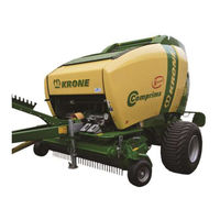
Krone Comprima F 155 XC Original Operating Instructions (430 pages)
Brand:
Krone
| Category:
Farm Equipment
| Size: 12 MB
Table of Contents
Table of Contents
3
Validity
9
Re-Ordering
9
Further Applicable Documents
9
Target Group of this Document
9
How to Use this Document
9
Directories and References
9
To this Document
9
Scope of Document
10
Means of Representation
10
Term "Machine
10
Figures
10
Direction Information
10
Conversion Table
13
Safety
14
Purpose of Use
14
Intended Use
14
Service Life of the Machine
14
Personnel Qualification of the Technicians
15
Personnel Qualification of the Operating Personnel
15
Importance of the Operating Instructions
15
Basic Safety Instructions
15
Children in Danger
16
Coupling the Machine Safely
16
Structural Changes to the Machine
16
Additional Equipment and Spare Parts
16
Workstations on the Machine
16
Operational Safety: Technically Perfect Condition
17
Danger Zones
19
Personal Protective Equipment
21
Keeping Safety Devices Functional
21
Safety Signs on the Machine
22
Traffic Safety
22
Parking the Machine Safely
23
Consumables
23
Dangers Associated with the Operational Environment
23
Sources of Danger on the Machine
25
Dangers Associated with Certain Activities: Climbing up and down
26
Dangers Associated with Certain Activities: Work on the Machine
26
Dangers Associated with Certain Activities: Working on Wheels and Tyres
27
Behaviour in Hazardous Situations and When Accidents Occur
27
Supporting Lifted Machine and Machine Parts Securely
28
Stopping and Securing the Machine
28
Safety Routines
28
Safely Checking the Oil Level and Changing the Oil and Filter Element
29
Running the Actuator Test
29
Safety Stickers on the Machine
31
Position and Meaning of the Safety Stickers on the Machine
31
Re-Ordering Safety Labels and Information Labels
48
Attaching Safety Labels and Information Labels
48
Contact
48
Parking Brake
49
Safety Equipment
49
Attaching the Safety Cable
50
Parking Support
51
Wheel Chocks
54
Stop Points
55
Shut-Off Valve for Tailgate
56
SMV Emblem
57
Data Memory
58
Machine Description
60
Machine Overview
60
Identification Plate
61
Technical Data of the Machine
62
Technical Data
62
Hydraulic Connections
67
Consumables
67
Ambient Temperature
68
Commissioning
69
Before Initial Start-Up
69
Dismounting the Transport Tensioning Device
73
Mounting the Bale Ejector
74
Adjusting the Drawbar Height
80
PTO Shaft
82
Mounting the Protective Cap for the Universal Shaft of the Tractor
82
Mounting the Universal Shaft at the Machine
83
Length Adjustment
86
Mounting the Hose and Cable Support
87
Preparing the Wrapping Material Brake
87
Checking/Setting the Tyre Pressure
88
Bleed the Friction Clutch on the Universal Shaft
88
KRONE Operation Unit Alpha
89
Overview
89
General Description
89
Mounting the Control Unit
90
Control Unit
91
Operational Readiness
92
Operating Machine Functions
93
Operation of Tying (Manual Mode)
93
Operation of Tying (Automatic Mode)
94
Settings and Diagnostics
95
Setting Net Layers
95
Adjusting the Automatic Blocking Time
96
Adjusting the Engine Position (Net)
96
Adjusting the Feed Position
97
Adjusting the Cut-Off Position
97
Approaching Tying Position
98
Sensor Test Digital
99
Sensor Test Analogue
100
Displays and Signals
101
Baling Pressure Setting (Comprima F125 / F155 Medium) or Bale Diameter (Comprima V 150 / V 180)
101
Displays "Version Number
102
Acoustic and Visual Signals and Their Meaning
102
Start-Up
103
Connect the Machine to the Tractor
104
Hydraulics
105
Special Safety Instructions
105
Connecting the Hydraulic Lines
106
Hydraulic Brake (Auxiliary Brake)
108
Hydraulic Brake (Export)
108
Install the PTO Shaft
109
Compressed Air Connections for the Compressed Air Brake
111
Connecting the Road Lighting
112
Using the Safety Chain
113
Driving and Transport
115
Preparations for Road Travel
116
Lift Pick-Up
116
Checking the Parking Support
116
Checking the Road Lighting System
117
Putting Wheels Chocks Underneath
118
Switching off the Machine
118
Moving Parking Support into Support Position
119
Disconnecting the PTO Shaft from the Tractor
119
Disconnecting the Supply Lines
119
Preparing the Machine for Transportation
120
Raising the Machine
120
Securing the Side Hoods
121
Securing the Twine Box Flap
121
Mounting Transport Tensioning Device
122
Operation
123
Adjustments before Starting Work
123
Travelling Speed
124
Filling the Bale Chamber
125
Reducing the Pressure on the Side Walls of the Bale Chamber
126
Mounting Additional Driver Guide Rails on the Starter Roller
127
Mounting Additional Deflector Sheets in the Tailgate
128
Wrapping and Depositing Bales
130
Driving with Bale Ejector
131
Before Baling
132
Tensioning the Floor Conveyor
132
Drive Chain for Pick-Up with Cam-Type Clutch
133
Overload Protection
133
After Baling
133
Pick-Up
134
Adjusting the Working Height
134
Adjusting the Pick-Up Height more Precisely
135
Adjusting the Bearing Pressure Relief for the Pick-Up
136
Setting the Crop Press Roller Unit
137
Setting the Baffle Sheet
138
Cutting System
139
General Aspects
139
Cutting Length
140
Setting Bale Diameter
143
Preselecting Bale Diameter (Comprima V 150 (XC) / V 180 (XC) / V 210 XC) (Medium Electronics)
144
Setting of Bale Diameter Display (Comprima V 150 (XC) / V 180 (XC) / V 210 XC) (Medium Electronics)
145
Setting Baling Pressure
146
Setting of the Baling Pressure Display (Medium Electronic System)
148
Setting Tailgate Catch (Medium Electronic System)
149
Twine Tying (for Version with "Twine and Net Tying")
150
Overview
150
Tying Function
151
Setting the Tying Twine in Place
152
Setting the Number of Twine Layers
155
Further Settings for Twine Tying
156
Net Wrapping
157
Functionality of the Net Wrapping
157
Inserting Net Roll
158
Insert Net
159
Adjusting the Feed, Cut-Off and Tying Position
160
Setting the Number of Net Layers
160
Net and Chamber Film Wrapping
161
Functionality of the Net and Chamber Film Wrapping
161
Inserting a Net or Film Roll
162
Insert Net
163
Inserting Sheet
165
Setting the Number of Net or Film Layers
167
Notes on Operation with Chamber Film Wrapping
167
Checking the Stretching of the Inserted Film
168
Tighten the Floor Conveyor and Set the Spring Pretensioning
169
Checking the Tension Springs of the Final Density Display
171
Setting the Density of the Bale Core
171
Removing the Crop Blockages in the Crop Collection Area
175
Crop Blockage at Pick-Up
176
Crop Blockage under the Cutting Rotor
177
Crop Blockage in the Baling Element
178
Reversing Device
179
Settings
181
Setting the Brake Force Release During the Feeding Process
182
Setting the Wrapping Material Brake
183
Setting the Wrapping Material Brake
184
Locking/Releasing the Clamping Lever
186
Checking Retaining Comb for Net Tying
188
Checking the Retaining Comb for Film Tying
189
Setting the Retaining Comb for Film Tying
190
Checking the Position of the Feed Rocker Arm
192
Adjusting the Twine Limiter
194
Adjusting the Wire Rope for "Loosen Twine Brake
195
Adjusting the Distance between the Front and Rear Net Roller
196
Setting the Twine Brake
197
Adjusting the Pressure Roller
198
Setting the Magnetic Transmission
199
Adjusting the Cutting Blade on the Tying Unit
200
Central Chain Lubrication System
201
Maintenance
205
Spare Parts
205
Maintenance Table
206
Metric Thread Screws with Control Thread
207
Tightening Torques
207
Metric Thread Screws with Fine Thread
208
Metric Thread Screws with Countersunk Head and Hexagonal Socket
208
Tightening Torques for Locking Screws and Bleed Valves on the Gearboxes
209
Setting Scraper to Spiral Roller
210
Adjusting the Scraper
212
Setting the Stone Deflector
213
Setting Tailgate Lock
214
Position of the Sensors
215
Setting the Sensors
221
Checking and Setting the Axial Play of the Brake Disc at the Wrapping Material Brake
221
Removing Paint and Welding Residues before Commissioning with Chamber Film Wrapping
222
Bleed the Friction Clutch on the Universal Shaft
223
Brakes
224
Checking the Brake Setting
224
Adjusting the Cam Brake
224
Settings of the Brakes with Manual Linkage Setter
225
Setting Brake Linkage
227
Tyres
229
Checking and Maintaining Tyres
230
Drawbar
232
Hitches on the Drawbar
232
Oil Level Check and Oil Change on the Gearboxes
233
Time Intervals for Oil Level Check and Oil Change on the Gearboxes
233
Main Drive
234
Novo Grip Belt on the Floor Conveyor
235
Checking the Safety Rollers of Single Blade Locking Device
235
Checks and Maintenance on Rear Floor Conveyor
236
Adjusting the Deflection Roller
237
Setting the Drive Chains
238
Floor Conveyor Drive
238
Pick-Up
240
Roller Drive
243
Conveyor Auger Drive
243
Changing Blades
244
Grinding Blades
248
Moving Blade Retaining Shaft
249
Maintenance - Brake System (Special Equipment)
250
Coupling Heads (Non-Interchangeable)
251
Air Filter for Pipelines
252
Compressed-Air Reservoir
253
Maintenance - Lubrication
254
Special Safety Instructions
254
Lubricating Universal Shaft
255
Lubricants
255
Lubrication Chart
256
Maintenance - Hydraulic System
264
Shut-Off Valve for Tailgate
265
Prior to Working on the Hydraulic System
265
Solenoid Valves
266
Replacing the Hydraulic Oil Filter
267
Circuit Diagrams of the Hydraulic System
268
Malfunctions - Causes and Remedies
269
General Malfunctions
270
Malfunctions on the Central Chain Lubrication System
274
Malfunctions During Twine Tying
275
Error Messages of KRONE Operation Terminal
276
Placing in Storage
277
At the End of the Harvest Season
277
Before the Start of the New Season
278
Maintenance Work before the Beginning of the New Season
279
Disposal of the Machine
281
ISOBUS Terminal
282
Advertisement
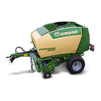
Krone Comprima F 155 XC Original Operating Instructions (398 pages)
Brand:
Krone
| Category:
Lawn and Garden Equipment
| Size: 11 MB
Table of Contents
1 Table of Contents
3
2 To this Document
11
Validity
11
Re-Ordering
11
Further Applicable Documents
11
Target Group of this Document
11
How to Use this Document
11
Directories and References
11
Direction Information
12
Term "Machine
12
Figures
12
Scope of Document
12
Means of Representation
12
3 Safety
15
Purpose of Use
15
Intended Use
15
Service Life of the Machine
15
Basic Safety Instructions
16
Importance of the Operating Instructions
16
Personnel Qualification
16
Children in Danger
17
Connect the Machine to the Tractor
17
Structural Changes to the Machine
17
Additional Equipment and Spare Parts
17
Workstations and Passengers
17
Operational Safety: Technically Perfect Condition
18
Danger Zones
19
Keeping Safety Devices Functional
21
Personal Protective Equipment
21
Safety Signs on the Machine
22
Traffic Safety
22
Parking the Machine Safely
23
Consumables
23
Dangers Associated with the Operational Environment
23
Sources of Danger on the Machine
24
Dangers Associated with Certain Activities: Climbing up and down
25
Dangers Associated with Certain Activities: Work on the Machine
25
Dangers Associated with Certain Activities: Working on Wheels and Tyres
26
Behaviour in Hazardous Situations and When Accidents Occur
26
Safety Routines
27
Stopping and Securing the Machine
27
Supporting Lifted Machine and Machine Parts Securely
27
Coupling the Machine Safely
28
Uncoupling the Machine Safely
28
Preparing the Machine for Repair, Maintenance and Adjustment Work
29
Starting the Machine Safely
29
Safety Stickers on the Machine
31
Position and Meaning of the Safety Stickers on the Machine
31
Re-Ordering Safety Labels and Information Labels
48
Attaching Safety Labels and Information Labels
48
Contact
48
Safety Equipment
49
Parking Brake
49
Attaching the Safety Cable
50
Parking Support
51
Wheel Chocks
54
Stop Points
55
Shut-Off Valve for Tailgate
56
Step for Working on the Linkage
57
Identification Plate
58
Information Required for Questions and Orders
58
4 Data Memory
59
5 Technical Data
60
Technical Data of the Machine
60
Hydraulic Connections
65
Consumables
65
Ambient Temperature
65
6 KRONE Operation Unit Alpha
66
Overview
66
General Description
66
Mounting the Control Unit
67
Control Unit
68
Operational Readiness
69
Operating Machine Functions
70
Operation of Tying (Manual Mode)
70
Operation of Tying (Automatic Mode)
71
Settings and Diagnostics
72
Setting Net Layers
72
Adjusting the Automatic Blocking Time
73
Adjusting the Engine Position (Net)
73
Adjusting the Feed Position
74
Adjusting the Cut-Off Position
74
Approaching Tying Position
75
Sensor Test Digital
76
Sensor Test Analogue
77
Displays and Signals
78
Baling Pressure Setting (Comprima F125 / F155 Medium) or Bale Diameter (Comprima V 150 / V 180)
78
Displays "Version Number
79
Acoustic and Visual Signals and Their Meaning
79
7 KRONE Terminal BETA II
80
Installing and Connecting Terminal
80
Installing Terminal in the Tractor Cabin
80
Connecting Terminal
80
ISOBUS Shortcut Button Not Available
81
Switching Terminal on or off
82
Display Design
83
Status Line
83
Keys
84
Main Window
84
Switching between the Terminals
87
8 KRONE ISOBUS Terminal
89
General Information on ISOBUS
89
Installing and Connecting Terminal
89
Installing Terminal in the Tractor Cabin
89
Connecting the Terminal (Trailed Machines (ISOBUS Capable Tractor))
90
Connecting the Terminal (Trailed Machines (Tractor Is Not ISOBUS Capable))
92
ISOBUS Shortcut Button
94
Touch Sensitive Display
95
Switching Terminal on or off
96
Display Design
97
Status Line
97
Keys
98
Main Window
98
Switching between the Terminals
101
9 Foreign Terminal ISOBUS
102
General Information on ISOBUS
102
Installing and Connecting Terminal
103
Installing Terminal in the Tractor Cabin
103
Connecting the Terminal
103
ISOBUS Shortcut Button Not Available
104
Deviating Functions from KRONE ISOBUS Terminal
104
Switching between the Terminals
104
10 Terminal - Machine Functions
105
General Information on Functioning of Machine and Terminal
105
Operating Machine Functions
106
Setting Bale Diameter
108
Setting Baling Pressure
109
Operating Hydraulic Blade Group Control System
110
Auxiliary Functions for ISOBUS Terminals
112
Example of Joystick Assignment for Fendt (Default Setting)
113
Recommended Settings for a WTK Multi-Function Lever (Default Setting)
114
11 Terminal - Menus
115
Operating Menus
115
Calling the Basic Screen
115
Bringing up a Menu Level
115
Selecting Menus
116
Entering Values
119
Calling and Saving Machine Settings
120
Icons for Settings in the Menus
120
Menus in the Terminal
122
Menu Structure
122
Menu Level
124
Menu 1 "Number of Net Layers" (Net Tying)
126
Menu 1 "Number of Film Layers" (Film Tying)
127
Menu 2 "Number of Twine Layers" (Twine Tying)
128
Menu 3 "Pre-Signalling
129
Menu 4 "Tying Start Delay" (Twine Tying)
130
Menu 4 "Tying Start Delay" (Net Tying)
131
Menu 4 "Tying Start Delay" (Film Tying)
132
Menu 5 "Bale Diameter" (Comprima F 125 (XC), F 155 (XC))
133
Menu 6 "Electronical Baling Pressure Adjustment" (Comprima V 150 (XC), V 180 (XC)
134
Menu 7 "Sensitivity Direction Display (Comprima F 125 (XC), F 155 (XC))
135
Menu 8 "Selection Type of Tying" (for Version with Net Tying and Twine Tying)
136
Menu 8 "Selection Type of Tying" (for Version with Net and Film Tying)
137
Menu 9 "Correction Filling" (Comprima V 150 (XC), V 180 (XC), V 210 XC)Menus: Correction Filling
138
Menu 10 "Manual Operation" (for Version with Net Tying)
139
Menu 10 "Manual Operation (for Version with Net Tying and Twine Tying)
141
Menu 10 "Manual Operation" (for Version with Net and Film Tying)
143
Menu 13 "Counters
145
Menu 13-1 "Customer Counter
146
Menu 13-2 "Total Counter
147
Menu 14 "ISOBUS Settings
148
Menu 14-1 "Diagnostics Auxiliary (AUX)
149
Menu 14-3 "Setting Background Colour
150
Menu 14-7 "Switching over Number of Keys
151
Menu 14-9 "Switching between the Terminals
152
Menu 15 "General Settings
153
Menu 15-1 "Sensor Test
154
Menu 15-2 "Actuator Test
158
Menu 15-5 "Software Information
160
Menu 15-6 "Technician Level
161
Alarm Messages
162
Alarm Message Occurs
162
Notes and Alarm Messages
163
Physical Messages
170
Alarms
172
Acoustic Warnings
173
12 Commissioning
175
Before Initial Start-Up
175
Dismounting the Transport Tensioning Device
181
Assembling the Bale Ejector
182
Adjusting the Drawbar Height
188
PTO Shaft
190
Length Adjustment
190
Mounting the PTO Shaft on the Machine Side
191
Attaching the Guard Cup for Universal Shaft
194
Mounting Hose Support
195
Net Brake
196
Installation of Lighting System
196
Krone Comprima F 155 XC Original Operating Instructions (366 pages)
Round baler
Brand:
Krone
| Category:
Farm Equipment
| Size: 18 MB
Table of Contents
Foreword
3
Table of Contents
4
Introduction
12
Purpose of Use
12
Contact
12
Identification Plate
13
Information Required for Questions and Orders
13
Intended Use
14
Technical Data
15
Technical Data Comprima F 125/ Comprima F 125 XC
15
Technical Data Comprima F 155/ Comprima F 155 XC
16
Technical Data Comprima V 150/ Comprima V 150 XC
17
Technical Data Comprima V 180/ Comprima V 180 XC
18
Technical Data Comprima V 210/ Comprima V 210 XC
19
Safety
20
Identifying Symbols in the Operating Instructions
20
Identification of the Hazard Warnings
20
Basic Safety Instructions
21
Personnel Qualification and Training
21
Dangers in Case of Non-Compliance with the Safety Instructions
21
Safety-Conscious Work Practices
21
Safety Instructions and Accident Prevention Regulations
22
Hitched Implements
23
PTO Operation
24
Hydraulic System
25
Tyres
25
Maintenance
26
Working in the Vicinity of Power Transmission Lines
26
Unauthorised Conversion/Modification and Spare Parts Production
27
Inadmissible Modes of Operation
27
Safety Instructions on the Machine
27
Position of the Adhesive Safety Stickers on the Machine
28
Re-Ordering the Adhesive Safety and Information Labels
32
Affixing the Adhesive Safety and Information Labels
32
Safety Routines
33
Stopping and Securing the Machine
33
Supporting Lifted Machine and Machine Parts Securely
33
Coupling the Machine Safely
34
Uncoupling the Machine Safely
34
Preparing the Machine for Repair, Maintenance and Adjustment Work
35
Starting the Machine Safely
35
Safety Equipment
36
Parking Brake
36
Attaching the Safety Cable
37
Parking Support
38
Lowering the Parking Support
38
Wheel Chocks
39
Secure the Machine against the Possibility of Rolling Back
39
Stop Points
40
Lifting Eyes
40
Lifting
40
Shut-Off Valve for Tailgate
41
Step for Working on the Linkage
42
Commissioning
43
Before Initial Start-Up
43
Removing the Transport Holding down Tensioning Device
48
Assembling the Bale Ejector
50
Adjusting the Drawbar Height
56
PTO Shaft
58
Length Adjustment
58
Mounting the PTO Shaft on the Machine Side
59
Attaching the Guard Cup for Universal Shaft
62
Hose Holder Assembly
63
Net Brake
64
Installation of Lighting System
64
KRONE Operation Terminal Alpha
65
General Description
65
Mounting the Control Unit
66
Control Unit
67
Operational Readiness
68
Adjusting the Net Wrappings
69
Baling Pressure Setting (Comprima F125 / F155 Medium) or Bale Diameter (Comprima V 150 / V 180)
70
Operation of Tying (Manual Mode)
71
Operation of Tying (Automatic Mode)
72
Settings and Diagnostics
73
Adjusting the Automatic Blocking Time
73
Adjusting the Engine Position (Net)
73
Adjusting the Feed Position
74
Adjusting the Cut-Off Position
74
Approaching Tying Position
74
Sensor Test Digital
76
Sensor Test Analogue
77
Displays "Version Number
78
Acoustic and Visual Signals and Their Meaning
78
KRONE Operation Terminal Beta
80
Attachment of Control Unit
81
Electrical Power Supply
81
Description of the Keys
82
Operational Readiness
83
Basic Screen
84
Functions of Keys 1 - 3
84
Selecting Manual or Automatic Mode
85
Selecting Pick-Up or Blade Base
85
Displays in the Main Window
86
Messages
87
Setting Bale Firmness
88
Setting Bale Diameter and Bale Firmness
88
Setting Bale Diameter
89
Menu Level
90
Short Overview
90
Bringing up a Menu Level
92
Main Menu 1 "Settings
94
Menu 1-1 "Contrast
95
Menu 1-2 "Bale Diameter" (Comprima F155 (XC))
96
Menu 1-3 "Number of Net Winds
97
Menu 1-4 "Sensitivity of Direction Display" (Comprima F125/F155 (XC))
98
Menu 1-5 „Pre-Signalling
100
Menu 1-6 „Correction Filling
102
Menu 1-9 „Tying Start Delay
104
Main Menu 2 „Counter
105
Menu 2-1 "Customer Counters
106
Menu 2-2 "Total Bale Counter
108
Main Menu 3 „Manual Operation
110
Main Menu 4 "Service
112
Menu 4-2 "Manual Sensor Test
113
Menu 4-4 „Manual Actuator Test
120
Menu 4-7 "Position Motor
123
Main Menu 5 "Info
125
Main Menu 6 „Technician
126
Alarm Messages
126
Note and Messages
127
Physical Messages
129
General Messages
130
KRONE ISOBUS-Terminal CCI 100
132
Installing the Terminal into Cabin
133
ISOBUS Short Cut Button
134
Display / Touchscreen
135
Connecting the Terminal (on Tractors with Integrated ISOBUS System)
136
Connecting the Terminal (on Tractors Without ISOBUS System)
137
Switching the Terminal on / off When the Machine Is Not Connected
138
Switching the Terminal on / off When the Machine Is Connected
139
Basic Screen
140
Setting the Setpoint Bale Firmness
144
Setting the Target Bale Diameter
145
Messages
146
Menu Level
147
Short Overview
147
Calling up the Menu Level
149
Main Menu 1 "Settings
150
Menu 1-2 „Bale Diameter" (Comprima F155 (XC))
151
Menu 1-3 „Number of Net Winds
152
Menu 1-4 "Sensitivity of the Direction Display" (Comprima F125/F155 (XC))
153
Menu 1-5 „Pre-Signalling
154
Menu 1-6 „Correction Filling
156
Menu 1-9 „Tying Start Delay
158
Main Menu 2 „Counter
159
Menu 2-1 "Customer Counter
160
Menu 2-2 „Total Bale Counter
162
Main Menu 3 „Manual Operation
163
Menu 3-2 "Net Motor Position
164
Main Menu 4 „Service
165
Menu 4-2 „Manual Sensor Test
166
Menu 4-4 Manual Actuator Test
173
Main Menu 5 "Info
176
Main Menu 6 Technician
177
Main Menu 7 ISOBUS
178
Menu 7-1 Virtual Terminal (VT)
179
Menu 7-1-1 Select Day/Night Display Lighting
180
Menu 7-1-4 Switch to Different Terminal
181
Menu 7-4 ISOBUS Diagnostics
182
Menu 7-4-2 Diagnostics Auxiliary Functions (AUX)
183
Alarm Messages
184
Acoustic Warnings
185
Note and Messages
186
Physical Messages
187
General Messages
188
Advertisement
Krone Comprima F 155 XC Original Operating Instructions (356 pages)
Brand:
Krone
| Category:
Lawn and Garden Equipment
| Size: 5 MB
Table of Contents
Table of Contents
3
To this Document
10
Validity
10
Re-Ordering
10
Further Applicable Documents
10
Target Group of this Document
10
How to Use this Document
10
Directories and References
10
Direction Information
11
Term "Machine
11
Figures
11
Scope of Document
11
Means of Representation
11
Conversion Table
14
Safety
15
Purpose of Use
15
Intended Use
15
Service Life of the Machine
15
Basic Safety Instructions
16
Importance of the Operating Instructions
16
Personnel Qualification of the Operating Personnel
16
Personnel Qualification of the Technicians
16
Children in Danger
17
Coupling the Machine Safely
17
Structural Changes to the Machine
17
Additional Equipment and Spare Parts
17
Workstations on the Machine
17
Operational Safety: Technically Perfect Condition
18
Danger Zones
20
Keeping Safety Devices Functional
22
Personal Protective Equipment
22
Safety Signs on the Machine
23
Traffic Safety
23
Parking the Machine Safely
24
Consumables
24
Dangers Associated with the Operational Environment
24
Sources of Danger on the Machine
26
Dangers Associated with Certain Activities: Climbing up and down
27
Dangers Associated with Certain Activities: Work on the Machine
27
Dangers Associated with Certain Activities: Working on Wheels and Tyres
28
Behaviour in Hazardous Situations and When Accidents Occur
28
Safety Routines
29
Stopping and Securing the Machine
29
Supporting Lifted Machine and Machine Parts Securely
29
Safely Checking the Oil Level and Changing the Oil and Filter Element
30
Running the Actuator Test
30
Safety Stickers on the Machine
31
Position and Meaning of the Safety Stickers on the Machine
31
Re-Ordering Safety Labels and Information Labels
48
Attaching Safety Labels and Information Labels
48
Contact
49
Safety Equipment
50
Parking Brake
50
Parking Support
51
Wheel Chocks
56
Stop Points
57
Shut-Off Valve for Tailgate
58
SMV Emblem
59
Data Memory
60
Machine Description
62
Machine Overview
62
Identification Plate
63
Information Required for Questions and Orders
63
Technical Data
64
Hydraulic Connections
66
Consumables
66
Ambient Temperature
67
Commissioning
69
Before Initial Start-Up
70
Preparatory Work
70
Checking the Guide Wheel Support before Initial Operation
73
Dismounting the Transport Tensioning Device
74
Mounting the Bale Ejector
75
Adjusting the Drawbar Height
80
PTO Shaft
82
Mounting the Protective Cap for the Universal Shaft of the Tractor
82
Mounting the Universal Shaft at the Machine
83
Length Adjustment
86
Mounting Hose Support
87
Preparing the Wrapping Material Brake
87
Installation of the Lighting System
88
Checking/Setting the Tyre Pressure
88
Start-Up
89
Connect the Machine to the Tractor
90
Hydraulics
91
Special Safety Instructions
91
Connecting the Hydraulic Lines
92
Hydraulic Brake (Export)
94
Hydraulic Brake (Auxiliary Brake)
94
Install the PTO Shaft
95
Compressed Air Connections for the Compressed Air Brake
97
Connecting KRONE BETA II Terminal
98
Connecting KRONE ISOBUS-Terminal
100
Connecting External ISOBUS-Terminal
103
Connecting the Joystick
104
Electrical Connections
107
Using the Safety Chain
108
KRONE BETA II Terminal
110
ISOBUS Shortcut Button Not Available
110
Switching Terminal on or off
111
Display Design
112
Status Line
113
Keys
114
Main Window
114
Switching between the Terminals
116
KRONE ISOBUS Terminal
117
General Information on ISOBUS
117
ISOBUS Shortcut Button
118
Touch Sensitive Display
119
Switching Terminal on or off
120
Display Design
122
Status Line
123
Keys
124
Main Window
124
Switching between the Terminals
126
Foreign Terminal ISOBUS
127
General Information on ISOBUS
127
ISOBUS Shortcut Button Not Available
128
Deviating Functions from KRONE ISOBUS Terminal
128
Terminal - Machine Functions
129
General Information on Functioning of Machine and Terminal
129
Calling Working Screen
130
Working Screen "Status Bale Chamber
130
Operating Machine Functions
131
Setting Bale Diameter
133
Setting Baling Pressure
134
Operating Hydraulic Blade Group Control System
135
Operating Machine Via Joystick
137
Auxiliary Functions (AUX)
137
Auxiliary Assignment of a Joystick
138
Terminal - Menus
140
Menu Structure
140
Calling up the Menu Level
142
Selecting Menu
142
Changing the Value
145
Calling and Saving Machine Settings
146
Icons for Settings in the Menus
146
Menus in the Terminal
147
Menu Level
147
Menu 1 "Number of Net Layers" (Net Tying)
149
Menu 1 "Number of Film Layers" (Film Tying)
150
Menu 3 "Pre-Signalling
151
Menu 4 "Tying Start Delay" (Net Tying)
152
Menu 4 "Tying Start Delay" (Film Tying)
153
Menu 5 "Bale Diameter" (Comprima F)
154
Menu 6 "Electronical Baling Pressure Adjustment" (Comprima V)
155
Menu 7 "Sensitivity of Direction Display"" (Comprima F)
156
Menu 8 "Selection Type of Tying" (for Version with Net and Film Tying)
157
Menu 9 "Correction Filling" (Comprima V)Menus: Correction Filling
158
Menu 10 "Manual Operation" (for Version with Net Tying)
159
Menu 10 "Manual Operation" (for Version with Net and Film Tying)
161
Menu 13 "Counters
163
Menu 13-1 "Customer Counter
164
Menu 13-2 "Total Counter
165
Menu 14 "ISOBUS Settings
166
Menu 14-1 "Diagnostics Auxiliary (AUX)
167
Krone Comprima F 155 XC Original Operating Instructions (278 pages)
Brand:
Krone
| Category:
Lawn and Garden Equipment
| Size: 14 MB
Table of Contents
Table of Contents
3
1 Information on this Document
9
Validity
9
Re-Ordering
9
Applicable Documents
9
Target Group of this Document
9
How to Use this Document
9
Directories and References
9
Figures
10
Information on Direction
10
Conversion Table
12
2 Safety
14
Intended Use
14
Reasonably Foreseeable Misuse
14
Service Life of the Machine
15
Basic Safety Instructions
15
Importance of Operating Instructions
15
Personnel Qualification of the Operating Personnel
15
Personnel Qualification of the Technicians
16
Children in Danger
16
Connecting the Machine
16
Structural Modifications on the Machine
16
Additional Equipment and Spare Parts
16
Jobs on the Machine
17
Operational Safety: Technically Sound Condition
17
Danger Zones
18
Ensuring Functionality of Safety Devices
20
Keeping Universal Shaft Guard Functional
20
Personal Protective Equipment
20
Safety Markings on the Machine
21
Road Safety
21
Parking the Machine Safely
22
Consumables
22
Dangers Arising from Environment
22
Sources of Danger on the Machine
24
Dangers in Connection with Certain Activities: Working on the Machine
25
Dangers in Connection with Certain Activities: Working on Wheels and Tyres
26
Behaviour in Dangerous Situations and in Case of Accidents
27
Safety Routines
27
Shutting down and Safeguarding the Machine
27
Securing Raised Machine and Machine Parts against Lowering
27
Carrying out Oil Level Check and Oil and Filter Element Changes Safely
28
Running Actuator Test
28
Safety Labels on the Machine
29
Safety Equipment
35
SMV Emblem
36
3 Data Memory
37
4 Machine Description
38
Machine Overview
38
Overload Protections on the Machine
38
Identification Plate
39
Function Description Net Wrapping
39
Function Description Net and Chamber Film Wrapping
40
Function Description Cutting Unit
41
5 Technical Data
42
Oils
44
Lubricating Greases
44
6 Initial Operation
45
Scope of Delivery
45
Mounting Hose and Cable Support
46
Preparing the Brake Disc of the Wrapping Material Brake
46
Checking/Adapting the Tyre Pressure
46
Adjusting the Drawbar Height
47
Universal Shaft
49
Adjusting the Length of the Universal Shaft
49
Mounting Protective Cap of Universal Shaft
50
Mounting Universal Shaft Bracket
50
Mounting the Universal Shaft on the Machine
51
Removing the Tensioning Device
51
7 Commissioning
53
Connecting Machine to Tractor
53
Mounting the Universal Shaft on the Tractor
54
Connecting Hydraulic Hoses
55
Connecting Hydraulic Brake (Export)
56
Coupling the Hydraulic Auxiliary Brake
57
Connecting/Disconnecting Compressed Air Connections for the Compressed Air Brake
57
Adjusting Drawbar Eye
58
Connecting the KRONE ALPHA Operation Unit
58
Connecting KRONE Terminal DS 500
59
Connecting KRONE BETA II Terminal
61
Connecting the KRONE ISOBUS Terminal (CCI 800, CCI 1200)
63
Connecting Foreign ISOBUS Terminal
65
Connecting the Camera to the KRONE ISOBUS Terminal CCI 800 or CCI 1200
67
Connecting the Road Lighting
67
Mounting Safety Chain
68
8 Operation
69
Preparation before Baling
69
Filling the Bale Chamber
69
Improving Bale Chamber Filling
71
Reducing the Pressure on the Side Walls of the Bale Chamber
71
Mounting Additional Driver Guide Rails on the Starter Roller
71
Mounting Additional Deflector Sheets in the Tailgate
72
Completing the Baling Process, Starting Tying Cycle and Ejecting Round Bales
73
Operating the Support Jack
73
Using the Stop Cock of the Tailgate
75
Releasing/Applying the Parking Brake
76
Fitting Wheel Chocks
77
Removing/Mounting the Safety Device Which Prevents Unauthorised Use
78
Operating Brake Force Regulator
78
Operating the Bale Counter
79
Pick-Up
79
Bringing the Pick-Up to Transport/Working Position
79
Setting the Pick-Up Working Height
80
Adjusting the Bearing Pressure Relief for the Pick-Up
81
Crop Press Roller Unit
81
Setting the Crop Press Roller Unit
82
Setting the Baffle Sheet on the Crop Press Roller Unit
82
Removing/Mounting the Baffle Sheet on the Crop Press Roller Unit
83
Cutting Unit
84
Lifting/Lowering Blade Cassette
84
Swivelling Blade Groups In/Out
84
Net Wrapping
87
Inserting the Net Roll
87
Insert Net
89
Net and Chamber Film Wrapping
90
Inserting a Net or Film Roll
90
Inserting the Net or Film
91
Notes on Operation
93
Checking the Tension of the Inserted Film
94
Using the Bale Ejector
95
Removing Crop Blockages
95
Crop Blockage at the Right-Hand and Left-Hand End of the Pick-Up
95
Crop Blockage in the Pick-Up
95
Crop Blockage under the Cutting Rotor
96
Crop Blockage in the Baling Element
97
Operating the Central Chain Lubrication System
97
9 KRONE ALPHA Operation Unit
100
Overview
101
Switching the Operation Unit On/Off
102
Start Tying Process in Manual Mode
102
Starting Tying in Automatic Mode
102
Setting the Net Layers
103
Setting the Automatic Blocking Time
103
Digital Sensor Test
104
Analogue Sensor Test
105
Setting the Feed and End Position of the Feed Rocker Arm
105
Display Filling
106
Showing the Software Version Number
106
10 KRONE Beta II Terminal
107
ISOBUS Shortcut Button Not Available
107
Switching Terminal On/Off
108
Design of Display
109
11 KRONE Terminal DS 500
110
Touchable Display
110
KRONE Terminal DS 500
110
Design DS 500
111
12 KRONE ISOBUS Terminal (CCI 800, CCI 1200)
113
Touchable Display
113
Switching Terminal On/Off
114
Design of Display
115
Design of the KRONE Machine Application
115
Setting Units on the Terminal
116
Krone Comprima F 155 XC Original Operating Manual (234 pages)
Brand:
Krone
| Category:
Lawn and Garden Equipment
| Size: 5 MB
Table of Contents
Table of Contents
3
1 General Aspects
11
Intended Use
11
Technical Data
11
Manufacturer's Address
11
Declaration
11
Identification
11
Data Required for Questions and Orders
11
Operation in Accordance with Intended Use
12
General Technical Data
12
Technical Data - COMPRIMA F 125/ COMPRIMA F 125 XC
13
Technical Data - COMPRIMA F 155/ COMPRIMA F 155 XC
14
Technical Data - COMPRIMA V 150 / COMPRIMA V 150 XC
15
Technical Data - COMPRIMA V 180 / COMPRIMA V 180 XC
16
2 Safety
17
Identifying Important Information in the Operating Instructions
17
Safety Instructions and Accident Prevention Regulations
17
Personnel Qualification and Training
17
Dangers in the Case of Non-Compliance with the Safety Iinstructions
17
Safety-Conscious Working
17
Safety Instructions and Accident Prevention Regulations
18
Hitched Implements
19
PTO Operation
19
Hydraulic System
19
Tyres
20
Maintenance
20
Unauthorised Modifications and Spare Parts Production
20
Prohibited Modes of Operation
20
Introduction
21
Location of Safety Stickers on the Machine (COMPRIMA F 125 ; COMPRIMA F155
21
Location of General Information Labels on the Machine (COMPRIMA F 125 ; COMPRIMA F155
24
Location of Safety Stickers on the Machine (COMPRIMA V 150; COMPRIMA
26
Location of General Information Labels on the Machine (COMPRIMA V 150; COMPRIMA
30
3 Before and after Use
33
Commissioning
33
Hitching
34
Connecting the Hydraulic Hoses (COMPRIMA F 125; F 155)
34
(Comprima V150; V 180)
46
Use
46
After Pressing
47
Comprima V 150/V 180 /V150
47
5 Basic Settings and Operation
49
Special Safety Instructions
49
Pick-Up
49
Roll-Type Crop Guard (Special Equipment
49
Bearing Pressure Relief of the Pick-Up
50
Cutting System
51
Special Safety Instructions
51
General Aspects
51
Adjusting the Cutting Length
51
Clogging of the Cutting System
53
Changing Cutters
54
Compression Pressure Setting (COMPRIMA
57
Setting the Bale Diameter (COMPRIMA
57
Adjusting Baling Diameter (COMPRIMA V 150 ,V 180) (Medium
58
Compression Pressure Setting (COMPRIMA
59
Setting Bale Diameter Indicator (COMPRIMA V 150 ,V 180)(Medium
60
Setting the Rear Flap Locking Mechanism (Medium
61
Setting of the Bale Firmness Indicator (Medium
61
Net Wrapping
62
Special Safety Instructions
62
Components
62
General Aspects
62
Inserting the Netting Roll
63
Feed the Net
64
Setting the Net Brake
65
Adjusting the Cut-Off Position
67
Adjusting the Feed Position
67
Tying Position
68
Setting the Number of Net Winds
68
Adjusting Belt Motion for the Rear Floor Conveyor (COMPRIMA V150 / V180
69
Bale Counter
70
Clamping the Floor Conveyor (COMPRIMA F125
70
Adjusting Soft Core
71
Central Chain Lubrication (Special Equipment
73
Oil Flow Rate Setting (Cam Pump
74
Central Chain Lubrication" Diagram
74
Advertisement
Related Products
Krone Comprima F 155
Krone COMPRIMAF F 1551 XC
Krone Comprima F 125
Krone Comprima F 125 XC
Krone Comprima V 150 XC
Krone Comprima V 180
Krone Comprima V 180 XC
Krone Comprima V 150
Krone Comprima V 210 XC
Krone Comprima CF 155 XC
Krone Categories
Farm Equipment
Lawn Mower
Lawn and Garden Equipment
Industrial Equipment
Utility Vehicle
More Krone Manuals
Login
Sign In
OR
Sign in with Facebook
Sign in with Google
Upload manual
Upload from disk
Upload from URL