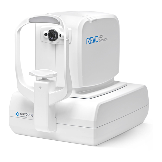
Optopol SOCT Copernicus REVO Service Manual
Hide thumbs Also See for SOCT Copernicus REVO:
Table of Contents

Advertisement

Manufacturer:
OPTOPOL
Technology Sp z o.o.
ul. Żabia 42
42-400 Zawiercie
POLAND
www.optopol.com
info@optopol.com.pl
service@optopol.com.pl
SOCT Copernicus REVO/ REVO NX
Service Manual
FOR DISTRIBUTORS USE ONLY
Rev 2.0
(01-07-2017)
0197

Advertisement

Table of Contents
loading

Summary of Contents for Optopol SOCT Copernicus REVO

  • Page 1 Manufacturer: OPTOPOL Technology Sp z o.o. ul. Żabia 42 42-400 Zawiercie POLAND www.optopol.com info@optopol.com.pl service@optopol.com.pl SOCT Copernicus REVO/ REVO NX Service Manual FOR DISTRIBUTORS USE ONLY Rev 2.0 (01-07-2017) 0197...
  • Page 2: Table Of Contents

    3.6.2 After use ..........................15 SOCT Copernicus REVO SOFTWARE......................15 Running SOCT Copernicus REVO application ......... Błąd! Nie zdefiniowano zakładki. PC installation..................Błąd! Nie zdefiniowano zakładki. Minimum system requirements ............ Błąd! Nie zdefiniowano zakładki. Motherboard drivers installation ..........Błąd! Nie zdefiniowano zakładki.
  • Page 3 Image Source camera ..............Błąd! Nie zdefiniowano zakładki. e2v camera ..................Błąd! Nie zdefiniowano zakładki. SOCT Copernicus REVO software installation........Błąd! Nie zdefiniowano zakładki. Troubleshooting ............................71 Installation troubleshooting ......................71 Electronic troubleshooting ......................73 Optical troubleshooting ........................74 Maintenance check procedure........................ 77 General condition check.
  • Page 4 12.5 Power supply module replacement....................135 12.6 CPU replacement ........................... 137 12.7 Scanner control boards replacement(X,Y scanner set) ..............140 12.8 Spectrometer alignment control module replacement ..............143 12.9 Internal fixation module replacement..................143 12.10 Position sensors replacement ....................144 12.10.1 Right-left/ back-forward movement position sensors replacement.
  • Page 5: Introduction

    TeamViewer software. Customer module available for download at: www.dane.optopol.com In case device return to Optopol Technology Sp z o.o. an RMA form has to be attached to packing box. In order to request it please contact Service Division by mail: service@optopol.com.pl...
  • Page 6: Technical Data

    2. TECHNICAL DATA Signal source Super Luminescent Diode (SLED) Minimum power output directly from SLED SOCT Copernicus REVO 3,5 mW +/-5% REVO NX 5,0 mW +/-5% Wave Length SOCT Copernicus REVO 830 nm REVO NX 830 nm – 850 nm typical 840nm...
  • Page 7 Screen resolution: Minimum 1920 x 1080 Communication ports 1 available USB 3.0 port 2 available USB minimum 2.0 ports Mouse Mouse Wheel Touch screen Recommended 2.2.2 Review station Processor Intel® Core™ i5 2.4 GHz or higher No of cores: min. 2 physical cores, 4 logical min.
  • Page 8: Safety Instructions

    2.3 Safety instructions. CAUTION Follow operating instruction Indicates a fuse is present near this symbol On / Off Type B Applied Parts Date of manufacture Manufacturer Electrical and Electronic Equipment waste. Do not throw the product away with normal household waste at the end of its life. Sign of conformity with essential requirements –...
  • Page 9: Unpacking And Installation

    11. Isolating transformer (optional) 3.1 Unpacking and installation This section describes how to unpack the device shipped from a factory. The SOCT Copernicus REVO/ REVO NX is shipped in a carton box, which protects it from mechanical damages during transport.
  • Page 10: Cables Connection

    Always operate the device within operating ranges of temperature and humidity see user manual Transport position of the SOCT Copernicus REVO/ REVO NX is to be set by turning it off and on-device will go to base position. Turn it off and pack to the box securing with foams.
  • Page 11 NOTE: Regarding EMC (Electro-magnetic compatibility) standards all signal cables have to be put together.
  • Page 12: Proper Device Connection

    3.3 Proper device connection The SOCT Copernicus REVO/ REVO NX is connected to the PC using USB 3.0 cable. NOTE: The SOCT Copernicus REVO/ REVO NX must be directly plugged into the mains with protective earth. Connect the PC, printer and monitor into the multiple portable socket-outlet, which is directly connected to the Isolating Transformer.
  • Page 13: Safety Standards

    The SOCT Copernicus REVO/ REVO NX system complies with all requirements of the directive 93/42/EEC (MDD - Medical Devices Directive). The SOCT Copernicus REVO/ REVO NX is type B applied parts (chin rest support and forehead support ) and class I protection against electric shock.
  • Page 14 SOCT Copernicus REVO/ REVO NX has been classified as CLASS 1 laser device IMPORTANT: 1. If the whole Medical System has been installed by Manufacturer of SOCT Copernicus REVO/ REVO NX or Authorized Personnel, the manufacturer guarantees correct installation and compliance with all required standards and directives.
  • Page 15: Notes On Use

    After using the SOCT device, turn off the power, attach the objective lens cap to protect the objective lens from dust and place the dust cover over the device. 4. SOCT Copernicus REVO/ REVO NX software and drivers installation 4.1 Proper steps selection! Must read! Before starting to operate SOCT application it is necessary to prepare the operating system, install SOCT Copernicus REVO/ REVO NX drivers and install SOCT application.
  • Page 16 For upgrade/ fresh installation of SOCT 7.1.0 it is necessarily to perform camera and device firmware upgrade. In case upgrade is not performed the PC will not recognize SOCT Revo/NX device(DISCONECTED status in software) Besides that it is mandatory to perform Windows OS update. Detailed manual is located in APPENDIX A.
  • Page 17 5. OS Windows 7 configuration To effect the procedure of preparation of operating system you need a user account with Admin rights. 5.1 Screen resolution 1. The SOCT application requires a Full HD screen resolution of 1920 x 1024 pixels. 2.
  • Page 18 5.2 Configure Power balance plan and screen saver 1. SOCT Copernicus REVO device and application require modified power plan settings. Set the screen saver, power options on the computer as shown in the table. Below, you will find detailed instructions.
  • Page 19 4. In section ‘Screen saver’ select ‘(None)’ item, Uncheck check box ‘On resume, display logon screen’. Then click on ‘Change power settings’. 5. On a ‘Balanced’ recommended power plan, click ‘Change plan settings’ 6. Click on ‘Change advanced power settings’...
  • Page 20 7. Click on [Hard disk] → [Turn off hard disk after] → select “Never”. 8. Then, click on [Sleep] → [Sleep after] → select “Never”, [Allow hybrid sleep] → select “Off”, [Hibernate after] → select “Never”. 9. Then, click on [Display] → [Turn off the display after] → select „Never”.
  • Page 21 10. To apply modified power plan, click on [OK] button. 11. In a ‘Turn off the display’ field select “Never” and in ‘Put the computer to sleep’ select ‘Never’. Click on [Save changes] button to close the window.
  • Page 22 5.3 Windows Update To run SOCT Copernicus REVO application properly it is required to install the newest Microsoft Windows updates. After finishing updating the Windows it is required to switch off automatic updates. NOTE: Before Windows Update process starts, network connection should be established.
  • Page 23 5. At the end, system displays information about number of available updates. To start installation, click on [Install updates] button. 6. System starts downloading updates. The process starts automatically and may take several minutes. 7. At the end of downloading process, confirm the License Terms by checking ratio button ‘I accept the license terms’.
  • Page 24 9. Repeat steps from 3 to 8 until information ‘There are no updates available for your computer’ appears. 10. Install also optional updates especially if they are referring to USB ports communication.
  • Page 25 5.3.2 Disable automatic Windows updates. 1. After installing updates it is required to switch off Automatic Updates. Click on Start → Control Panel → System and Security → Windows Update → Change settings. at Form ‘Important updates’ list select ‘Never check for updates (not recommended)’ item and click on [OK] button.
  • Page 26 2. Uncheck check boxes ‘Windows Update’, ‘Check for updates’ and ‘Virus protection’. To continue, click on [OK] button. 5.3.4 Uninstall Windows 10 update reminder number KB3035583 In case Device and software will be used on Windows 10 below point is not applicable. For safety reasons it is recommended to remove tool Windows 10 upgrade reminder.
  • Page 27 7. On the list of available updates to install find package number KB3035583. Click right mouse button, then from submenu select ‘Hide update’. Click [OK] to close this window. 5.4 Antivirus protection It is recommended to use Antivirus protection. IMPORTAINT NOTE: Each antivirus protection software has to have exceptions for SOCT installation folder and all SOCT software components.
  • Page 28 3. Click on [I Accept] button to confirm the License Terms. 4. Select ‘I do not want to join the program at this time’ radio button, then click [ Next > ] button. 5. Select check box ‘Scan my computer for potential threats after getting the latest updates’, then click on [Finish] button.
  • Page 29 6. Click on [Yes] button in User Account Control window. 7. Update process starts automatically. It can take a few minutes. 8. After update process, the scanning of your computer starts automatically. It can take a few minutes.
  • Page 30 9. At the end of scanning process, window with status appears: ‘Scan completed’. Close this window using [ X ] button. 10. After closing the Microsoft Security Essentials window, the Internet Explorer window appears. Just close this window by pressing [ X ] button. 5.5 Configure Date format If required you can customize date format display in SOCT application to your local requirements: e.g.
  • Page 31 2. On Customize format-> Date tab page, in field ‘short date’ enter using keyboard required data format of the date: e.g. dd-MM-yyyy. 3. To confirm changes, click on [Apply], then click on [OK] button. 4. To confirm changes, in Region and languages window, click on [Apply] button, then [OK] button.
  • Page 32 6. SOCT drivers installation Note: During SOCT drivers installation process, SOCT Copernicus REVO device should be connected to the computer via USB 3.0 slot and turned on. 1. After plugging USB cable into the computer wait a while until system recognizes all new SOCT devices.
  • Page 33 4. Check both check boxes DFx 21AUC03 , then click on [Next >] button. 5. In ‘Windows Security’ click on [Install] button to start the drivers installation process. 6. Wait until Installation process is done. 7. To finish the installation process click on [Finish] button.
  • Page 34: E2V Camera

    6.1.2 e2v camera In case of installing SOCT software version 7.1.0 or higher it is obligatory to perform OCT camera firmware upgrade. In order to do so use camera firmware updater software or contact service division. 1. To Start installation of eye preview cameras, plug the Flashdrive REVO provided with the device. 2.
  • Page 35 9. After drivers installation process, in Device Manager there are visible two Imaging Source cameras and Camera OCT USB3 camera. 10. Verify in Devices and Printers folder if presented devices are available: a) Two DMM 22BUC03-ML cameras b) One AVIIVA SM2USB3 OCT camera c) One SOCT Copernicus REVO device.
  • Page 36 Note: After successful driver installation when you change the USB port at the PC, the system will automatically start installation of the drivers. Wait until system finishes the process to start SOCT application. If system potrzebuje chwili aby zainstalowac After installation it is recommended to plug into 11.
  • Page 37 7. Software installation on Windows 7, 10... NOTE: Windows 10 OS is compatible only from SOCT software version 7.1.0. 1. Before installing software please perform Windows UPDATE. Make sure that Intel updates are installed( INTEL 14.35.1.69 and 10.1.2.80 available in optional updates in Windows UPDATE center) SOCT REVO sn.
  • Page 38 6. Confirm license agreement.
  • Page 39 7. Select installation folder. Make sure that there is enough free space in selected location. Suggested location is: C:\\Program files\Optopol\..E.g. D drive dedicated for SOCT program. To change installation folder press [Browse] button. To start installation process, click [Install] button.
  • Page 40 9. After installation process is completed press close and restart the PC. 10. Start the software and continue its configuration.
  • Page 41 8. SOCT Copernicus software configuration. 1. Start the SOCT software, a login screen will appear. DO NOT ENTER ANY Login or Password just press[LOGIN] button to start user wizzard. 2. Follow instructions displayed on the screen and adjust the software settings to your preferences.
  • Page 42  Create new local database- in case database will be located on curently used PC connected to SOCT device. Select database file storage location and examination results storage. When folder has different location than databse file press “Select below " and Select button to indicate folder directory.
  • Page 43  Connect to existing remote database- Can be used on SOCT device Pc and also viewing station software. In that case this software as a viewing station connects to external- network location containing server application(mysql) with database file.sdf 4. After selecting connection type select [Next] and create new user account. Enter login, real name, password twice and press[ Next].
  • Page 44 6. Configuration is complete. 7. Use your Login and Password to start the software. In case any settings should be changed enter Login and Password and press [Setup] while startup screen is displayed. NOTE: Be sure to remember login and password as it is obligatory to enter it every time the software is started.
  • Page 45 9. Networking In order to configure remote viewing stations a database storage engine should be installed. We have two options: firebird(preferable compatible from version 7.1.0), mySql. First configure database server then install SOCT software. SOCT REVO software should also be installed on PC where database server is located. This software should be configured as local new remote database.
  • Page 46 3. Read and to continue accept the agreement. 4. Press [Next].
  • Page 47 5. Select installation location. Leave default. 6. Press [Next].
  • Page 48 7. Press [Next] 8. Press [Next] 9. Create database system administrator password. Suggested:”soct”. Press [Next]...
  • Page 49 10. Press [Install] 11. Press [Next]...
  • Page 50 12. After installation –What Next is not necessarily. Press [Finish] 13. Find folder C:\Program Files\Firebird\Firebird_3_0 and edit It’s settings. Properties> security>add all control rights. Go to sharing options and share this folder to all users with read/write rights.
  • Page 51 14. Start firebird tool from programs Start list. 15. In firebird tool enter below lines to create new database(NO mistakes allowed, copy paste does not work here): CREATE DATABASE 'soct' USER 'sysdba'; CREATE USER soct PASSWORD 'soct'; GRANT RDB$ADMIN TO USER soct;...
  • Page 52 16. Install SOCT REVO software but don’t start the software yet. Later see chapter 8.3 17. Copy “fbclient.dll” file from C:\Program Files\Firebird\Firebird_3_0 and paste it to SOCT installation folder: C:\Program Files\Optopol\SOCT 7.1.0. 18. Configure database software after starting it according to chapter 8.3...
  • Page 53 9.2 MySQL Database engine installation 1. Download MySQL Installer server from http://dev.mysql.com/downloads/mysql/ 2. Run MySQL server community installer file. Verified the License Agreement. If you accept conditions select the custom installation.
  • Page 54 3. Select to install MySQL server x.x.x – X64 MySQL Workbech x.x.x – X64 4. On the Check requirement tab system verify all required libraries. As in this case shows missing Microsoft Visual C++ 2013 Runtime 64 bits in not installed. Find on Microsoft webpage all missing components, download them and install.
  • Page 55 5. If still any components is missing system display below warning. If there is not warning continuous normally. 6. Click next to start installation process 7. Specify Type and networking details if required or use default settings and click [Next] details.
  • Page 56 8. Setup Root password on the server. It is important to type appropriate password. Do not forget it(suggested “soct”). 9. Press [Add User] to create MySQL User Account with admin rights(suggested password “soct”) 10. Type the username, set DB Admin rights (role) and select [In this case “soct”]...
  • Page 57 11. In standard system on Windows Service windows click [Next] with selecting Standard System Account 12. In standard setting press [Next] on the Plugins and extension tab...
  • Page 58 13. Press [Execute] to apply configuration. 14. Click Next when configuration is complete.
  • Page 59 15. Run MySQL Workbench. Widnows Start\MySQL\MySQL Workbench x.x.x Click the Local instance MySQL 16. Connect to the server. Type Root password. In this manual password was set in point 8(soct). 17. Create schema. Press right mouse button on schemas list. Select Create scheme… The name of schema has to be ‘soct’...
  • Page 60 18. Confirm schema by pressing Apply 19. Press finish to Apply SQL script...
  • Page 61 21. In this step select proper Rights and click [Apply]. 22. Copy ‘libmysql.dll’ from folder where MySQL is installed C:\Program files\MySQL to folder where SOCT is installed e.g. C:\Program files\Optopol\SOCT 7.0.0. It necessary that used files comes from current MySQL release.
  • Page 62 9.3 SOCT application settings for networking For efficient work it is required 1Gb/s transfer speed and the cable connection. Note: Wifi is not enough efficient to transfer Angio exams. 1. Start the SOCT REVO software on the computer where you want to keep the database server. Press Login and follow user guide till below window.
  • Page 63 For MySQL, database name is “soct” as created in new sheme. Create user account if you haven’t created it previously.
  • Page 64 5. In case of using Wizard system asks Select device you want to use. On capture station mark SOCT Copernicus Revo on review station leave unmarked.
  • Page 65 Connect to existing database. 3. Type name of the computer in the network group or IP address. Enter login and password for MySQL database. 4. On capture station mark SOCT Copernicus Revo on review station leave unmarked.
  • Page 66 5. Start the software and log in as desired user created on main server software or add more users in the setup . NOTE: If existing database is changed to NETWORKING remote type. All exams should be exported and imported again after changing settings. From version 7.2.0 there is a [Recovery] button in storage tab.
  • Page 67 10. Troubleshooting Q1. The SOCT application is connected with the device but I get error messages when I open the Acquire tab or during work in Acquire tab. A1. If Fast Speed USB 3.0 Connection is not available in the system, Aviva camera is not able to work in required mode.
  • Page 68 SOCT Revo/NX firmware update. This manual explains the way of firmware upgrade on all SOCT Copernicus REVO and REVO NX devices before performing upgrade to software version 7.1.0 and higher. Firmware Updated files are located in SOCT 7.1.0 upgrade folder available on Optopol FTP server.
  • Page 69 8. If you start upgrade process, just wait until its finished. If progress bar doesn’t start showing any progress by 30 seconds, check if Windows installed drivers for STM32 bootloader. If not, you can install those drivers from stm32bootloader drivers.zip file(Other/Device Upgrade/stm32bootloader).
  • Page 71: Troubleshooting

    12. Proper upgrade process finishes with below information. Now restart SOCT device by turning off power switch, unplug USB 3.0 cable (from SOCT device not PC), wait minimum 5 seconds and connect the USB cable back(make sure screws are tight) and turn on the device. 13.
  • Page 72 __________________________________________________________________________________ Q4. The SOCT application does not start properly. A4. Verify if the Microsoft Visual C++ 2010 Redistributable Package (x86) is installed in the system Start - > Control panel->Programs->Programs and features. Search on the list for application Microsoft Visual C++ 2010 Redistributable Package x86 Redistributable 10.0.40219.
  • Page 73: Electronic Troubleshooting

    13.2 Electronic troubleshooting 1. Device does not start. 1.2. Device is not plugged into Power Check the Power supply cable connection – supply grid. (see: panel) If the cable is connected Rear No initialisation correctly – ensure that power supply is in the mains.
  • Page 74: Optical Troubleshooting

    Adjust fixation point to the centre of the cross (Setting fixation point to the centre of the cross ) Still wrong Problem solved  Check the polarization adjustments Still wrong Problem solved Reference lane filter adjustment  Still wrong Problem Back to Optopol solved ...
  • Page 75 Check polarization Problem solved  adjustments Problem Contact Optopol Technology solved  Service division TOO HIGH SPECTRUM IN SKANTEST PROGRAM Check and adjust power on the objective lane Problem Still wrong solved...
  • Page 76 TOO LOW SPECTRUM IN SCANTEST PROGRAM Check the spectrometer adjustments Still wrong Problem Adjusting power on objective lane solved  Still wrong Check the peak shape with Problem solved  crossed spectrometer Good No signal shape Reference lane filter Check Scanners control boards statuses If red In scantest adjustments /measurement replace scanners set...
  • Page 77: Maintenance Check Procedure

    6. Maintenance check procedure. This part explains all steps to be done while service maintenance check of SOCT REVO/ REVO NX device. All below listed actions can be performed by trained personnel only 14.1 General condition check. Control all cables connection and condition if any cable is broken replace it with a new one. Check USB 3.0 cable connection to SOCT and PC if needed correct it.
  • Page 78 3. Select start button in Begin task to connect the device. “Connected ” sign informs about proper device connection and communication. Device status Task selection by clicking Next/ Prev Finishing current task without changes saving 4. In order to control the device use toolbox and select required tabs. Toolbox can be used in any task and allows to change device parameters.
  • Page 79 7. “Spectrometer” gives possibility to adjust position of spectrometer camera and check servomotors functioning. 8. “Scanners” tab is used for scanner control and adjustments. 9. ‘OCT” tab is stepper motors control panel, responsible for- C-gate(reference line), OCT focus(OCT path), fixation focus(fixation optic path) 10.
  • Page 80 11. TASKS description. Device status - connection Parameters adjustment possible only with Optopol Service assistance after contact Used to upgrade/reload firmware Spectrum height check/adjustments Preview camera selection L/R Preview cameras adjustment Used to test device performance Polarization adjustment procedure Testing external fixation PDF report generation 12.
  • Page 81: Opening And Closing The Device

    Don’t bend them, always be careful when working with the opened device. Damaged fiber requires device return shipment to Optopol Technology Optic fibers location inside the SOCT device. In case you brake the optic fiber please report it to Optopol Technology Service Division. Device orientation description.
  • Page 82: Head Cover Opening

    Head rest pad Objective cover Head cover Chin rest Headrest Neck cover Bottom cover Base cover RIGHT side LEFT side 10.1 Head cover opening 1. Turn on the device. It will move to central position. Now you can turn it off. 2.
  • Page 83 3. Remove back screw cover. Use very small screwdriver, then undo hexagonal screw. 4. Spread both head cover parts starting from the back, Right side has to be moved away. Left side is fixed. Begin with about 1cm gap.
  • Page 85 5. Use the plastic tool to go up the head cover disconnecting right from stable left side. 6. Continue sliding the plastic until you reach front of the cover, then tilt it and remove gently.
  • Page 86 7. Undo 5 screws holding the left head cover. When undoing the last screw hold the left cover so that it doesn’t drop. 8. Now access to top optic parts(SLED), polarization controller Scanner controllers and CPU board is possible. NOTE! In case access to electronic components is possible it is strictly recommended to wear ESD protection.
  • Page 87: Neck Cover Removal

    10.2 Neck cover removal. 1. After removing head cover follow below steps to remove the neck cover. You will need short hexagonal tool size 2mm and longer one. Symmetrical location of screws is shown below. 2. Undo 4 screws holding the cover. Two front ones have to be removed using short hexagonal tool.
  • Page 88 4. Tilt both parts to the sides. Front will remain connected. Then grab front and repeat above step. Press here 5. Place both parts on a soft safe surface.
  • Page 89: Bottom Cover Opening

    10.3 Bottom cover opening. 1. Undo both screws connecting bottom covers. Use short hexagonal tool size 2mm. 2. To make more space use back-forward movement motor and rotate the screw manually. Disconnect both parts by lifting them up a bit. Right side needs to be elevated higher.
  • Page 90 Back view. 4. In case device head is blocking cover lift use scantest software to move deice head to the left. 5. Lift the cover so that it is possible to insert plastic toll to spread the top from bottom part. (optionally use SOCT software measurement tab manual controls)
  • Page 91 6. Place two tools about 15 cm from front and back of the device. This will prevent breaking the cover when removing it. Now swing the cover up and remove it away 7. Use right-left movement motor to move the device head to right side.
  • Page 92 8. Lift the left side cover and place plastic tools in the same way you did with right part. 9. Place the cover in safe space. Now access to all devices components is possible. From now on be sure to wear ESD protection.
  • Page 93: Headrest Replacement/Removal

    10.4 Headrest replacement/removal. 1. Open the device following previous chapters (head cover, neck cover, bottom cover) 2. Start the device and use Scantest tool to move the device backwards (optionally use SOCT software measurement tab manual controls) 3. Undo 4 screws holding headrest back cover (use hexagonal tool size 2mm) 4.
  • Page 94 6. Undo 4 screws holding the headrest. When removing the last one hold the module not to drop it. 7. Remove the headrest module and place it on a soft surface. In case any service has to be done on chinrest parts follow next chapters. 8.
  • Page 95: Removing The Device From Base Cover

    10.5 Removing the device from base cover. NOTE! There are two person requires to remove the device from the base cover. 1. Open the device following previous chapters (head cover, neck cover, bottom cover,). It is not necessarily to remove headrest to remove the device from base cover. You can lift the device grabbing for headrest and aluminum plate.
  • Page 96 6. Disconnect power supply cables (blue and black) from Shurter, undo Grounding cable from base plate. Remove the power socket together with its cables. 7. Place the device on the edge of the table. Second person should hold the device while you work on undoing the base cover from base plate.
  • Page 97 8. Undo all 9 Philips head screws holding the cover. After removing 6 screws turn the device 180 degrees and undo remaining 3 screws. 9. Put the device back on the table an lift the whole unit up and away from the cover. Grab the device for top plate above the spectrometer.
  • Page 98 10. One person should lift the device the other one moves the base cover away. 11. Place the base cover on soft surface and the device on its base plate. Be careful not to smash loose USB and power supply cables. 12.
  • Page 99: Base Plate Assembly

    10.6 Base plate assembly NOTE! There are two person requires to mount the device in the base cover. In order to place the device in base cover follow steps from 10 till 1 of chapter 10.5. Mount the USB hub first then push the base cover to its genuine destination.
  • Page 100: Bottom Cover Assembly

    10.8 Bottom cover assembly. In order to close the bottom cover follow steps from 9 till 1 of chapter 10.3. 10.9 Neck cover assembly. In case of any doubts refer to steps from 9 till 1 of chapter 10.3. 1. Place both neck cover parts on the bottom cover. Insert all 4 screws in slots. BE CAREFULL NOT O DROP ANYTHING INSIDE THE DEVICE>...
  • Page 101 2. First connect the front then the back of the neck cover. 3. In the back lock the bottom hook first then press the top and slide the right side towards the left one. slide in Press here First lock the hook 4.
  • Page 102: Head Cover Assembly

    10.10 Head cover assembly. In order to close the bottom cover follow steps from 8 till 7 of chapter 10. Then: 1. Place the right side of the head cover in the way that its top is placed on the plastic tool. Be careful not to damage optic fibers nor cables close to objective.
  • Page 103 3. Connect the front side and back side of the head cover. Tighten the screw in the back(2mm hexagonal tool) 5. Start the device and turn it off. It moved to base position. Verify if head cover is aligned with neck cover.
  • Page 104 6. Tighten the head cover back screw and insert masking rubber. 7. Mount the objective cover starting from left side then make sure not to break the plastic pin.
  • Page 105: Mechanics

    8. Mechanics. SOCT REVO/ REVO NX mechanical components: Chinrest module motor Right -left movement module: stepper motor, thread, spring 3. Up-down movement module stepper motor, thread, spring 4. Back-forward movement module stepper motor, thread, spring 5. spectrometer adjustment module stepper motors 6.
  • Page 106: Chinrest Module Repair

    11.1 Chinrest module repair. Necessarily tools: hexagonal tool size 2mm(short one-up to 3cm and normal screwdriver type), long Philips head screwdriver, magnetic holder, tweezers, plastic tool, heater, loctite seal, Seiger pliers. 1. Open the SOCT cover (See: Opening cover until chapter 11.4) 2.
  • Page 107 4. Remove masking plate from the front, use a sharp thin tool. Undo the screw using hexagonal tool size 2. 5. Disconnect the chinrest motor power supply cable. 6. Now it is possible to remove the whole chinrest module. Rotate top part counterclockwise and remove it.
  • Page 108 7. Use Seiger pliers to remove the lock. Bearing can be removed now and access to screws is possible.
  • Page 109 8. There are two screws on the copper color bolt. Use a heater to heat the bigger hole hexagonal screw size 2mm. Undo it after heating up. Not it is possible to slide out the motor. Then undo 3 screws holding the motor. 9.
  • Page 110: Right Left Movement Repair(Stepper Motor, Clutch, Thread Exchange,)

    11.2 Right left movement repair(stepper motor, clutch, thread exchange,) Necessarily tools: Scantest tool, hexagonal tool size 2mm(short one-up to 3cm and normal screwdriver type), long Philips head screwdriver, magnetic holder, tweezers, plastic tool. 1. Open the SOCT cover (See: Opening cover until chapter 11.3) 2.
  • Page 111 2. In order to replace the motor clutch use a thin tool to knock the bolt out by a small hummer. Replace the clutch and fit the bolt back. 3. In order to replace the motor undo 4 screws holding it and remove the clutch. Replace the motor and mount the module back to the device.
  • Page 112 5. Now rotate the thread counterclockwise and replace it with a new one. To mount it rotate it clockwise. Then mount the motor back and test device functioning. 6. Left right movement spring is located between horizontal plates. To replace it move the head to extreme right position.
  • Page 113: Back-Forward Movement Repair(Stepper Motor, Clutch, Thread Exchange)

    11.3 Back-forward movement repair(stepper motor, clutch, thread exchange) Necessarily tools: Scantest tool, hexagonal tool size 2mm(short one-up to 3cm and normal screwdriver type), long Philips head screwdriver, magnetic holder, tweezers, plastic tool. 1. Open the SOCT cover (See: Opening cover until chapter 11.2) 2.
  • Page 114 9. In order to replace the motor clutch use a thin tool to knock the bolt out by a small hummer. Replace the clutch and fit the bolt back. 10. In order to replace the motor undo 4 screws holding it and remove the clutch. Replace the motor and mount the module back to the device.
  • Page 115 12. Now rotate the thread counterclockwise and replace it with a new one. To mount it rotate it clockwise. Then mount the motor back and test device functioning. 13. Left right movement spring is located between horizontal plates. To replace it move the head to extreme front position.
  • Page 116: Up-Down Movement Repair(Spring Exchange)

    11.4 Up-down movement repair(spring exchange) It is not possible to replace Up-down movement motor in field. This repair requires device shipment to the factory. In case you diagnose this motor failure please contact Optopol Technology service division. Necessarily tools: Scantest tool, hexagonal tool size 2mm(short one-up to 3cm and normal screwdriver type), long Philips head screwdriver, magnetic holder, tweezers, plastic tool.
  • Page 117 3. Move the head using Scantest tool to extreme up position. Remove the spring and then mount a new one. 4. Close the device and test its functioning. Make sure that unwanted noises doesn’t appear.
  • Page 118: Spectrometer Regulation Module Replacement(Motor Replacement)

    11.5 Spectrometer regulation module replacement(motor replacement) Necessarily tools: Scantest tool, hexagonal tool size 2mm(short one-up to 3cm and normal screwdriver type), long Philips head screwdriver, magnetic holder, tweezers, plastic tool. 1. Open the SOCT cover (See: Opening cover)follow it till chapter 11.5, to remove the device from base cover.
  • Page 119: C-Gate Stepper Motor Replacement

    6. Now it is possible to replace stepper motors or control board. Undo screws holding it and replace with a new one. In case one of motors is not working swap their connectors to confirm if the problem is not related to control board. Mount the spectrometer module back to the device.
  • Page 120 3. Unplug motor cable. 4. Undo 4 screws holding the stepper motor. Use the whole in sliding part to undo top screws. 5. Replace the motor with a new one and tighten all screws. Make sure that the motor wheel is close and tight with its track.
  • Page 121: Internal Fixation Focus Stepper Motor Replacement

    6. Test motor functioning using Scantest tool. Open the software Select start, use toolbox, OC tab. Change C-gate sliding bar position and check if it moves to extreme position and goes back to base position. 7. Close reference line cover. 8.
  • Page 122 3. Open optic path metal housing . Undo two screws in the front-sides and two in the back use 2mm hexagonal tool. Slide the cover backwards then lift it up. 4. Now access to optic path is possible. Stepper motor screws Base position detector...
  • Page 123 5. In order to get access to stepper motor remove reverence line . Open the reference line cover, undo tor screws and loosen bottom ones. Now slide the cover away. Reference line Optic fiber connector 6. Undo optic fiber connector and secure it against dust with fiber cover. Disconnect stepper motor cable and base position sensor cable.
  • Page 124 8. Disconnect the stepper motor cable and release cable from holder to make it easier to connect the cable back to new motor after replacement 9. Undo 4 screws holding the stepper motor(use hexagonal tool size 2mm). Remove the old motor. 10.
  • Page 125 12. Connect the optic fiber, make sure to fit it properly (pin has to fit the whole) 13. In case the spectrum height drops/rises significantly (test by using Scantest tool-line sensor task), check if fiber connector is tight enough. If any artifacts appear on spectrum curve clean the fiber-end with cletop cleaner.
  • Page 126: Oct Focus Stepper Motor Replacement

    11.8 OCT focus stepper motor replacement. Necessarily tools: Scantest tool, hexagonal tool size 1,5mm, 2mm(short one-up to 3cm and normal screwdriver type), long Philips head screwdriver, magnetic holder, tweezers, plastic tool. 1. Open the SOCT head cover and neck cover(See: Opening cover until chapter 11.2) 2.
  • Page 127 6. Place the whole OCT path on a soft surface. stepper motor OCT path cover collimator 7. Open OCT path cover, use 1,5 mm hexagonal tool. Undo all 5 screws holding it. 8. Remove tension spring-use pliers and then the limiting screw.
  • Page 128 9. Slide the whole portable track to the side. Remove two masking plates to get access to stepper motor screws. Note that they have to come back to the same holes as the RIGHT one is shorter. 10. Remove the old stepper motor and mount the new one. Make sure that the motor wheel fits the track.
  • Page 129: Fan Replacement

    11.9 Fan replacement. Necessarily tools: Scantest tool, hexagonal tool size 2mm(short one-up to 3cm and normal screwdriver type), long Philips head screwdriver, magnetic holder, tweezers, plastic tool. 1. Open the SOCT head cover (See: Opening cover until chapter 11.1) 2. Scanner control boards fan is located in the left front part of the device. 3.
  • Page 130: Electronics

    9. Electronics It is OBLIGATORY to use ESD protection when handling all electronic components. 12.1 Device block scheme Below you will find a general electric block scheme of SOCT REVO/ REVO NX device.
  • Page 133: Tools Needed To Replace Electronic Components

    2. Flat-head screwdriver. 3. Philips-head screwdriver. 4. Multimeter for checking connection and voltage measurement. Scantest tool software provided by Optopol Service division. 6. Pliers 12.3 Fuse exchange . Necessarily tools: flathead screwdriver, multimeter. 1. Turn of the device, disconnect the power supply cable.
  • Page 134: Schurter Filter Replacement

    12.4 Schurter filter replacement. Necessarily tools: Scantest tool, hexagonal tool size 2,5mm, 2mm(short one-up to 3cm and normal screwdriver type), long Philips head screwdriver, magnetic holder, tweezers, plastic tool. 1. Open the SOCT device (See: Opening cover until chapter 11.3) 2.
  • Page 135: Power Supply Module Replacement

    12.5 Power supply module replacement. Necessarily tools: Scantest tool, hexagonal tool size 2mm(short one-up to 3cm and normal screwdriver type), long Philips head screwdriver, short flat head screwdriver, magnetic holder, tweezers, plastic tool. 1. Open the SOCT device (See: Opening cover until chapter 11.3) 2.
  • Page 136 7. Disconnect all cables from PSB. 8. Use short flat head screwdriver and undo 2 plastic screws holding the PSB. Replace the board with a new one supplied by Optopol Technology service division. 9. Connect all cables, close PSB housing.
  • Page 137: Cpu Replacement

    Scantest tool to export CPU data from device to file(Params task, export to file) or request it from Optopol Service division. Then after new CPU assembly import CPU parameters. It is OBLIGATORY to use ESD protection when handling all electronic components.
  • Page 138 3. Table with sockets and connected cables description.(each one is signed on ) CPU Socket Cable label Destination Voltage Board/Part number 13 V 155-8701 155-8801 Power supply input pin 1/4 +/-12 V 155-8545,up/down limit board 155-8511 J02_CHIN 155-8802 Chinrest module pin 1/2 J03_X_SHIFT 155-8803...
  • Page 139 7. Mount a new CPU module. Connect all cables back(each cable is labeled in the same way as the sockets are) New board should be programmed and prepared by Optopol Service division. 8. In case CPU board is not programmed use...
  • Page 140: Scanner Control Boards Replacement(X,Y Scanner Set)

    12.7 Scanner control boards replacement(X,Y scanner set) NOTE: Scanners control boards are treated as one set together with particular scanner motor. It’s forbidden to replace motor or board only. In case of failure the whole set has to be replaced. It’s OBLIGATORY to use ESD protection when handling all electronic components.
  • Page 141 4. Undo 4 screws(2,5mm hexagonal tool) holding scanner’s radiator. X scanner Y scanner 5. Disconnect cables depending which scanner set you are replacing: X top, Y bottom. 6. Undo screws holding scanner control boards-use 2mm hexagonal tool X scanner board removal...
  • Page 142 Y scanner board removal 7. When removing the board disconnect the last cable connector(black flat type). Make sure you will connect it in the same way to new scanner board. 8. Replace the control board and tighten it back. Now swap scanner cable. Follow particular scanner cable(X or Y) and release it from holder.
  • Page 143: Spectrometer Alignment Control Module Replacement

    12.8 Spectrometer alignment control module replacement Necessarily tools: Scantest tool, hexagonal tool size 2,5mm, 2mm(short one-up to 3cm and normal screwdriver type), long Philips head screwdriver, magnetic holder, tweezers, plastic tool. 1. Open the SOCT head cover (See: Opening cover until chapter 11.5) 2.
  • Page 144: Position Sensors Replacement

    12.10 Position sensors replacement Necessarily tools: Scantest tool, hexagonal tool size 2,5mm, 2mm(short one-up to 3cm and normal screwdriver type), long Philips head screwdriver, magnetic holder, tweezers, plastic tool. All extreme positions and base positions are detected with the use of below optocoupler board: NOTE: In case optocoupler board replacement always mount the new one in exactly the same way the broken one was installed.
  • Page 145: Up-Down Movement Position Sensors Replacement

    3. Undo 2 screws holding the board and mount the new one in exactly the same position. Right-left sensors. Back-forward sensors/ 4. Close the device and test its functioning. 12.10.2 Up-down movement position sensors replacement. 1. Open the SOCT head cover (See: Opening cover until chapter 11.2) 2.
  • Page 146: Chinrest Module Extreme Position Sensors

    3. Undo 2 screws holding the board and mount the new one in exactly the same position. 4. Close the device and test its functioning. 12.10.3 Chinrest module extreme position sensors. 1. Open the SOCT head cover, housing and remove the headrest module (See: Opening cover until chapter 11.4)
  • Page 147: C-Gate Base Position Sensor

    12.10.4 C-gate base position sensor. 1. Open the SOCT head cover (See: Opening cover until chapter 11.2) 2. Sensors is located inside reference line box. 3. Open the reference line box (See chapter 12.6 4. Undo screws holding the board and replace it. Mount the new one in exactly the same way as the old one.
  • Page 148: Fixation Focus Base Position

    12.10.5 Fixation focus base position 1. Open the SOCT head cover (See: Opening cover until chapter 11.2) 2. Sensors is located inside fixation optic path at the top of the device. 3. Open fixation path (See chapter 12.7 4. Undo screws holding the board and replace it. Mount the new one in exactly the same way as the old one.
  • Page 149: Oct Focus Base Position Sensor

    12.10.6 OCT focus base position sensor. 1. Open the SOCT head cover (See: Opening cover until chapter 11.2) 2. Sensors is located inside OCT path. 3. Disconnect all cables and remove Y scanner control board follow scanner replacement chapter. 4. Dismount and open the OCT path (See chapter 12.8 5.
  • Page 150: Preview Camera Replacement

    12.11 Preview camera replacement. Necessarily tools: Scantest tool, hexagonal tool size 2,5mm, 2mm(short one-up to 3cm and normal screwdriver type), long and small Philips head screwdriver, magnetic holder, tweezers, plastic tool, camera calibration tool(CCT01) 1. Open the SOCT head cover (See: Opening cover until chapter 11.3) 2.
  • Page 151 6. To replace camera electronic board remove the whole camera holder away. Procedure is the same for both cameras. Undo 4 screws holding the camera. 7. In the back of the camera board undo 2 screws holding the objective. Mount the objective to new camera electric board.
  • Page 152: Usb Hub Replacement

    12.12 USB hub replacement Necessarily tools: hexagonal tool size 2,5mm, 2mm(short one-up to 3cm and normal screwdriver type), long and small Philips head screwdriver, magnetic holder, tweezers, plastic tool. When performing investigation concerning communication problem always start from USB cable connection and its stability check.
  • Page 153: Sled Diode Replacement

    12.13 SLED diode replacement Necessarily tools: Scantest tool, hexagonal tool size 2,5mm, 2mm(short one-up to 3cm and normal screwdriver type), long and small Philips head screwdriver, magnetic holder, tweezers, plastic tool, Cletop- fiber cleaner, power measurement tool(PMT02),optic power meter. 1. Open the SOCT device (See: Opening cover until chapter 11.3) 2.
  • Page 154 5. Disconnect SLED power/control cable, 6. Remove OCT path fiber connector-secure it. Remove it from holder and gently place on cables guide. 7. Undo cables holder screws and let it hang loose.
  • Page 155 8. Disconnect the spectrometer optic fiber and secure it before dust. 9. Open reference line cover and disconnect C-gate position sensor. 10. Undo screws holding the right side vertical plate 11. When loosening the last screw, hold the whole plate not to drop it. Move it away about 2cm and disconnect the C-gate stepper motor.
  • Page 156 12. Place the plate on the table and release the white fiber from round holder and locks. Undo white SLED fiber from attenuator(top connector) 13. Undo 4 screws holding the SLED, remove it and replace with a new one and place all fibers like before.
  • Page 157: Cpu Programming

    17. Close the device and test its functioning. 12.14 CPU programming In order to program the CPU board contact Optopol service division to obtain particular device firmware and parameters. Use Scantest tool to connect to the device. Go to task Firmware Loader using “Next button”...
  • Page 158: Optics

    10. Optics 13.1 Optical scheme In this chapter you will find out how the optics are built. When working with optical part always be sure you leave them clean and fixed. Use compressed air to get rid of dust.
  • Page 159: Power Measurement/ Adjustment

    13.2 Power measurement/ adjustment. Necessarily tools: Scantest tool, hexagonal tool size 2mm, long Philips head screwdriver, magnetic holder, tweezers, plastic tool, power measurement tool(PMT02),power meter. NOTE! When using Scantest tool don’t look inside the objective. Laser light may harm your eye(only exception is when scanners are making cross shape-Exam task after selecting START) 1.
  • Page 160 5. Go to scanners tab and move both scanners to the side then click center buttons. 6. Go to OCT tab and in OCT focus line change the focus to 35D then go back to 0D to be sure the focus is in the base position.
  • Page 161 7. Read power meter value. In case it’s below or above the limit adjust the power on attenuator. 8. Open the SOCT head (See: Opening cover until chapter 11.1) 9. The attenuator is located in the back right side of the device head. 10.
  • Page 162: Spectrum Height Check And Adjustment

    13.3 Spectrum height check and adjustment. Necessarily tools: Scantest tool, hexagonal tool size 2mm, long Philips head screwdriver, magnetic holder, tweezers, plastic tool, power measurement tool(PMT02),power meter. Scantest tool signal was too low and power adjustment has already been checked/corrected but the spectrum is still too high or too low adjust its height.
  • Page 163 Rotate it in both ways and watch the spectrum height. Set it in the right position of 3300. Right height is marked with green PASS indicators- al have to be green. After setting the right height tighten both screws holding the gradient filter. Make sure it is not possible to rotate it anymore.
  • Page 164: Polarization Adjustment

    13.4 Polarization adjustment. Necessarily tools: Scantest tool, hexagonal tool size 2mm, long Philips head screwdriver, 5,5mm spanner, magnetic holder, tweezers, plastic tool, artificial eye(AE03) 1. Below you will find an example of improper/proper polarization adjustment. This problem may appear after device transportation in bad conditions. In that case scans saturation is not satisfying even though power and spectrum are within the right value.
  • Page 165 6. Go to Line sensor task in Begin task press Start and click Calibration button. In case spectrum height will not change it means that it has the right height. Press Done button. 7. Use Next button to change to Polarization task and press START. 8.
  • Page 166 9. Mount the artificial eye (AE03) on objective. 10. Cover reference line path with soft tissue or a piece of plastic. 11. Use toolbox and move both scanners position bars a bit to receive the strongest signal. For accurate adjustment use keyboard arrows. In case signal did not went up rotate the filter on Artificial eye to get higher signal.
  • Page 167 12. Now use filter on the artificial eye to set the spectrum height to 1000. Press Object button. 13. Remove the cover from the reference line. 14. Move C-gate control bar to the right side until you receive interference pattern presented below.
  • Page 168 15. Loosen 5,5 spanner screws holding all polarization controllers. Manipulate them by rotating up/down in order to lower the bottom line of the spectrum as much as possible(PASS green mark will appear) Make sure that you don’t bend or break the fibers! 16.
  • Page 169: Scanners Replacement /Alignment

    13.5 Scanners replacement /alignment. Necessarily tools: Scantest tool, hexagonal tool size 2mm, long Philips head screwdriver, magnetic holder, tweezers, plastic tool, viewfinder tool(VFT04), digital camera/mobile phone camera. NOTE! When using Scantest tool don’t look inside the objective. Laser light may harm your eye(only exception is when scanners are making cross shape-Exam task after selecting START) BEFORE changing scanner motor always swap scanner control board first.
  • Page 170 6. Undo screws holding the fan (2,5 hexagonal tool). Place it on the optic path cover. 7. Undo 4 screws(2,5mm hexagonal tool) holding scanner’s radiator. X scanner Y scanner 8. Disconnect cables depending which scanner set you are replacing: X top, Y bottom.
  • Page 171 9. Undo screws holding scanner control boards-use 2mm hexagonal tool X scanner board removal Y scanner board removal 10. When removing the board disconnect the last cable connector(black flat type). Make sure you will connect it in the same way to new scanner board (location of the cables on the plug is not symmetrical)
  • Page 172 11. Replace the control board and tighten it back. Now swap scanner cable. Follow particular scanner cable(X or Y) and release it from holder. If necessarily cute the tie wraps. Disconnect the cable from motor. Y motor Y motor ATTENTION Replace galvomotor very carefully to avoid damage of mirrors. Below images show initial position of X and Y scanner, that orientation avoid mirrors collision after swiching on.
  • Page 173 12. Undo 3 screws holding the scanner(2mm hex) and replace it with a new one. Initial position should be similar to the genuine. Do not tighten the screws back. Now follow the scanner alignment procedure below. X scanner Y scanner 13.
  • Page 174 NOTE: in case you don’t have the viewfinder tool jump to point nr 21 in this manual. 18. Below examples of improper position of laser beam(shift in X and Y axis) When replace scanner set always start from the broken one- align its position and then replace the second one. 19.
  • Page 175 21. When beam is already in the center tighten all 3 screws holding the scanner motor. Do it one by one a bit to leave both gaps between scanner holder and plate equal. 22. In scantest tool go to Exam task using Next button. Select start and look inside the objective. If you did not use viewfinder tool rotate the scanner so that you can see the cross appear in the objective then align it exactly with the middle of fixation cross.
  • Page 176 23. To be sure that your head is ni the right position move it in vertical and horizontal plain and make sure that line of the cross will dissapear after pasing first points of green fixation (this should be equal when moving both ways e.g. up /down) 24.
  • Page 177: Correcting Internal Fixation Position

    13.6 Correcting internal fixation position. Necessarily tools: Scantest tool, hexagonal tool size 2mm, long Philips head screwdriver, magnetic holder, tweezers, plastic tool, viewfinder tool(VFT03), digital camera/mobile phone camera. 1. In order to adjust the fixation position contact service division in order to request special scantest version.
  • Page 178: Preview Camera Calibration(Left Or Right)

    13.7 Preview camera calibration(Left or right). Necessarily tools: Scantest tool, hexagonal tool size 2mm, long Philips head screwdriver, magnetic holder, tweezers, plastic tool, camera calibration tool(CCT01), digital camera/mobile phone camera. 1. In case of camera replacement described in chapter 13.11 it is obligatory to properly select it and verify/calibrate its position.
  • Page 179 4. After you select the first camera change the number and select remaining position. 5. Select Next to move to AO Geometry. You should hear device restart then selections are saved. Select Start to begin cameras acquisition.
  • Page 180 6. Install camera calibration tool(CCT01). Make sure that the top is properly fixed with position pin then tighten the mounting screw at the bottom. 7. Use a camera or mobile phone to verify if the viewfinder nest is located exactly in the center of optic path.
  • Page 181 9. After correcting viewfinder position move it backwards until you reach the mark with its back. 10. Now verify image focus in scantest tool. Compare image between right and left camera as the replaced one can have worse focus. In case it’s not focused remove the glue from objective and rotate it to get focused image.
  • Page 182 12. First verify if changing camera position on its holder will change the position seen in scantest- if needed correct the position in general and tighten the camera. More detailed correction is done digitally in scantest. Now use scantest tool sliding bars to correct camera settings. The proper camera alignment is shown below1/4 of the square has to contain 3vertical by 4 horizontal small squares.
  • Page 183 15. Improper scale. 16. Move all necessarily bars to get proper image. After setting is finished press Done button. 17. This regulation is the same for both cameras. 18. After you finish calibration take test exams and verify device functioning. 19.
  • Page 184: Optics Cleaning

    13.8 Optics cleaning Necessarily tools: hexagonal tool size 2mm, long Philips head screwdriver, magnetic holder, tweezers, plastic tool, optics cleaning tools(tissue, brush, alcohol), dust off spray. Open the SOCT head (See: Opening cover until chapter 11.2) You can clean the objective from the front and preview cameras objectives. In order to clean the objective from the inside undo 4 screws holding it and remove it away gently.
  • Page 185 Usually start from OCT path connector, then reference line box or spectrometer. Perform test exams before closing. Close the device and test its functioning.
  • Page 186: F A Q

    F A Q I have no communication with the device. Read Installation manual and make sure that all drivers are installed properly and all settings are according to PC installation manual or service manual chapter Make sure that USB 3.0 cable is properly and firmly connected to PC and SOCT device. HP G2 PC is starting without any controls possible(no touch, mouse keyboard controls) Start the PC In safe mode.
  • Page 187: Spare Parts List

    Spare parts list Name Image Part number SLED diode R001 SLED diode for R001NX REVO NX CPU board R002 Internal USB hub R003 IR illumination R004 board Optical position R005 sensor...
  • Page 188 Internal fixation module(board+Oled R006 screen) Live preview R007 camera Scanners Set (galvo-motors, R008 control boards, cables) X Scanner Set R009 (galvo-motor, control board, AVAILABLE cable) Y Scanner Set R010 (galvo-motor, control board, AVAILABLE cable) Scanner cable R011...
  • Page 189 Power supply R012 module Spectrometer control board R013 Spectrometer servomechanism module R014 (not applicable for REVO NX) CCD spectrometer R015 camera CCD spectrometer R015NX camera R016...
  • Page 190 Shurter filter R017 Power switch R018 Movement motor (axis should be R019 determined) C gate motor R020 Focus motor R021...
  • Page 191 Fixation focus R022 motor Chinrest motor with R023 filter board Chinrest module R024 Beamsplitter R025 Objective lens R026...
  • Page 192 Gradient filter R027 Attenuator R028 Objective cover R029 Head housing R030 Neck housing R031 Bottom housing R032...
  • Page 193 Transportation box R033 with foams Power Supply cable R034 USB 3.0 cable R035 Up-to-date spare part list can be requested by service division please contact service@optopol.com.pl...
  • Page 194: Service Tools

    Service tools for SOCT Copernicus REVO/ REVO NX Name Image Part number Camera calibration tool CCT01 Power measurement tool PMT02 Artificial eye AE03 Viewfinder tool VFT04 Optic fiber connector cleaner CLETOP-S Power meter USB type S08B...

This manual is also suitable for:

Nx

Table of Contents