Table of Contents
Advertisement
Quick Links
Thank you for choosing Air Conditioners, please read this owner's manual carefully before operation and
retain it for future reference.If you have lost the Owner's Manual, please contact the local agent or visit
www.gree.com or send email to global@gree.com.cn or electronic version.
GREE reserves the right to interpret this manual which will be subject to any change due to product
improvement without further notice.
GREE Electric Appliances, Inc. of Zhuhai reserves the final right to interpret this manual.
Multi-VRF Centralized
Controller
Owner's Manual
Commercial Air Conditioners
Model:
CE53-24/F(C)
Advertisement
Table of Contents

Related Manuals for Gree CE53-24/F(C)


Summary of Contents for Gree CE53-24/F(C)
- Page 1 Owner’s Manual, please contact the local agent or visit www.gree.com or send email to global@gree.com.cn or electronic version. GREE reserves the right to interpret this manual which will be subject to any change due to product improvement without further notice.
- Page 2 User Notice All indoor units must be supplied with unified power. Make sure communication cord is connected with the proper port, otherwise there may occur communication malfunction. Never knock on, throw or frequently detach the centralized controller. ...
-
Page 3: Table Of Contents
Contents 1 INSTALLATION ............... 1 1.1 Installation Requirements ............2 1.2 Wiring Instructions ..............3 1.3 Wiring Instructions ..............6 1.4 Removal Procedure ..............8 2 DISPLAY AND WORKING INSTRUCTIONS ......8 2.1 Main Page Display and Buttons ..........9 2.2 General Buttons ................. -
Page 4: Installation
Multi-VRF Centralized Controller 1 INSTALLATION Fig.1.1 Parts of Centralized Controller ① ② ③ ④ Self-tapping screw ST4.2× Rear cover Rubber Name Touch screen 9.5 MC (used to secure the of controller band rear cover of controller) ⑤ ⑥ ⑦ ⑧ Screw M4×12 (used to Screw ST4.2×16 FA (used to Electric box... -
Page 5: Installation Requirements
Multi-VRF Centralized Controller Fig.1.3 Dimension of Electric Box Cover 1.1 Installation Requirements (1) Communication cord of the centralized controller must be selected according to the table below. Never use the cable that is not in compliance with instructions of this manual. Cord Cord size Total length... -
Page 6: Wiring Instructions
Multi-VRF Centralized Controller 1.2 Wiring Instructions (1) Wiring Ports Port print G1, G2 F1, F2 A2, B2 A3, B3 L, N CAN comm. Power 【reserved port】 【reserved port】 【reserved port】 Meaning port port (2) Power Supply The smart centralized controller shall use independent power supply. The range of input voltage: 110~240 VAC;... - Page 7 Multi-VRF Centralized Controller Method 2: Connect with outdoor network Fig.1.5 Centralized Controller Connected with Outdoor Network Method 3: Connect with heat recollection mode converter Network Fig. 1.6 Centralized Controller Connected with Heat Recollection Mode Converter Network...
- Page 8 Multi-VRF Centralized Controller Wiring Instructions: ① The smart centralized controller is applicable to multi VRF units, connectable with network of indoor units or the network of outdoor units or mode converter network. One centralized controller can control up to 16 sets of outdoor system and up to 32 sets of indoor unit.
-
Page 9: Wiring Instructions
Multi-VRF Centralized Controller Address DIP1 DIP2 DIP3 DIP4 DIP5 5) The centralized control address DIP switch (SA2_Addr- CC) cannot be the same between different refrigerating systems. Otherwise, address conflicts may occur and the unit cannot run properly. 1.3 Wiring Instructions Fig.1.7 Installation Diagram... - Page 10 Multi-VRF Centralized Controller Fig.1.8 Diagram of Wooden or Plastic Plug Fig. 1.9 Installation Holes of the Electric Box Rear Cover Fig.1.7 is a simple installation procedure of centralized controller. Please pay attention to the following matters: (1) Before installation, first cut off the power supply of indoor unit. The power must be cut off during the whole installation process.
-
Page 11: Removal Procedure
Multi-VRF Centralized Controller wire to position on the electric box rear cover. Secure it with screw M4× (8) In step (8), locate the controller’s rear cover onto the electric box rear cover with screw ST4.2×9.5 TC. (9) In step (9), connect the wire between touch screen and controller’s rear cover. -
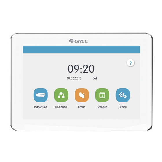
Page 12: Main Page Display And Buttons
Multi-VRF Centralized Controller 2.1 Main Page Display and Buttons Name Instructions When indoor unit is on, the current operation mode will be displayed: ① Operation mode Auto Cooling Heating Floor heating Space heating 3D heating ② Current page The total pages of the controlled indoor unit and the current page. ③... -
Page 13: Buttons Working Instructions
Multi-VRF Centralized Controller 2.3 Buttons Working Instructions The centralized controller uses a capacitive touch screen so that user can operate the units by just touching the screen. Buttons on the screen are presented in the following ways: (1) Icon Icon button can be operated directly. See section 2.2 for more details. (2) Icon + Text According to the meaning of Text, turn on or off or select a certain function, or enter a certain page. -
Page 14: Functions Description
Multi-VRF Centralized Controller Fig.2.2 Zone Buttons on the Group Control Page 3 FUNCTIONS DESCRIPTION 3.1 All ON/OFF On the home page, press the “All OFF” button to turn off all indoor units. Press the “All ON” button to turn on all indoor units. Then indoor units will work according to memory. - Page 15 Multi-VRF Centralized Controller (1) General Control Parameters 1) On/off Press the on/off button to turn unit on or off. When unit is turned off, mode, temperature, fan speed and swing can’t be set. 2) Mode setting Press the Mode buttons to set unit’s operation mode. Modes for indoor units of different series are not all the same.
-
Page 16: Water /Floor Control
Multi-VRF Centralized Controller malfunctions. (2) Advanced Control Parameters Press Advance Button to enter the advance page. Press icon buttons to turn on or off the corresponding function. Fig.3.2 Advance Page 1) Functions of Sleep, Quiet, E-Heater, Absence and Rapid can only be effective when unit is turned on. - Page 17 Multi-VRF Centralized Controller Notes: (1)When there is only one function can be selected (water or floor), it can only display the water heating or floor heating function interface, and cannot be switched to another interface; (2)Only when it is connected to hot water generator, water heating and floor heating functions are applicable, the interface can be switched and displaced according to the above instructions;...
- Page 18 Multi-VRF Centralized Controller will start up the unit in advance according to the actual water temperature, and will decide the on and off of water tank or hot water generator according to the temperature difference between actual water temperature and the setting water temperature. The water tank or hot water generator will close down the unit 1~4 hours later after the preset time.
- Page 19 Multi-VRF Centralized Controller Auto function: the setting temperature of water heating will be automatically provided by water heater according to the outdoor ambient temperature, there is no need to set by the user, and the water temperature cannot be adjusted via buttons.
- Page 20 Multi-VRF Centralized Controller (1)On/off Press the on/off button to trun unit on or off. When the unit is off, the mode and temperature cannot be set. (2)Temperature Setting Press the button of “Current Temp” to view the current water yielding temperature. After pressing “Setting Temp”, the temperature value can be adjusted by pressing up and down buttons, the temperature value will increase or decrease by every pressing the button for once.
-
Page 21: E-Control Function
Multi-VRF Centralized Controller 3.4 e-Control Function On the home page, pressing e-Control button can enter the page of e-Control. e-Control includes 5 short-cut modes (Sleep, Bath, Home, Leaving and Stay out) and 3 DIY modes. User may reset the functions of different modes according to actual needs. Fig.3.5 e-Control Page (1) Turn on e-Control Pressing the zone button can turn on the selected short-cut mode. -
Page 22: Group Control
Multi-VRF Centralized Controller Note: For a same indoor unit, different modes can be set at the same time. In this case, indoor unit will work according to the latest energized mode. (4) Restore default settings On the edition page, press the button to restore the ex-factory default settings. -
Page 23: Schedule Management
Multi-VRF Centralized Controller Press button to send out the group control order. (2) Edit group Press to enter the page of group editing. Use can set the group name and add indoor units to the group. Press to save the setting. Note: 1 set of indoor unit can be set in up to 5 groups (1) Add group Press... - Page 24 Multi-VRF Centralized Controller When schedule is open, centralized controller will send out the control order automatically according to the time and parameters set by the schedule. (2) Edit schedule Press to enter the page of schedule editing. Fig.3.8 Page of Schedule Editing Press to save the schedule setting.
-
Page 25: Local Setting
Multi-VRF Centralized Controller Press button to enter the setting page of schedule exception. The setting method of the control parameters of schedule exception are the same with the setting method of the parameters of ordinary schedule. Press to save the set parameters. - Page 26 Multi-VRF Centralized Controller Press the button to switch to the setting options of the current unit. Select the needed option at the left side column. Sliding up and down can turn over the page. Set the corresponding content at the right side. Local setting includes: Sound, language, temperature unit, background, mutual exclusion Press the button to select one kind of setting.
-
Page 27: Engineering Setting
Multi-VRF Centralized Controller restore the ex-factory setting for centralized controller. 2) After debugging for the centralized controller is finished, connect in to the network. If connect the centralized controller to the network during debugging process, it needs to restore the defaulted ex-factory setting. 3.8 Engineering Setting On the home page, press setting to enter into setting interface. -
Page 28: Operation Notice
Multi-VRF Centralized Controller (1)Name: can input number or letter (it should not be over 10 letters) (2)Icon: press to select the preset icon. (3)Engineering No.: press , it can be set to be 1-255. (4)Press button to successfully save the setting. Then the indoor unit list in the home page will display the new name and icon of indoor units. - Page 29 GREE ELECTRIC APPLIANCES, INC. OF ZHUHAI Add: West Jinji Rd, Qianshan, Zhuhai, Guangdong, China, 519070 Tel: (+86-756) 8522218 Fax: (+86-756) 8669426 E-mail: gree@gree.com.cn www.gree.com...
Need help?
Do you have a question about the CE53-24/F(C) and is the answer not in the manual?
Questions and answers