Table of Contents
Advertisement
Quick Links
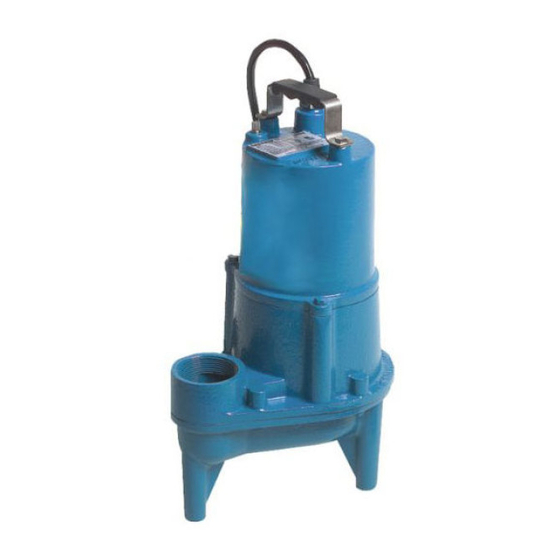
Submersible Effl uent & Sewage Ejector
IMPORTANT!
Read all instructions in this manual before operating pump.
As a result of Crane Pumps & Systems, Inc., constant product improvement program,
product changes may occur. As such Crane Pumps & Systems reserves the right to
change product without prior written notifi cation.
A Crane Co. Company
420 Third Street
Piqua, Ohio 45356
Phone: (937) 778-8947
Fax: (937) 773-7157
www.cranepumps.com
Manual Index
BARNES
INSTALLATION MANUAL
Series: SEV412
1/2 HP, 3450 RPM, 60 Hz.
83 West Drive, Bramton
Ontario, Canada L6T 2J6
Phone: (905) 457-6223
Fax: (905) 457-2650
®
EHV412
Form No. 102075-Rev. AA
Advertisement
Table of Contents

Related Manuals for Crane BARNES SEV412 Series


Summary of Contents for Crane BARNES SEV412 Series
- Page 1 Read all instructions in this manual before operating pump. As a result of Crane Pumps & Systems, Inc., constant product improvement program, product changes may occur. As such Crane Pumps & Systems reserves the right to change product without prior written notifi cation.
-
Page 2: Safety First
Other brand and product names are trademarks or registered trademarks of their respective holders. ® Barnes is a registered trademark of Crane Pumps & Systems, Inc. 1998, 2000, 2001, 2002, 2003, 8/05, 2/06, 9/06 Alteration Rights Reserved... - Page 3 PUMP SPECIFICATIONS - SEV412 SERIES: DISCHARGE ....... 2” NPT, Female, Vertical MOTOR: Design ..... Oil Filled LIQUID TEMPERATURE ..77°F (25°C) Continuous Insulation ..Class B MOTOR HOUSING ..... Cast Iron SINGLE PHASE ....Permanent Split Capacitor (PSC) PUMP BODY ....... Cast Iron Includes Thermal Overload IMPELLER: Protection in motor...
- Page 4 PUMP SPECIFICATIONS - EHV412 SERIES: DISCHARGE ....... 2” NPT, Female, Vertical LOWER BEARING: LIQUID TEMPERATURE ..77°F (25°C) Continuous Design ..... Single Row, Ball, Oil Lubricated MOTOR HOUSING ..... Cast Iron Load ....Radial & Thrust PUMP BODY ....... Cast Iron MOTOR: Design .....
-
Page 5: Section B: General Information
Figure 2 shows a typical installation for any submersible & Systems, Inc., Service Department in Piqua, Ohio, pump using a level control mounted to the discharge piping telephone (937) 778-8947 or Crane Pumps & Systems with a piggy-back plug. Canada, Inc., Bramton, Ontario, (905) 457-6223. - Page 6 6.) Figure 3 shows a typical connection for pumps with the wide angle fl oat and piggy-back plug, for manual and automatic operations. Automatic Manual FIGURE 3 Automatic - Plug fl oat cord into GFI outlet, then plug pump cord into fl oat cord. Manual - Plug pump cord directly into GFI outlet.
-
Page 7: Section D: Service And Repair
C-4.2) Overload Protection: D-1.1) Checking Oil: Single Phase - The type of in-winding overload protector To check oil, set unit upright. Remove pipe plug. With a used is referred to as an inherent overheating protector fl ashlight, visually inspect the oil in the motor housing to and operates on the combined effect of temperature and make sure it is clean, clear and that the oil level is above current. -
Page 8: Shaft Seal Service
Motor & Lower Motor TABLE 1 - COOLING OIL - Dielectric Housing SUPPLIER GRADE Seal Pusher Enerpar SE100 Conoco Pale Paraffi n 22 Mobile D.T.E. Oil Light G & G Oil Circulating 22 Imperial Oil Voltesso-35 Shell Canada Transformer-10 Bullet Rotating Member Texaco Diala-Oil-AX... - Page 9 SECTION: F REPLACEMENT PARTS F-1 ORDERING REPLACEMENT PARTS: When ordering replacement parts, ALWAYS furnish the following information: 1. Pump Part Number 2. Pump model number 3. Pump date code F-2 Part Number: The part number consists of a six (6) digit number, which appears in the catalog.
- Page 10 SEV412 Testing is performed with water specifi c gravity of 1.0 @ 68˚F (20˚C), other fl uids may vary performance EHV412...
-
Page 11: Troubleshooting
TROUBLE SHOOTING CAUTION ! Always disconnect the pump from the electrical power source before handling. If the system fails to operate properly, carefully read instructions and perform maintenance recommendations. If operating problems persist, the following chart may be of assistance in identifying and correcting them: MATCH “CAUSE”... -
Page 12: Parts List
FIGURE 8 PARTS LIST ITEM DESCRIPTION PART NO. Shaft Seal 128260 Cord Set Assy, 20 Ft. 099260XA Vertical Float, 20 Ft. Cord - VF Series 103476 Vertical Float, 20 Ft. Cord - VFT Series 103475A Wide Angle Float, Piggy-Back Plug 101758XA Diapragm Switch, 20 Ft. - Page 13 Limited 24 Month Warranty Crane Pumps & Systems warrants that products of our manufacture will be free of defects in material and workmanship under normal use and service for twenty-four (24) months after manufacture date, when installed and maintained in accordance with our instructions.This warranty gives you speci• c legal rights, and there may also be other rights which vary from state to state.
-
Page 14: Returned Goods
Crane Pumps & Systems, Inc. Distributor. RETURNED GOODS RETURN OF MERCHANDISE REQUIRES A “RETURNED GOODS AUTHORIZATION”. CONTACT YOUR LOCAL CRANE PUMPS & SYSTEMS, INC. DISTRIBUTOR. Products Returned Must Be Cleaned, Sanitized, Or Decontaminated As Necessary Prior To Shipment, To Insure That Employees Will Not Be Exposed To Health Hazards In Handling Said Material.
Need help?
Do you have a question about the BARNES SEV412 Series and is the answer not in the manual?
Questions and answers