Table of Contents
Advertisement
Quick Links
INSTALLATION and OPERATION MANUAL
IMPORTANT:
Read all instructions in this manual before operating pump.
As a result of Crane Pumps & Systems, Inc., constant product improvement program, product
changes may occur. As such Crane Pumps & Systems, Inc., reserves the right to change product
without prior written notification.
PUMPS & SYSTEMS
A Crane Co. Company
420 Third Street/P.O. Box 603
Piqua, Ohio 45356-0603
Phone: (937) 778-8947
Fax: (937) 773-7157
www.cranepumps.com
Manual Index
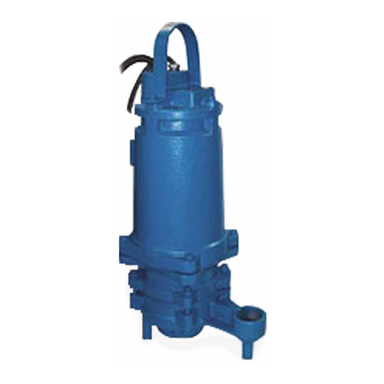
BARNES
Submersible Grinder Pump
83 West Drive, Brampton
Ontario, Canada L6T 2J6
Phone: (905) 457-6223
Fax: (905) 457-2650
®
Series: SGV 2 HP
3450 RPM
Series: SGV 3, 5, 7.5HP
3450 RPM
SUPERSEDED
Some parts may NOT
be available
Form No. 084843-Rev. F
Advertisement
Table of Contents

Related Manuals for Crane BARNES SGV 2 HP Series


Summary of Contents for Crane BARNES SGV 2 HP Series
- Page 1 Read all instructions in this manual before operating pump. As a result of Crane Pumps & Systems, Inc., constant product improvement program, product changes may occur. As such Crane Pumps & Systems, Inc., reserves the right to change product without prior written notification.
-
Page 2: Table Of Contents
TABLE OF CONTENTS USER GUIDE ........................3 WARNINGS AND SAFETY PRECAUTIONS................ 4 A-1. PUMP SPECIFICATIONS- 2HP ..................5 A-2. PUMP SPECIFICATIONS- 3, 5, 7.5HP ................6 B. GENERAL INFORMATION ....................7 C. INSTALLATION ........................7 - 8 D. SERVICE and REPAIR......................8 - 15 TROUBLESHOOTING...................... -
Page 3: User Guide
USER GUIDE Congratulations on your purchase of a The grinder pump generates sufficient B a r ne s UltraG RI N D g ri n de r pu mp pressure to pump this slurry from your home system. With proper care and by following a to the wastewater plant. -
Page 4: Warnings And Safety Precautions
SAFETY FIRST! PLEASE READ THIS BEFORE INSTALLING OR OPERATING PUMP. GENERAL 1. Most accidents can be avoided by using COMMON SENSE. 2. Read this operation and maintenance instruction manual. 3. Do not wear loose clothing that may become entangled in the impeller or other moving parts. 4. -
Page 5: A-1. Pump Specifications- 2Hp
SECTION: A-1 - PUMP SPECIFICATIONS- SERIES: SGV 2 HP DISCHARGE: 1-1/4" (32mm) NPT, Vertical UPPER BEARING: LIQUID TEMPERATURE: 160°F (71°C) Intermittent Design: Single row, ball VOLUTE: Cast iron ASTM A-48, Class 30. Lubrication: MOTOR HOUSING: Cast iron ASTM A-48, Class 30. Load: Radial SEAL PLATE:... -
Page 6: A-2. Pump Specifications- 3, 5, 7.5Hp
SECTION: A- 2 - PUMP SPECIFICATIONS- SERIES: SGV 3, 5 & 7.5 HP DISCHARGE: 2" (51mm) NPT, Vertical UPPER BEARING: LIQUID TEMPERATURE: 160°F (71°C) Intermittent Design: Single row, ball VOLUTE: Cast iron ASTM A-48, Class 30. Lubrication: MOTOR HOUSING: Cast iron ASTM A-48, Class 30. Load: Radial SEAL PLATE:... -
Page 7: General Information
Department in Piqua, Ohio, telephone (937) 778-8947 or pumps on the market today. Barnes Pumps are products Crane Pumps & Systems Canada, in Brampton, Ontario, engineered and manufactured of high quality components. (905) 457-6223. Over one hundred years of pump building experience along... -
Page 8: Service And Repair
C-3) Electrical Connections: above situations may induce a false signal in the moisture detecting circuit. If none of the above tests prove conclusive, the pump(s) should be pulled and the source WARNING ! - All model pumps and control of the failure identified and repaired. IF A MOISTURE panels must be properly grounded per The DE T E C T H A S... - Page 9 D-1) Lubrication: Seal Chamber- Set unit on its side with fill plug (36) Anytime the pump is removed from operation, the cooling downward, (located on intermediate coupling 6), remove oil in the motor housing (10) should be checked visually for plug (36) and drain all oil from seal chamber.
- Page 10 MOTOR END MOTOR END Seal Plate (19) (INBOARD END) (INBOARD END) Intermediate (6) Stationary (21a) Retaining Ring (5d) SEAL ASSEMBLY (21) Spring (5c) SEAL Rotating Spring (21c) Member (21b) ASSEMBLY (5) Rotating Member (5b) Retaining Ring (21d) Stationary (5a) PUMP END PUMP END (OUTBOARD END) (OUTBOARD END)
- Page 11 MOTOR & Examine all seal parts and especially contact faces. Inspect STATIONARY ROTATING MEMBER INTERMEDIATE (21a) & (5a) (21b) & (5b) seal for signs of wear such as uneven wear pattern on COUPLING stationary members, chips and scratches on either seal face. DO NOT interchange seal components, replace the entire shaft seal (21).
- Page 12 If replacement is required, remove seal parts, rotating threads. Lightly oil (DO NOT use grease) shaft, bullet and member (5b), spring (5c) and retaining ring (5d) from shaft. inner surface of bellows on rotating member (5b). See Figure Examine all seal parts and especially contact faces. Inspect 7.
- Page 13 POWER SINGLE PHASE, 200-230 VOLT AC Large Cable Power Cable Motor Lead Number L1 L2 L3 Green (Ground) Green White 5 (Common) Black 4 (Run) 8 (Start) T4 T8 T5 MOTOR LEADS POWER Large Cable THREE PHASE, 200 & 575 VOLT AC G L1 L2 L3 Power Cable Motor Lead Number...
- Page 14 CONTROL CONTROL Small Cable Small Cable Temperature Moisture Temperature Sensor Sensor Sensor Leads Leads Leads THERMOSTAT THERMOSTAT MOISTURE & TEMPERATURE CABLE CONNECTION TEMPERATURE SENSOR CABLE CONNECTION (Five wire cable replaces standard two wire cable) (Standard two wire cable) Color Lead Number Color Lead Number Black...
- Page 15 D-4.4) Cable Assembly: Remove gland nuts (15b) & (16b), friction rings (15c) & (16c) and grommets (15d) & (16d) from motor housing (10) on 2HP and from cover plate (13) on 3,5,7.5HP, inspect and replace if required. See Fig. 9. Power Cable- To reassemble, insert one friction ring (15c), grommet (15d), one friction ring (15c) and gland nut (15b) into cover plate (13).
-
Page 16: Troubleshooting
TROUBLESHOOTING CAUTION ! Always disconnect the pump from the electrical power source before handling. If the system fails to operate properly, carefully read instructions and perform maintenance recommendations. If operating problems persist, the following chart may be of assistance in identifying and correcting them: MATCH "CAUSE"... -
Page 17: Replacement Parts
SECTION F: REPLACEMENT PARTS E-1 ORDERING REPLACEMENT PARTS: When ordering replacement parts, ALWAYS furnish the following information: 1. Pump serial number and date code. (E-4) 2. Pump model number. (E-3) 3. Pump part number. (E-2) 4. Part description. 5. Item part number. 6. -
Page 18: Cross-Section 2 Hp Sgv (Fig. 10)
2HP - SGV - SERIES Fig. 10... -
Page 19: Exploded View 2 Hp Sgv (Fig. 11)
2HP - SGV - SERIES Fig. 11... -
Page 20: Parts List--2Hp Sgv
2HP - SGV - SERIES PARTS KITS Seal Repair Kit .P/N-085222 (†) 5,8,15d,16d,20,21,29,34,35. Overhaul Kit ..P/N-085221 (◊) 2,3,5,7,8,9,15d,16d,17,20,21,33,30,34,35,47. Seal Tool Kit Outer....T/L-21360 Inner....T/L-21357-SGV Cutter Kit ..P/N-085226 (‡) 11,25,27,30,32,33,34,35. Pressure Gauge Kit ..P/N-085343 PARTS LIST ITEM DESCRIPTION PART No. Motor - 2Hp, 230V, 1Ph 075876 2Hp, 200V, 3Ph 067571... - Page 21 2HP - SGV - SERIES Cord Set (Control) MOIST. & TEMP. CSA Units Non-CSA Standard Length 15 FT. 090066 079031 25 FT. 090066XB 079031XB 30 FT. 090066XC 079031XC 40 FT. 090066XE 079031XE 50 FT. 090066XF 079031XF 75 FT. 090066XJ 079031XJ 100 FT.
- Page 22 2HP - SGV - SERIES Terminal Connector (Optional Moisture Sensor) 026880 Terminal Connector (Temp Only Std) 026880 Machine Screw (Optional Moisture Sensor) 038156 #6-32 x 3/8" Lg Stainless ◊ Wire Connector 016405 Hex Plug 2" NPT, Cast Iron 084534...
-
Page 23: Cross-Section 3,5,7.5 Hp Sgv (Fig. 12)
3, 5 & 7.5HP - SGV - SERIES 16 15 30 11 ±.020 Fig. 12... -
Page 24: Exploded View 3,5,7.5 Hp Sgv (Fig. 13)
3, 5 & 7.5HP - SGV - SERIES Fig. 13... -
Page 25: Parts List--3, 5,7.5Hp Sgv
3, 5 & 7.5HP - SGV - SERIES PARTS KITS Seal Repair Kit .P/N-085223 (†) 5,8,14,15d,16d,20,21,34,35. Overhaul Kit ..P/N-085224 (◊) 2,3,5,7,8,9,14,15d,16d,20,21,34,35. Seal Tool Kit Cutter Kit ..P/N-085225 (‡) 11,25,27,30,32,33,34,35. PARTS LIST ITEM QTY. DESCRIPTION PART No. Motor - 3HP, 200V, 1Ph 085598 3Hp, 230V, 1Ph 085598... - Page 26 3, 5 & 7.5HP - SGV - SERIES Standard Length 25 FT. 093285XB 30 FT. 093285XC 40 FT. 093285XE 50 FT. 093285XF 75 FT. 093285XJ 100 FT. 093285XL 125 FT. 093285XP 150 FT. 093285XS 175 FT. 093285XV 200 FT. 093285XY * Cable (Not Sold Separately) * Gland Nut...
- Page 27 3, 5 & 7.5HP - SGV - SERIES 6.38 Dia. 084214TA 6.25 Dia. (STD. for 5HP) 084214TB 6.12 Dia. 084214TC 6.00 Dia. 084214TD 5.88 Dia. 084214TE 5.75 Dia. 084214TF 5.62 Dia. 084214TG 5.50 Dia. 084214TH 5.38 Dia. 084214TJ 5.25 Dia. 084214TK 5.12 Dia.
-
Page 28: Electrical Data
MODEL HP VOLTS PH NEMA FULL LOCKED CORD CORD CORD EMERSON (Nom) START LOAD ROTOR SIZE TYPE O.D. WINDING WINDING CODE AMPS AMPS RESISTANCE RESISTANCE MAIN--START MAIN--START SGV2002L 3450 17.0 53.0 10/4 0.745 0.98 -- 7.29 --------- SGV2022L 3450 16.0 46.0 10/4 0.745... -
Page 29: Suspended Systems
SUSPENDED PUMP SYSTEMS Remove four hex nuts (30) and lockwashers (11) from volute (28) (see Figure 11) and remove volute (28) and rotate 90° clockwise. See Figure 14, so that the discharge is 90° from tapped holes in motor housing (10). Replace hex nuts (30) and lockwashers (11) and tighten. -
Page 30: Moveable For Basin Package
MOVEABLE ASSEMBLY For "C" Channel Basin Package PARTS LIST For 079156*, 2HP Grinder ITEM QTY. DESCRIPTION PART No. Lower Pump Bracket, Stainless 075944 Pipe, Stainless 1.25 NPT x 14" Lg. 075589 Ball Check Valve , Cast Iron 1.25 NPT 077881 Close Nipple, Stainless 1.25 NPT 075476... - Page 31 MOVEABLE ASSEMBLY For "C" Channel Basin Package PARTS LIST For 079157*, 3,5 & 7.5HP Grinder ITEM QTY. DESCRIPTION PART No. Lower Pump Bracket, Stainless 078840 Pipe, Stainless 2 NPT x 3.5" Lg. 083690 Ball Check Valve Cast Iron 2 NPT 077882 Close Nipple, Stainless 2 NPT...
- Page 32 NOTES:...
-
Page 33: Warranty Information
Complete the Warranty Registration Form and returned to Crane Pumps & Systems, Inc. Warranty Service Group IMPORTANT! If you have a claim under the provision of the warranty, contact your local Crane Pumps & Systems, Inc. Distributor. RETURNED GOODS RETURN OF MERCHANDISE REQUIRES A "RETURNED GOODS AUTHORIZATION". - Page 34 No rights extended under this warranty shall be assigned to any other person, whether by operation of law or otherwise, without our prior written approval. PUMPS & SYSTEMS A Crane Co. Company 420 Third Street/P.O. Box 603 83 West Drive, Brampton...
- Page 35 START UP / WARRANTY REGISTRATION FORM This report is designed to provide assurance that customer service and a quality product are the number one priority with Barnes® Pumps, Inc. Please answer the following questions completely and accurately as possible. When complete, mail this form to: Parts &...
- Page 36 BASIN INFORMATION (Cont.) Method of Cable Entry into Basin: Direct Burial Cable W/Cord Grips Conduit Coupling Cable Sizes(s) from Control Panel to Basin: (Example: 10/4 power cable and Two 18/4 Control Cables) Valve at Sewer Main: Check Valve Manual shut Off Valve JUNCTION BOX INFORMATION Is Junction Box Dry: Are All Cord Grips Tight:...
- Page 37 ELECTRICAL CHECK (cont.) Meg-Ohm Insulation Check Taken at Control Panel with Power Off: Red/Ground Black/Ground White/Ground NOTE: Readings of 5 and higher are acceptable. “0” Reading indicates A Dead Short. PERFORMANCE CHECK NOTE: With Pump Power OFF fill basin with a minimum of thirty-two inches of water. NEXT: Turn the power ON.
- Page 38 FOLD HERE AND TAPE, DO NOT STAPLE PLACE STAMP HERE CRANE PUMPS & SYSTEMS, INC. WARRANTY SERVICE GROUP 420 THIRD STREET P.O. BOX 603 PIQUA, OHIO 45356-0603 - U.S.A.
Need help?
Do you have a question about the BARNES SGV 2 HP Series and is the answer not in the manual?
Questions and answers