Table of Contents
Advertisement
Quick Links
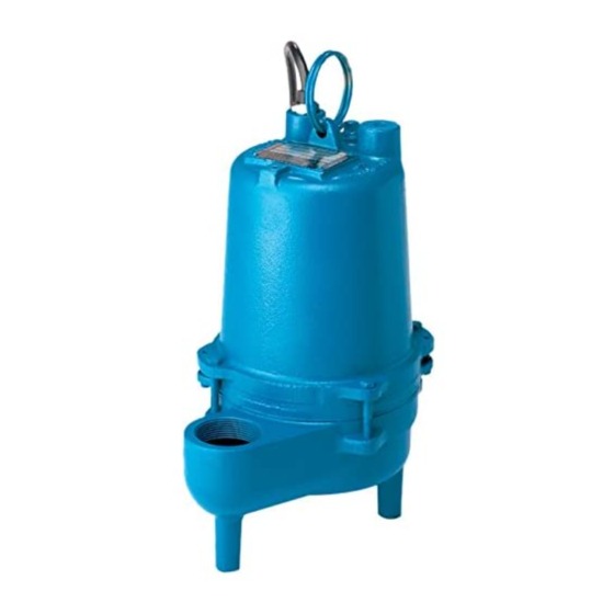
Submersible Fountain Pumps
IMPORTANT!
Read all instructions in this manual before operating pump.
As a result of Crane Pumps & Systems, Inc., constant product improvement program,
product changes may occur. As such Crane Pumps & Systems reserves the right to
change product without prior written notifi cation.
A Crane Co. Company
420 Third Street
Piqua, Ohio 45356
Phone: (937) 778-8947
Fax: (937) 773-7157
www.cranepumps.com
Manual Index
BARNES
BARNES
INSTALLATION MANUAL
Series: SF411, .4HP
83 West Drive, Bramton
Ontario, Canada L6T 2J6
Phone: (905) 457-6223
Fax: (905) 457-2650
®
1750 RPM, 60 Hz.
Form No. 108120-Rev. J
Advertisement
Table of Contents

Related Manuals for Crane Barnes SF411 Series


Summary of Contents for Crane Barnes SF411 Series
- Page 1 Read all instructions in this manual before operating pump. As a result of Crane Pumps & Systems, Inc., constant product improvement program, product changes may occur. As such Crane Pumps & Systems reserves the right to change product without prior written notifi cation.
-
Page 2: Table Of Contents
PRESSURE GAUGE KIT (see parts list) Other brand and product names are trademarks or registered trademarks of their respective holders. ® Barnes is a registered trademark of Crane Pumps & Systems, Inc. 2000, 2002, 01/04, 10/05, 4/06, 9/06 Alteration Rights Reserved... -
Page 3: Warnings And Safety Precautions
Crane Pumps & Systems, Inc. is not responsible for WARNING ! Do not pump hazardous materials losses, injury, or death resulting from a failure to observe (fl... -
Page 4: Pump Specifications
PUMP SPECIFICATIONS SERIES: DISCHARGE ....... 2” NPT, Female, Vertical CORD ENTRY ..... 15 Ft. (5m) Quick disconnect cord LIQUID TEMP ..... 77°F (25°C) Continuous with plug on 115 volt, pressure MOTOR HOUSING ..... Cast Iron ASTM A-48, Class 30 gromment for sealing and strain relief. VOLUTE ...... -
Page 5: General Information (Receiving, Storage, Service Centers)
& Systems, Inc., Service Department in Piqua, Ohio, with a piggy-back plug. telephone (937) 778-8947 or Crane Pumps & Systems Canada, Inc., Bramton, Ontario, (905) 457-6223. SECTION C: INSTALLATION C-1) Location: These pumping units are self-contained and are recommended for use in a sump or basin. -
Page 6: (Overload Protection, Wire Size)
Automatic Manual FIGURE 3 Automatic - Plug fl oat cord into GFI outlet, then plug pump cord into fl oat cord. Manual - Plug pump cord directly into GFI outlet. C-4) Electrical Connections: C-4.1) Power Cable: The cord assembly mounted to the pump must not be modifi... -
Page 7: (Electrical Data)
MODEL NO VOLT/ NEMA FULL LOCKED CORD CORD CORD WINDING (Nom) START LOAD ROTOR SIZE TYPE RESISTANCE CODE AMPS AMPS inch (mm) MAIN - START SF411 115/1 1750 12.0 19.0 14/3 SJTOW 0.375 (9.5) 2.14 - 30.5 Winding Resistance ± 5%. Pump rated for operation at ±... -
Page 8: (Replacing Oil, Pressure Test, Impeller & Volute, Motor, Bearing & Cable Service) (Fig. 4, 5, 6, 7, 8)
Use a soap solution around the sealed areas and inspect F-1.3 Replacing Oil in Motor Housing: Drain all oil from motor housing and dispose of properly. joints for “air bubbles”. If, after fi ve minutes, the pressure Refi ll with 58 ounces of new cooling oil as per Table 1. An is still holding constant, and no “bubbles”... - Page 9 Bearings - Disassemble motor as per section F-3.1. Remove snap ring (6) with snap ring pliers and pull motor (1) and lower bearing (4) straight off of seal plate (2). Inspect all parts for signs of wear and replace as needed. CAUTION! Handle seal parts with extreme care.
-
Page 10: (Shaft Seal Service) (Fig. 7, 9)
F-4) Shaft Seal Service F-4.3) Replacing Exclusion Seal: The exclusion seal (16), helps to keep debris away from F-4.1) Dissassembly and Inspection: Disassemble pump motor as per section F-3.1. Inspect the shaft seal where it could cause damage. The exclusion seal for signs of wear such as uneven wear pattern on the seal should be replaced whenever the shaft seal is stationary member or chips and scratches on either sealing... -
Page 11: Trouble Shooting
TROUBLE SHOOTING CAUTION ! Always disconnect the pump from the electrical power source before handling. If the system fails to operate properly, carefully read instructions and perform maintenance recommendations. If operating problems persist, the following chart may be of assistance in identifying and correcting them: MATCH “CAUSE”... -
Page 12: Cross-Section (Fig. 10)
FIGURE 10... -
Page 13: Exploded View (Fig. 11)
FIGURE 11... -
Page 14: Parts List
PARTS KITS Overhaul Kit..... P/N: 085201 (†) 3,4,6,13,16,19,24 Seal Kit......P/N: 085202 (◊) 3,13,16,19 PRESSURE GAUGE KIT.. P/N: 085343 PARTS LIST ITEM PART No. DESCRIPTION 102260 Motor & Sleeve, SF411 093063 Seal Plate Cast Iron 068988 ◊† Shaft Seal, (Standard) Carbon/Ceramic/Buna-N 068988SB Tungsten/Tungsten/Buna-N... -
Page 15: Performance Curve
Testing is performed with water specifi c gravity of 1.0 @ 68˚F (20˚C), other fl uids may vary performance Notes... -
Page 16: Return Goods Policy
RETURNED GOODS RETURN OF MERCHANDISE REQUIRES A “RETURNED GOODS AUTHORIZATION”. CONTACT YOUR LOCAL CRANE PUMPS & SYSTEMS, INC. DISTRIBUTOR. Products Returned Must Be Cleaned, Sanitized, Or Decontaminated As Necessary Prior To Shipment, To Insure That Employees Will Not Be Exposed To Health Hazards In Handling Said Material. -
Page 17: Start Up Report
This form is designed to provide assurance that customer service and a quality product are the number one priority with Crane Pumps & Systems, Inc (CP&S). Please fi ll out the following questions as completely and accurate as possible. When complete, mail this form to: In U.S.A Send To:... - Page 18 CP&S control panel part no. and brand Number of pumps operated by control panel NOTE: At no time should holes be made in top of control panel, unless proper sealing devices are utilized. Control panel manufactured by others Company name Model number Short circuit protection Type...
-
Page 19: Warranty Registration
Your product is covered by the enclosed Warranty. Complete the Warranty Registration Form and return to Crane Pumps & Systems, Inc. Warranty Service Group If you have a claim under the provision of the warranty, contact your local Crane Pumps & Systems, Inc. Distributor. - Page 20 FOLD HERE AND TAPE, DO NOT STAPLE PLACE STAMP HERE CRANE PUMPS & SYSTEMS, INC. WARRANTY SERVICE GROUP 420 THIRD STREET PIQUA, OHIO 45356 - U.S.A.
Need help?
Do you have a question about the Barnes SF411 Series and is the answer not in the manual?
Questions and answers