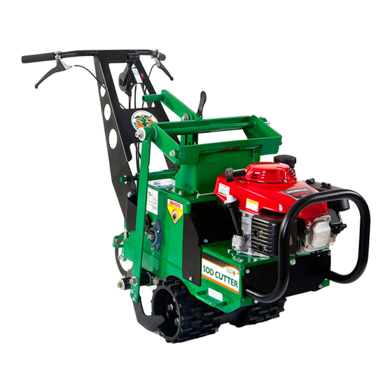
Billy Goat SC181H Operator's Manual
Hide thumbs
Also See for SC181H:
- Owner's manual (37 pages) ,
- Owner's manual (37 pages) ,
- Operator's manual (32 pages)
Table of Contents
Advertisement
Quick Links
Advertisement
Table of Contents

Summary of Contents for Billy Goat SC181H
- Page 1 373506...
-
Page 2: Table Of Contents
Table of Contents: Intended Use................. 3 California Proposition 65............. 3 Initial Setup................3 Setup Checklist..............3 Uncrating The Unit............3 Features and Controls............3 Unit Decals............... 3 Drive Controls..............5 Blade Engage Lever............5 Engine Stop Switch............5 Choke-Throttle Lever............5 Blade Height Adjuster............5 Free Wheel Lever.............6 Operation................ -
Page 3: Intended Use
The decals shown in Figure 1 were installed on your new are trained in general machine use and safety. Billy Goat 18" Sod Cutter. If any decals are damaged or missing, replace them before operation. Use the images and corresponding part numbers when ordering replacement WARNING labels. - Page 4 373501 - Decal, Blade Arm 373505 - Decal, Service Instructions 373503 - Decal, Height Adjuster 400424 - Decal, Warning Sharp 373504 - Decal, Drive Enable 830502 - Decal, Oil Chain 371501 - Decal, Caster Left billygoat.com...
-
Page 5: Drive Controls
Engine Stop Switch 371504 - Decal, Caster Right The engine stop switch is conveniently located on right of the operator console (D, Figure 2). To start the unit, move the engine stop switch to the "ON" position and pull the recoil starter on the engine. ... -
Page 6: Free Wheel Lever
Free Wheel Lever The free wheel lever (B, Figure 4) is located next to the blade height adjuster. Pull the lever out to disengage the drive and enable free-wheel motion. Free-wheel motion allows you to transport the unit, pushing and/or pulling by hand as necessary. -
Page 7: Operation
Operation ground conditions allow, increase or decrease the ground speed of the unit. To gradually increase speed, gradually depress the lever. The unit operates at maximum speed Before Operation with the lever fully depressed. The unit operates at minimum speed with the lever minimally depressed. As with all mechanical tools, use reasonable care during operation. -
Page 8: Belt Maintenance
6. Slip the damaged or worn drive belt from around the Maintenance Each Use transmission pulley (D). From a position at the front of the Operation unit, gently pull the belt, navigating it around the idler arm Replace engine (B). air filter. -
Page 9: Blade Maintenance
1. Park the unit on a flat, level surface. Turn off the engine Note: The blade wears faster when operating in dry and/or and disconnect the spark plug wire. sandy conditions. Under these conditions, it will need to be 2. To adjust cable tension, adjust the barrel length (A, replaced more frequently. -
Page 10: Specifications
Specifications DIMENSIONS Overall Length 60" (152 cm) Overall Width 26.5" (67.3 cm) Overall Height 38.5" (97.8 cm) Total Unit Weight* (SC181H, 395 lb (179.2 kg) SC181HG) Total Unit Weight* (SC181K, 397 lb (180.1 kg) SC181KG) Maximum Operating Slope 20° ENGINE...


Need help?
Do you have a question about the SC181H and is the answer not in the manual?
Questions and answers