Billy Goat SC181H Owner's Manual
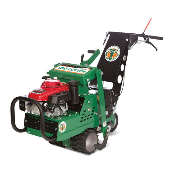
Sod cutter
Hide thumbs
Also See for SC181H:
- Owner's manual (37 pages) ,
- Operator's manual (32 pages) ,
- Operator's manual (11 pages)

Related Manuals for Billy Goat SC181H


Summary of Contents for Billy Goat SC181H
- Page 1 SC181H Owner’s Manual Sod Cutter Owner’s Manual SC181H, SC181HG Beginning Serial #: 110116001 Original Instructions IMPORTANT- READ CAREFULLY BEFORE USE AND KEEP FOR FUTURE REFERENCE Part No. 373506 373506_B_HI...
-
Page 2: Table Of Contents
About this Manual Thank you for purchasing a BILLY GOAT® Sod Cutter. Your new machine has been carefully designed and manufactured to provide years of reliable and productive service. This manual provides complete operating and maintenance instructions that will help to maintain your machine in top running order. -
Page 3: Specifications, Intended Use, And Safety
Specifications SC181H SC181HG Engine: HP 5.5 HP (4.1 kw) 5.5 HP (4.1 kw) Engine: Model GXV160UH2N1AH GXV160UH2N1AH Engine: Type Honda Honda Engine: Fuel Capacity 1.6 qt. (1.5 L) 1.6 qt. (1.5 L) Engine: Oil Capacity 0.69 qt. (0.65 L) 0.69 qt. (0.65 L) Total Unit Weight 395 lb. -
Page 4: Instruction Labels
Instruction Labels The labels shown below were installed on your BILLY GOAT® Sod Cutter. If any labels are damaged or missing, replace them before operating this equipment. Item numbers from the Illustrated Parts List and part numbers are provided for convenience in ordering replacement labels. The correct position for each label may be determined by referring to the Figure and Item numbers shown. -
Page 5: Uncrating Instructions
Uncrating Instructions Your Billy Goat Sod Cutter is shipped from the factory in one crate, completely assembled. Be Sure To: • Read all safety instructions before assembling unit. • Take caution when removing the unit from the box. • Put oil in engine before starting. -
Page 6: Operator Controls
Operator Controls Drive Control: The ground drive controls are located on each handlebar of the machine. The right side lever control moves the machine forward at varying speeds depending on how far the operator engages the control. The left side lever control moves the machine in reverse at varying speeds depending on how far the operator engages the control. -
Page 7: Operation
Operation Note: Item numbers in ( ) will be referenced in the Parts Illustration and Parts List on pages 16-34. Like all mechanical tools, reasonable care must be used when operating machine. Inspect machine work area and machine before operating. Make sure that all operators of this equipment are trained in general machine use and safety. - Page 8 Operation Continued 1. Choose a depth of cut. See instruction label on the unit (see Fig. 2). Note: Sod should be cut leaving a minimum amount of dirt (1/4”-3/8”) attached to the roots. This minimizes its weight for removal and encourages faster growth when reused. 2.
-
Page 9: Maintenance
Note: Blade, drive belts, and chains are normal wear items. See Fig. 11 for Chain configuration. These should be inspected on a regular basis and replaced if worn. Also see your Billy Goat Dealer for servicing your machine. Part No. 373506... - Page 10 Maintenance Continued Belt Replacement Note: See Fig. 10 for belt configuration. Switch off the engine and disconnect the spark plug wire before carrying out any maintenance or repair work on the machine. If a belt is worn or breaks it should be replaced as follows: Note: see pages 16-34 for part illustrations Blade Belt...
- Page 11 Maintenance Continued Drive Belt 1. Disconnect the spark plug, and then remove the guards. 2. Loosen the blade drive belt guides by loosening the nut and bolt holding them to the base. Do not complete- ly remove the nut and bolt, just loosening it will allow the belt guide to be moved far enough back to remove the blade drive belt from the engine drive pulley.
- Page 12 Maintenance Continued Cable Control Adjustment To adjust the cables place the machine on flat ground, switch off the engine and disconnect the wire from the spark plug. Blade and Drive Control Cables Adjustments to the tension on the cables are made by adjusting the barrel length located on the handle.
-
Page 13: Troubleshooting
Troubleshooting Problem Possible Cause Solution Engine will not start. • Rocker Stop switch on operators • Move Rocker Stop switch on console is in “stop” position. operators console to “run” position. • Choke not on. • Check engine. • Out of gasoline, bad or old gas. •... - Page 14 90 days. The model number and serial number of the unit must be stated in the Warranty Claim. • The distributor service manager will sign off on the claim and submit it to BILLY GOAT for con- sideration.
-
Page 15: Maintenance Record
Maintenance Record Date Service Performed Part No. 373506 373506_B_HI... -
Page 16: Illustrated Parts And Part Lists
Gearbox Assembly Part No. 373506 373506_B_HI... - Page 17 Description Part No. Part No. KIT, SC REPLACEMENT BLADE 371203-S 371203-S SHCS, 5/16-18 X 1.25 BLK OX W/RED PATCH 362289 362289 ROD, CONNECTING ASSY SC181H 373016 373016 GEARBOX, SPIRAL BEVEL 2:1 CURTIS 373233 373233 SC181 GEARBOX SEAL KIT 373602 373602...
- Page 18 Wheel Drive Assembly Part No. 373506 373506_B_HI...
- Page 19 BEARING, FLANGETTE ASSY 1.25” BORE 373221-S 373221-S SPROCKET, #40 X 25 TEETH, THREE HOLE MOU 373227 373227 WHEEL, DRIVE SOD CUTTER 373228 WHEEL, DRIVE SC181H GOLF 373321 SPROCKET, 40B42, 1.00” BORE 373317 373317 373270 373270 AXLE, DRIVE SC181H MACHINED SPACER, Ø1.25 X .109 WALL X 4.531 LG...
- Page 20 Handle Bar Assembly Part No. 373506 373506_B_HI...
- Page 21 430327 BUSHING, FLANGE .250” I.D. IGUS 373310 373310 SPACER, ROUND 5/8 OD X .252 ID X 1/2 LNG 373309 373309 CLEVIS, CLUTCH CONTROL SC181H 373290 373290 PIN CLEVIS 1/4” X 1 11/16” ZP 373307 373307 LINK, WIRE CLUTCH SC181H 373288 373288 PIN, RUE RING 0.313”...
- Page 22 Height Adjust Assembly (Part 1) Part No. 373506 373506_B_HI...
- Page 23 Height Adjust Assembly (Part 1) SC181H SC181HG Item No. Description Part No. Part No. INSERT GLIDE 1 INCH 10-14 GA 890132 890132 BRACKET, DEPTH CONTROL LH 373225 373225 BRACKET, DEPTH CONTROL RH 373224 373224 WASHER 1.5 OD x .453 ID x .25 THK...
- Page 24 Back Wheel Assembly (Part 1) Part No. 373506 373506_B_HI...
- Page 25 Back Wheel Assembly SC181H SC181HG Item No. Description Part No. Part No. SCREWCAP 5/16”-18 X 1” GR 5 HCS ZP 8041028 8041028 WASHER 1.125 OD x 0.344 ID x .25 THK ZP 441150 441150 WASHER, BELLEVILLE CONTACT 8181010 8181010 .323X.717X.05...
- Page 26 Frame Assembly Part 1 Part 2 Part No. 373506 373506_B_HI...
- Page 27 Frame Assembly Part 1 Part No. 373506 373506_B_HI...
- Page 28 SER. HEX WSHR FLNG SCR 5/16” - 18 x 351264 351264 3/4” ENGINE GXV160 SOD CUTTER - FIXED 371285 371285 THRTTLE CHOKE PULL WIRE 371265 371265 BRACKET CHOKE SC 371266 371266 KIT, SC181H TRANSMISSION PULLEY 373603 373603 SERVICE Part No. 373506 373506_B_HI...
- Page 29 Frame Assembly Part 2 Part No. 373506 373506_B_HI...
- Page 30 GEARBOX, SPIRAL BEVEL 2:1 CURTIS 373233 373233 BAR, PUSH 373238 373238 WASHER, CONNECTING ROD 373281 373281 BELLCRANK, BLADE DRIVE SC181H 373222 373222 PULLEY IDLER INSIDE 4” 520061 520061 PULLEY IDLER 4.00” OD X 3/8” BORE 500113 500113 TUBE BUMPER SC...
- Page 31 Height Adjust Assembly (Part 2) Part No. 373506 373506_B_HI...
- Page 32 BUSHING PIVOT FRAME AE 360183 360183 SCREWCAP 3/8”-16 X 1” HCS ZP 8041050 8041050 WASHER 5/16 FLAT ZP 8171003 8171003 SHAFT PIVOT BEARING 371259 371259 BLADE 18” WA KIT 371203-S 371203-S ARM, BLADE SC181H WA 373014 373014 Part No. 373506 373506_B_HI...
- Page 33 Engine Assembly Part No. 373506 373506_B_HI...
- Page 34 KEY HI PRO 5/32” X 5/8” 900162 900162 PLATE, ENGINE MOUNT WA 373105 373105 WSHR-STL, BLV, .402 X .877 X .063 CN MZ 8181011 8181011 SCREWCAP 3/8”-16 X 1 1/2” HCS ZP 8041052 8041052 IDLER, TRANS. BELT SC181H WA 373603 373603 Part No. 373506 373506_B_HI...
- Page 35 Speed Control Assembly Part No. 373506 373506_B_HI...
- Page 36 Speed Control Assembly SC181H SC181HG Item No. Description Part No. Part No. NUT-HEX-NYLK, FLG .375”-16 ZP 8165003 8165003 CAM, SPEED CONTROL WA 373112 373112 BRACKET, SPEED CONTROL WA 373113 373113 BEARING .500 ID x 1.125 OD X .313 THK 351257...
- Page 37 Service Kit No. 373600 Part No. 373506 373506_B_HI...
Need help?
Do you have a question about the SC181H and is the answer not in the manual?
Questions and answers