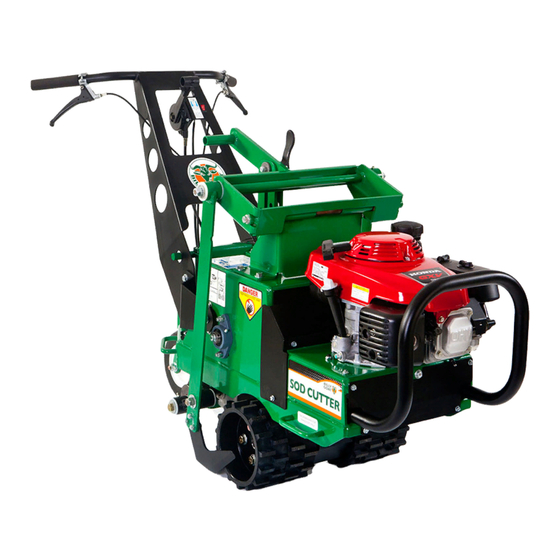
Billy Goat SC181H Operator's Manual
Hide thumbs
Also See for SC181H:
- Owner's manual (37 pages) ,
- Owner's manual (37 pages) ,
- Operator's manual (11 pages)
Table of Contents
Advertisement
Quick Links
Advertisement
Table of Contents

Related Manuals for Billy Goat SC181H


Summary of Contents for Billy Goat SC181H
-
Page 2: Table Of Contents
Table of Contents: Intended Use................. 3 Specifications................ 3 California Proposition 65............. 3 Initial Setup................3 Uncrating The Unit............3 Setup Checklist..............3 Features and Controls............3 Instructional Decals............3 Drive Controls..............5 Blade Engage Lever............5 Engine Stop Switch............5 Blade Height Adjuster............6 Free Wheel Lever.............6 Choke-Throttle Combination Lever........ -
Page 3: Intended Use
Maximum Operating Slope 20° The instructional decals shown below were installed on your ENGINE new Billy Goat 18" Sod Cutter. If any decals are damaged Type: Honda or missing, replace them before operation. Use the images and corresponding part numbers when ordering replacement... - Page 4 373500 - Decal, Console 373501 - Decal, Blade Arm 373503 - Decal, Height Adjuster 373504 - Decal, Drive Enable A. 373500 - Decal, Console B. 373501 - Decal, Blade Arm C. 373503 - Decal, Height Adjuster D. 373504 - Decal, Drive Enable E.
-
Page 5: Drive Controls
373505 - Decal, Service Instructions 371504 - Decal, Caster Right Drive Controls The drive controls are located on each side of the operator 400424 - Decal, Warning Sharp console. Engage the right lever to move forward (A, Figure 2). Engage the left lever to move in reverse (B). To increase speed, depress the lever gradually. -
Page 6: Blade Height Adjuster
Blade Height Adjuster The blade height adjuster is located in the center of the unit (A, Figure 3). To select cutting depth, lower the cam lever to unlock the blade height adjuster. Insert the depth control pin into the position corresponding to desired cutting depth. Use the chart provided on the instruction label 373503 to determine pin position. -
Page 7: Operation
Operation ground conditions allow, increase or decrease the ground speed of the unit. To gradually increase speed, gradually depress the lever. The unit operates at maximum speed Before Operation with the lever fully depressed. The unit operates at minimum speed with the lever minimally depressed. As with all mechanical tools, use reasonable care during operation. -
Page 8: Belt Maintenance
6. Slip the damaged or worn drive belt from around the Maintenance Each Use transmission pulley (D). From a position at the front of the Operation unit, gently pull the belt, navigating it around the idler arm Replace engine (B). air filter. -
Page 9: Blade Maintenance
1. Park the unit on a flat, level surface. Turn off the engine Note: The blade wears faster when operating in dry and/or and disconnect the spark plug wire. sandy conditions. Under these conditions, it will need to be 2. To adjust cable tension, adjust the barrel length (A, replaced more frequently. - Page 10 Problem Possible Cause Solution Engine is locked and Oil is present in the Remove sparkplug and will not pull over. engine cylinder. turn engine over to clear oil out. Refer to the engine manufacturer Engine is damaged. owner's manual. Refer to engine manufacturer owner's manual or contact your Authorized Service...
- Page 11 Gearbox Assembly Gearbox Assembly...
- Page 12 371203-S 371203-S SHCS, 5/16-18 X 1.25 BLK OX W/RED PATCH SHCS, 5/16-18 X 1.25 BLK OX W/RED PATCH 362289 362289 ROD, CONNECTING ASSY SC181H ROD, CONNECTING ASSY SC181H 373016 373016 GEARBOX, SPIRAL BEVEL 2:1 CURTIS GEARBOX, SPIRAL BEVEL 2:1 CURTIS...
- Page 13 Wheel Drive Assembly Wheel Drive Assembly...
- Page 14 SPROCKET, #40 X 25 TEETH, THREE HOLE MOU 373227 373227 373227 373227 WHEEL, DRIVE SOD CUTTER WHEEL, DRIVE SOD CUTTER 373228 373228 WHEEL, DRIVE SC181H GOLF WHEEL, DRIVE SC181H GOLF 373321 373321 SPROCKET, 40B42, 1.00” BORE SPROCKET, 40B42, 1.00” BORE 373317 373317 373317...
- Page 15 Handle Bar Assembly Handle Bar Assembly...
- Page 16 373310 SPACER, ROUND 5/8 OD X .252 ID X 1/2 LNG SPACER, ROUND 5/8 OD X .252 ID X 1/2 LNG 373309 373309 CLEVIS, CLUTCH CONTROL SC181H CLEVIS, CLUTCH CONTROL SC181H 373290 373290 PIN CLEVIS 1/4” X 1 11/16” ZP PIN CLEVIS 1/4”...
- Page 17 Height Adjust Assembly (Part 1) Height Adjust Assembly (Part 1)
- Page 18 Height Adjust Assembly (Part 1) Height Adjust Assembly (Part 1) SC181H SC181H SC181HG SC181HG Item No. Item No. Description Description Part No. Part No. INSERT GLIDE 1 INCH 10-14 GA INSERT GLIDE 1 INCH 10-14 GA 890132 890132 BRACKET, DEPTH CONTROL LH...
- Page 19 Height Adjust Assembly (Part 2) Height Adjust Assembly (Part 2)
- Page 20 LOWER HEIGHT ADJUST BRACKET WA LOWER HEIGHT ADJUST BRACKET WA 373110 373110 371259 371259 SHAFT PIVOT BEARING SHAFT PIVOT BEARING ARM, BLADE SC181H WA ARM, BLADE SC181H WA 373014 373014 NUT LOCK 5/16-18 HEX GR8 NUT LOCK 5/16-18 HEX GR8 371286 371286...
- Page 21 Back Wheel Assembly Back Wheel Assembly...
- Page 22 NUT-HEX-NYLK, FLG .375”-16 ZP NUT-HEX-NYLK, FLG .375”-16 ZP 8165003 8165003 BLT-RDHDSSQNK, .375”-16 X 1.000 G5 ZP BLT-RDHDSSQNK, .375”-16 X 1.000 G5 ZP 8024058 8024058 REAR CASTER ASSY SC181H REAR CASTER ASSY SC181H 373018 373018 WA, CASTER WHEEL WA, CASTER WHEEL 382125 382125 WHEEL, 8”...
- Page 23 Transmission Assembly Transmission Assembly...
- Page 24 WASHER 5/16 FLAT ZP WASHER 5/16 FLAT ZP 8171003 8171003 NUT 5/16-24 FIN HEX ZP NUT 5/16-24 FIN HEX ZP 8149002 8149002 KIT, SC181H TRANSMISSION PULLEY KIT, SC181H TRANSMISSION PULLEY 373603 373603 SERVICE SERVICE BALL JOINT, ESL312 BALL JOINT, ESL312...
- Page 25 Frame and Blade Drive Assembly Frame and Blade Drive Assembly...
- Page 26 WSHR-STL, BLV, .323 X .717 X .055 CN MZ WSHR-STL, BLV, .323 X .717 X .055 CN MZ 8181010 8181010 SHAFT, BELLCRANK SHAFT, BELLCRANK 373239 373239 BELLCRANK, BLADE DRIVE SC181H BELLCRANK, BLADE DRIVE SC181H 373222 373222 PULLEY IDLER INSIDE 4” PULLEY IDLER INSIDE 4” 520061 520061 PULLEY IDLER 4.00”...
- Page 27 Engine Assembly Engine Assembly...
- Page 28 WSHR-STL, BLV, .402 X .877 X .063 CN MZ 8181011 8181011 SCREWCAP 3/8”-16 X 1 1/2” HCS ZP SCREWCAP 3/8”-16 X 1 1/2” HCS ZP 8041052 8041052 IDLER, TRANS. BELT SC181H WA IDLER, TRANS. BELT SC181H WA 373116 373116 WASHER 5/16 SAE Z/P WASHER 5/16 SAE Z/P 8172008 8172008 ENGINE 6.5 HP HONDA GSV190 N1L...
- Page 29 Speed Control Assembly Speed Control Assembly...
- Page 30 Speed Control Assembly Speed Control Assembly SC181H SC181H SC181HG SC181HG Item No. Item No. Description Description Part No. Part No. NUT-HEX-NYLK, FLG .375”-16 ZP NUT-HEX-NYLK, FLG .375”-16 ZP 8165003 8165003 CAM, SPEED CONTROL WA CAM, SPEED CONTROL WA 373112 373112...
- Page 31 Service Kit No. 373600 Service Kit No. 373600...
Need help?
Do you have a question about the SC181H and is the answer not in the manual?
Questions and answers