
Related Manuals for SST Automation GT200-EI-CA


Summary of Contents for SST Automation GT200-EI-CA
- Page 1 EtherNet/IP / CAN Gateway GT200-EI-CA User Manual V1.2 SST Automation Email: support@sstautomation.com www.SSTAutomation.com...
- Page 2 Important Information Warning The data and examples in this manual cannot be copied without authorization. SST Automation reserves the right to upgrade the product without notifying users. The product has many applications. The users must make sure that all operations and results are in accordance with the safety of relevant fields, and the safety includes laws, rules, codes and standards.
-
Page 3: Table Of Contents
Catalog 1 Product Overview ..............................1 1.1 Product Function ............................1 1.2 Product Feature ...............................1 1.3 Technical Specifications ..........................1 1.4 Revision History .............................2 2 Hardware Descriptions .............................. 3 2.1 Product Appearance ............................3 2.2 Indicators ................................ 4 2.3 DIP Switch ..............................4 2.4 Interface ................................4 2.4.1 Power and CAN Interface ........................ -
Page 4: Product Overview
1 Product Overview 1.1 Product Function GT200-EI-CA is a gateway that can realize mutual conversion between CAN protocol and EtherNet/IP protocol, and supports CAN2.0A/CAN2.0B devices to connect to EtherNet/IP Scanner for data communication. 1.2 Product Feature Supports one CAN interface. -
Page 5: Revision History
1.4 Revision History Revision Date Chapter Description V1.2 1/9/2023 New release www.SSTAutomation.com... -
Page 6: Hardware Descriptions
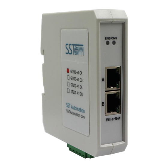
2 Hardware Descriptions 2.1 Product Appearance DIP switch Ethernet Status Indicator CAN Status Indicator Ethernet Interface Power and CAN Interface Notes: This picture is for reference only. The product appearance is subject to the actual product. www.SSTAutomation.com... -
Page 7: Indicators
BootLoader mode, with fixed IP address 192.168.0.10 Notes: After re-configuring DIP switch, you must restart the gateway GT200-EI-CA (power off and power on) to let the configuration take effect! After configuration is done, it is suggested to set the DIP switch to "2(OFF)1(ON)"(Run mode: only perform data exchange, but cannot be configured). -
Page 8: Ethernet Interface
CAN-L CAN-H Shield Wiring Pin 1 V+(optional) Pin 2 CAN-H Pin 3 Shield (optional) Pin 4 CAN-L Pin 5 GND, GND of 24V (optional) Notes: Here, shield port is optional. The CAN-L and CAN-H must be connected. Here pin 1 and 5 are connected to the pin 3 and pin 1 of power port internally. -
Page 9: Hardware Installation
3 Hardware Installation 3.1 Mechanical Dimension Size (width * height * depth): 1.0 in * 4.0 in * 3.6 in (25 mm * 100 mm * 90 mm) 3.2 Installation Method Using 1.4 in (35mm) DIN RAIL. www.SSTAutomation.com... -
Page 10: Quick Start Guide
4 Quick Start Guide 4.1 Gateway Configuration Use an Ethernet cable to connect the GT200-EI-CA to the PC. Set DIP Switch to "2(ON) , 1(OFF)". In configuration mode, use SST-EC-CFG configuration software to set parameters such as IP address and... -
Page 11: Software Instructions
5 Software Instructions 5.1 Precautions Please set the DIP Switch (2) to ON, (1) to OFF as the product is used for the first time, and configure the parameters in the static configuration. Noted the IP conflict will cause the start-up failure of the product. Users can upload/download configuration in the static configuration, the product cannot communicate with the devices in this process. -
Page 12: Search Device
5.2.2 Search Device Click "Search Device" you can search all devices on the network. 5.2.3 IP Search "IP Search" can search specified device by IP address, thereby configure this device. At this time, it only lists the device using the IP address. www.SSTAutomation.com... -
Page 13: Configuration
5.2.4 Configuration Select a device in the list, then the "Configure" and "Remote Reset" become available, "Locate" reserved. www.SSTAutomation.com... -
Page 14: Industrial Ethernet
Click the "Configure" button or double-click the selected device, a window will pop up as follows: 5.2.5 Industrial Ethernet Configure Ethernet parameters including "Select Protocol", "Assign IP Mode", "IP Address", "Subnet Mask", "Gateway Address", "DNS1", "DNS2", and "VendCode". www.SSTAutomation.com... - Page 15 The parameters that can be configured as follows: Assign IP Mode: Supports Manual Assign and DHCP. IP Address: Set the IP address of the device. Subnet Mask: Set the subnet mask of the device. Gateway Address: Set the gateway address of the device. DNS1: Primary Domain name server (may not be set in LAN ).
-
Page 16: Can
5.2.6 CAN CAN Protocol Type: Supports CAN 2.0A and CAN 2.0B. Baud Rate: 10K-1Mbps 5.2.7 Save/Open Configuration Load Config.file-Open and display the configuration data saved in the computer. www.SSTAutomation.com... - Page 17 Save Config. File to PC: Save the configuration parameters to the computer (.chg) for later viewing, pay attention to save this file. Export Excel to PC: Save configuration parameters to computer (xls). Select the device in the list, click the "Save Config. File to PC" or "Export Excel to PC" button, and select the path to complete the operation.
-
Page 18: New
5.2.8 New Click the "New" button.Open the configuration interface after the parameters was initialized: Note: The "New" function is mainly used for off-line configuration. Namely: Configuration interface can also be opened without device in initialization parameters. 5.2.9 Remote Reset Click the "Remote Reset" button, as shown in the pop-up interface as follows. www.SSTAutomation.com... - Page 19 Click on "OK", then execute remote reset operation, the gateway will restart (power off and power on). Click on "Cancel", and then cancel the reset operation. www.SSTAutomation.com...
-
Page 20: Working Principle
6 Working Principle 6.1 Data Exchange Mode The communication mode between CAN and EtherNet/IP is asynchronous, as shown in the figure below: "Data 1" shows the data transmission process from EtherNet/IP to CAN. "Data 2" shows the data transmission process from CAN to EtherNet/IP. An EtherNet/IP I/O output can carry 1 CAN frames. -
Page 21: Instance 101 Data Byte Definition
Note: For AB PLC, when RSLogix 5000 configures I/O, input is 4 bytes more than output, and input is 20 bytes. 6.3 Instance 101 Data Byte Definition Data direction: EtherNet/IP -> CAN The corresponding meaning of 16 bytes is as follows: 16 bytes can only contain one CAN frame. Byte 8-15 Single/... -
Page 22: Instance 102 Data Byte Definition
Number data control If GT200-EI-CA received CAN frame on CAN network, the sequence number of input frame will add 1. Users decide whether to use these CAN frame according to the needs. For example: Send a CAN frame, the sequence number is 10, the data frame in CAN2.0A working mode, ID=0x123, and the data is 01 02 03 04 05 06 07 08.
Need help?
Do you have a question about the GT200-EI-CA and is the answer not in the manual?
Questions and answers