
Subscribe to Our Youtube Channel
Related Manuals for Intellinet 561341


Summary of Contents for Intellinet 561341
- Page 1 16-PORT GIGABIT ETHERNET POE+ WEB- MANAGED SWITCH WITH 2 SFP PORTS User Manual Model 561341 INT‐561341‐UM‐0421‐3...
-
Page 2: Table Of Contents
16-Port Gigabit Ethernet PoE+ Web-Managed Switch with 2 SFP Ports ABLE OF ONTENTS Product Introduction ............................ 4 Product Overview ..............................4 Features ................................4 Specifications ............................... 5 External Component Description ........................6 2.4.1 Front Panel ..................................6 2.4.2 Rear Panel ..................................8 Package Contents .............................. - Page 3 16-Port Gigabit Ethernet PoE+ Web-Managed Switch with 2 SFP Ports 6.6.2 PoE Port Configuration ............................... 47 6.6.3 PoE Delay Config ................................. 49 Spanning Tree Protocol (STP) ........................... 50 6.7.1 MSTP Region ................................53 6.7.2 MSTP Bridge ................................54 DHCP Relay Agent.............................. 56 6.8.1 DHCP Relay ..................................
-
Page 4: Product Introduction
16-Port Gigabit Ethernet PoE+ Web-Managed Switch with 2 SFP Ports RODUCT NTRODUCTION Congratulations on your purchase of the 16-Port PoE+ Web-Managed PoE+ Gigabit Ethernet Switch. Before you install and use this product, read this manual carefully for a full understanding of its functions. 2.1 P RODUCT VERVIEW... -
Page 5: Specifications
16-Port Gigabit Ethernet PoE+ Web-Managed Switch with 2 SFP Ports 2.3 S PECIFICATIONS Standards • IEEE 802.1d (Spanning Tree Protocol) • IEEE 802.1p (Traffic Prioritization) • IEEE 802.1q (VLAN Tagging) • IEEE 802.1w (Rapid Spanning Tree Protocol) • IEEE 802.3ad (Link Aggregation) •... -
Page 6: External Component Description
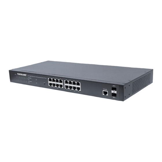
16-Port Gigabit Ethernet PoE+ Web-Managed Switch with 2 SFP Ports 2.4 E XTERNAL OMPONENT ESCRIPTION 2.4.1 Front Panel The front panel of the switch consists of 16 10/100/1000 Mbps RJ-45 ports, two SFP ports, one Console port, one Reset button and a series of LED indicators as shown below. 10/100/1000 Mbps RJ-45 ports (1~16): Designed to connect to the device with a bandwidth of 10Mbps, 100Mbps or 1000 Mbps. - Page 7 16-Port Gigabit Ethernet PoE+ Web-Managed Switch with 2 SFP Ports LED indicators: The LED indicators will allow you to monitor, diagnose and troubleshoot any potential problem with the switch, its connection or attached devices. The following chart shows the LED indicators of the switch along with explanation of each indicator. COLOR STATUS STATUS DESCRIPTION...
-
Page 8: Rear Panel
2.5 P ACKAGE ONTENTS Before installing the switch, make sure that the following items are enclosed. If any part is missing or damaged, contact your Intellinet agent immediately. • 16-Port Gigabit Ethernet PoE+ Web-Managed Switch with 2 SFP Ports •... -
Page 9: Installing And Connecting The Switch
16-Port Gigabit Ethernet PoE+ Web-Managed Switch with 2 SFP Ports NSTALLING AND ONNECTING THE WITCH This chapter describes how to install your Web-Managed Gigabit Ethernet PoE+ Switch and make connections to it. The following steps will help prevent damage to the device and maintain proper security: •... -
Page 10: Power On The Switch
16-Port Gigabit Ethernet PoE+ Web-Managed Switch with 2 SFP Ports Figure 5 - Bracket Installation Use the screws provided with the equipment rack to mount the switch on the rack and tighten it. Figure 6 - Rack Installation 3.3 P OWER ON THE WITCH The switch is powered on by connecting it to an outlet using the AC 100-240V 50/60Hz internal high-performance power... -
Page 11: Connection To The Switch
16-Port Gigabit Ethernet PoE+ Web-Managed Switch with 2 SFP Ports ONNECTION TO THE WITCH 4.1 C ONNECTING OMPUTER Use standard Cat5/5e Ethernet cables (UTP/STP) to connect the switch to end nodes as described below. Switch ports will automatically adjust to the characteristics (MDI/MDI-X, speed, duplex) of the device to which they are connected. Figure 7 - PC Connect The LNK/ACT/Speed LEDs for each port are illuminated when the link is available. - Page 12 16-Port Gigabit Ethernet PoE+ Web-Managed Switch with 2 SFP Ports Open the browser, and go to the URL http://192.168.2.1. The switch login window appears, as shown below. Enter the Username and Password (the factory default Username is admin and the Password is 1234 or the device serial number), and then click “LOGIN”...
-
Page 13: Saving The Configuration
AVING THE ONFIGURATION The Intellinet 16-Port Gigabit Ethernet PoE+ Web-Managed Switch provides a myriad of configuration options, many of which are designed for experienced network administrators and aren’t easy to configure. It would be a real shame if all the configuration data was lost after a power failure or after the switch was restarted. In order to make the configuration permanent, it needs to be saved. -
Page 14: Switch Configuration
If the CPU load is unusually high, or if the available memory or Flash memory is getting low, you may need to restart the Intellinet switch to free up system resources. Initiate the reboot via the SYSTEM -> SYSTEM CONFIG -> SYSTEM RESTART menu. - Page 15 16-Port Gigabit Ethernet PoE+ Web-Managed Switch with 2 SFP Ports 6.1.2.1 Port Information, Equipment Configuration and Port Statistics This section provides real-time information about the ports, basic settings and traffic statistics. Item Description Port Information Displays the port number. The nomenclature is as follows: Gi = Gigabit Ethernet 0/ = Switch 0 (which means this device) 1-18 = Port number.
-
Page 16: Quick Setup
UICK ETUP The Intellinet 16-Port Gigabit Ethernet PoE+ Web-Managed Switch provides a setting that offers direct access to some of the core functions of the device, namely VLAN, trunking, device IP address and admin password. Even though the function is called “Quickly Set,” there is no need to rush. Take as much time as you like with the configuration. -
Page 17: Port Settings
Access the parameters related to each of the 18 ports. The screen is divided into two sections. The upper section displays an image of the 18 ports of the Intellinet switch. In order to make changes to a port, simply click to select it. - Page 18 16-Port Gigabit Ethernet PoE+ Web-Managed Switch with 2 SFP Ports Item Description Working mode This parameter controls the duplex mode. In a full-duplex system, both parties can communicate to the other simultaneously. An example of a full-duplex device is a telephone;...
-
Page 19: Port Aggregation
16-Port Gigabit Ethernet PoE+ Web-Managed Switch with 2 SFP Ports 6.3.2 Port Aggregation Port aggregation is a method of using multiple Ethernet ports in parallel to increase throughput beyond what a single connection could sustain and to provide redundancy in case one of the links should fail. As this is essentially a grouping of ports into one logical unit, we call them Link Aggregation Groups, or “LAG”... -
Page 20: Port Mirroring
(i.e., a computer equipped with a packet sniffer utility). The Intellinet 16-Port Gigabit Ethernet PoE+ Web- Managed Switch provides up to four groups for port-mirroring settings. The example below shows setting up one mirror group where all traffic occurring on port 1 is being mirrored to port 16. -
Page 21: Port Speed Limit
6.3.4 Port speed limit This feature allows you to limit the data rates for a particular port on the Intellinet 16-Port Gigabit Ethernet PoE+ Web- Managed Switch. When the data rate exceeds user-configured values, the Intellinet switch drops packets immediately. -
Page 22: Broadcast Storm
Errors in the protocol-stack implementation or in the network configuration can cause a broadcast storm. The Intellinet switch allows configuring maximum allowed pps rates for three different types of packets. It's possible to set all 18 ports to the same value or provide individual values. -
Page 23: Port Isolation
16-Port Gigabit Ethernet PoE+ Web-Managed Switch with 2 SFP Ports 6.3.6 Port isolation The port isolation function allows you to configure the Intellinet switch in a way, that prevents PCs on different ports from communicating with each other, and all that without configuring a VLAN. - Page 24 16-Port Gigabit Ethernet PoE+ Web-Managed Switch with 2 SFP Ports 6.3.6.1 Configuration Example: Three PCs, one NAS, and one router are connected to the Intellinet switch PC1 is connected to Port 1 PC2 is connected to Port 2 PC3 is connected to Port 3...
- Page 25 16-Port Gigabit Ethernet PoE+ Web-Managed Switch with 2 SFP Ports NAS on Port 4: Router on Port 5: When completed, the configuration will look like this. To better understand what is happening, it helps to consider the isolated ports as the ports with which the source ports can communicate.
-
Page 26: Vlan
Access ports are designed to tag any incoming packet with the VLAN ID the port has been assigned to. b. Tagged VLAN packets arriving at the access port are dropped by the switch. As far as the Intellinet switch is concerned, any port that isn’t defined as a trunk or hybrid port is considered an access port. - Page 27 16-Port Gigabit Ethernet PoE+ Web-Managed Switch with 2 SFP Ports New VLAN: Item Description VLAN ID Type in the ID for the new VLAN. This value cannot be “1” nor any ID already setup on the switch. VLAN Name Provide a descriptive name for the VLAN (e.g., “VOICE”). Choose to join the VLAN port Select all the ports you wish to be a part of this VLAN.
-
Page 28: Trunk Port Settings
16-Port Gigabit Ethernet PoE+ Web-Managed Switch with 2 SFP Ports 6.4.1 Trunk Port Settings A trunk port transmits tagged packets and is used to connect different switches with one another. New Trunk-Port: Item Description Native VLAN ID The native VLAN ID is the untagged VLAN on an IEEE 802.1q trunked port. The native VLAN and management VLAN (see SYSTEM->SYSTEM CONFIG) can be the same, but in terms of security, it is better that they aren't. -
Page 29: Hybrid Port Settings
16-Port Gigabit Ethernet PoE+ Web-Managed Switch with 2 SFP Ports 6.4.2 Hybrid Port Settings A Hybrid port is a combination of a trunk and an access port. Item Description Native VLAN ID See previous trunk port section. VLAN TAG VLAN ID that is added to any untagged packet arriving at the port. Note: You cannot enter multiple IDs or ranges of IDs. -
Page 30: Setup Example
16-Port Gigabit Ethernet PoE+ Web-Managed Switch with 2 SFP Ports 6.4.3 Setup Example This section provides a real-life example and the corresponding setup of the Intellinet switch, or in this case, switches. • There are three VLANs in the network VLAN ID 100 –... - Page 31 Intellinet switch to do so. The Intellinet switch adds the VLAN ID 100 to all packets that are not tagged as VLAN ID 200. Port number two acts as an untagged port (VLAN ID 100) and tagged port (VLAN ID 200) at the same time, hence the name hybrid.
- Page 32 16-Port Gigabit Ethernet PoE+ Web-Managed Switch with 2 SFP Ports 6.4.3.2 Set up LAN Switch #2: VLAN ID 1 (default VLAN) only contains ports that are not otherwise assigned.
-
Page 33: Fault/Safety
16-Port Gigabit Ethernet PoE+ Web-Managed Switch with 2 SFP Ports 6.5 F AULT AFETY 6.5.1 Anti Attack 6.5.1.1 DHCP Snooping DHCP snooping is a security technology built into the operating system of a capable network switch that drops DHCP traffic determined to be unacceptable. The fundamental use for DHCP snooping is to prevent unauthorized (rogue) DHCP servers offering IP addresses to DHCP clients. - Page 34 When DHCP snooping is enabled, DHCP messages entering an untrusted interface are filtered based upon dynamic entries learned via DHCP snooping. Item Description Native Protection Status Closed: All DHCP related traffic will pass through the Intellinet switch without any interference. Open: Activates DHCP snooping. DHCP traffic is now subject to certain rules. DHCP Trusted Port These are trusted ports on your network, which are under your direct administrator control.
- Page 35 16-Port Gigabit Ethernet PoE+ Web-Managed Switch with 2 SFP Ports Source MAC Verify Enable Check to activate MAC address verification. MAC Address Type in the MAC address (format xx:xx:xx:xx:xx:xx). Verify / No Verify Verify: Adds MAC address to the configuration. No Verify: Removes previously entered MAC address from configuration.
- Page 36 16-Port Gigabit Ethernet PoE+ Web-Managed Switch with 2 SFP Ports When DHCP snooping is enabled, the lease information from the switching device is used to create the DHCP snooping database, also known as the DHCP snooping binding table. The table shows the IP-MAC binding, as well as the lease time for the IP address, type of binding, VLAN name and interface for each host.
- Page 37 DHCP snooping binding table (see section 6.5.1.1) or manually configured IP source bindings. Equipped with this feature, the Intellinet switch helps prevent IP spoofing attacks. An IP spoofing attack is when a host tries to spoof (fake) and use the IP address of another host in order to intercept traffic bound for that host.
- Page 38 16-Port Gigabit Ethernet PoE+ Web-Managed Switch with 2 SFP Ports Item Description VLAN ID Specify the VLAN ID for the static entry. Leave 1 for the default VLAN. Source IP Address Specify the IP address of the client for the static entry. Source MAC Address Specify the MAC address of the client for the static entry.
- Page 39 6.5.1.4 IP MAC Port Binding The Intellinet 16-Port Gigabit Ethernet PoE+ Web-Managed Switch features IP-MAC-Port Binding. This is a powerful authentication function that ensures the correctness of hardware (MAC address), software/user (IP address), and location (Connected port) for devices connected to the network. This feature ensures they are all from legal sources to prevent the data leakage from hackers faking the legal network devices.
-
Page 40: Channel Detection
16-Port Gigabit Ethernet PoE+ Web-Managed Switch with 2 SFP Ports 6.5.2 Channel Detection The Intellinet switch is equipped with a set of network tools that can aid the network administrator in troubleshooting problems. 6.5.2.1 Ping Item Description Destination IP address IP address you wish to ping. - Page 41 16-Port Gigabit Ethernet PoE+ Web-Managed Switch with 2 SFP Ports 6.5.2.3 Cable Test The cable test utility allows a quick check of the connected cables. Item Description Select Port Select one of the 18 ports, then click on “Start test.” Test Results Displays the results of the cable test.
-
Page 42: Acl Access Control List
ACL rules. The example below shows the setup of a timetable called “WorkingHours.” Note that the Intellinet switch must be set up with a proper system time (see section System Config). - Page 43 16-Port Gigabit Ethernet PoE+ Web-Managed Switch with 2 SFP Ports 6.5.3.2 In this section, set up the actual access control list (ACL). The ACL connects IP address and port information with a timetable (see section 6.5.3.1) and an action to either allow or deny access to the network through the switch. The example below creates an ACL, which allows access to the network for any computer Item Description...
- Page 44 16-Port Gigabit Ethernet PoE+ Web-Managed Switch with 2 SFP Ports Example 2 – Disallow access to the network for an individual IP address during the working hours. 6.5.3.3 Application ACL With this function you can link an ACL to one or more of the 18 available switch ports. Select the ports and ACL list, and click “Save”...
-
Page 45: Power Over Ethernet (Poe)
16-Port Gigabit Ethernet PoE+ Web-Managed Switch with 2 SFP Ports 6.6 P OWER OVER THERNET The Intellinet 16-Port Gigabit Ethernet PoE+ Web-Managed Switch is equipped with sophisticated PoE-monitoring and configuration options. 6.6.1 PoE Configuration 6.6.1.1 Management Item Description Working status Displays the value “On-line,”... - Page 46 Click in order to edit the temperature threshold of the PoE chips. Note that in order for the Intellinet PoE switch to send our SNMP traps, SNMP must be activated and configured.
-
Page 47: Poe Port Configuration
16-Port Gigabit Ethernet PoE+ Web-Managed Switch with 2 SFP Ports 6.6.2 PoE Port Configuration This section describes how to edit the parameters of individual PoE ports. Upon opening the configuration screen, an overview of the PoE ports and their current statuses appears. Click on order to modify individual ports. - Page 48 This ensures that these cameras will always be supplied with power, even if the total power draw on the Intellinet switch exceeds the maximum available PoE power. Ports that are set to low or mid will be disconnected first –...
-
Page 49: Poe Delay Config
(i.e., your PoE-enabled network cameras). The restart time allows to cut power to the PSE ports of the Intellinet switch in order to restart a connected powered device. This can be used in order to preventively reboot powered devices to keep them from failing. -
Page 50: Spanning Tree Protocol (Stp)
16-Port Gigabit Ethernet PoE+ Web-Managed Switch with 2 SFP Ports 6.7 S (STP) PANNING ROTOCOL The Spanning Tree Protocol can be used to detect and disable network loops and to provide backup links between switches, bridges or routers. This allows the switch to interact with other bridging devices in your network to ensure that only one route exists between any two stations on the network. - Page 51 16-Port Gigabit Ethernet PoE+ Web-Managed Switch with 2 SFP Ports STP communicates between switches on the network using Bridge Protocol Data Units (BPDUs). Each BPDU contains the following information: • The unique identifier of the switch that the transmitting switch currently believes is the root switch •...
- Page 52 16-Port Gigabit Ethernet PoE+ Web-Managed Switch with 2 SFP Ports Each port on a switch using STP exists is in one of the following five states: • Blocking – the port is blocked from forwarding or receiving packets • Listening – the port is waiting to receive BPDU packets that may tell the port to go back to the blocking state •...
-
Page 53: Mstp Region
16-Port Gigabit Ethernet PoE+ Web-Managed Switch with 2 SFP Ports 6.7.1 MSTP Region Item Description MSTP Region Configuration Each switch running MST in the network has a single MST configuration that consists of these two attributes: Region name An alphanumeric configuration name Revision Level Instance Mapping A table that associates each of the potential 4096 VLAN IDs to a given... -
Page 54: Mstp Bridge
16-Port Gigabit Ethernet PoE+ Web-Managed Switch with 2 SFP Ports 6.7.2 MSTP Bridge Item Description inst-priority Priority can be configured for a specified instance. inst-id Select the instance ID for which you want to define a priority. Priority Select the priority level for the instance ID. Enable Enable / disable STP. - Page 55 16-Port Gigabit Ethernet PoE+ Web-Managed Switch with 2 SFP Ports Item Description inst Select the instance ID. port-fast The time Spanning Tree Protocol (STP) takes to transition ports over to the forwarding state can cause problems. Port-fast is a function to resolve this problem. Port-fast solves the problem of delays when client computers are connecting to switches.
-
Page 56: Dhcp Relay Agent
DHCP packets between clients and servers. Relay agents are used to forward requests and replies between clients and servers when they are not on the same physical subnet. The Intellinet switch can fulfill the role of such a relay agent. - Page 57 16-Port Gigabit Ethernet PoE+ Web-Managed Switch with 2 SFP Ports 6.8.2.2 Proxy Remote Item Description Proxy Remote ASCII Remote ID string, up to 63 characters. VLAN ID Type in the VLAN ID. Use value 1 for the default VLAN. 6.8.2.3 IP Address Item Description...
-
Page 58: Dhcp Server
Defines how long the client is allowed to keep the IP address. When the time has elapsed, the switch will issue a new IP address to the client. Note: The DHCP IP address range must be in the same range as the Intellinet switch's LAN IP range (e.g., 192.168.2.xxx). - Page 59 Provide the value fort the tag (code) you selected. 6.9.1.4 Bind Config This page displays all clients that have obtained an IP address from the Intellinet switch. Click on to set the lease time to expired, forcing the connect client to obtain a new IP address instantly.
- Page 60 16-Port Gigabit Ethernet PoE+ Web-Managed Switch with 2 SFP Ports 6.9.1.6 DNS Config On this page, provide the DNS IP address(es) that you wish to provide to the DHCP clients.
-
Page 61: Terminal Access Controller Access-Control System (Tacacs+)
Global Config Global parameters that can be overwritten by port-specific configuration. Server timeout The global timeout interval determines how long the Intellinet switch waits for responses from TACACS+ servers before declaring a timeout failure. Server retry Specifies the number of retry attempts that will be made to establish a Transmission count Control Protocol (TCP) connection between a TACACS+ client and the TACACS+ server. - Page 62 Define the TCP port number of the TACSACS+ server connection. Server timeout The timeout interval determines how long the Intellinet switch waits for responses from a specific TACACS+ server before declaring a timeout failure. If left empty, the global server timeout value will be used; otherwise, the server timeout takes precedence.
-
Page 63: Radius
RADIUS server before the server is considered unavailable. Dead-criteria timeout Set the time in seconds during which the Intellinet switch does not need to get a valid response from the RADIUS server. The range is from 1 to 120 seconds. -
Page 64: Radius Server Config
The key parameter in the radius-server command is used to encrypt RADIUS packets before they are sent over the network. The value for the key parameter on the Intellinet switch device should match the one configured on the RADIUS server. The default value is “radius”. -
Page 65: Aaa
16-Port Gigabit Ethernet PoE+ Web-Managed Switch with 2 SFP Ports 6.12 AAA Authentication, authorization and accounting (AAA) is a system for tracking user activities on an IP-based network and controlling their access to network resources. AAA is often is implemented as a dedicated server. 6.12.1 Enable Config Enable or disable AAA. -
Page 66: Server Config
16-Port Gigabit Ethernet PoE+ Web-Managed Switch with 2 SFP Ports 6.12.3 Server Config Item Description Server name Type in the name for the server. This can be a descriptive name for easier identification. Server IP addr Provide the IP address of the RADIUS or TACACS+ server. Select server Set to either RADIUS or TACACS+. -
Page 67: Aaa Authentication
16-Port Gigabit Ethernet PoE+ Web-Managed Switch with 2 SFP Ports 6.12.4 AAA Authentication 6.12.4.1 Login Authentication Item Description Choose a domain Select the ISP domain. Login Authentication Check to activate it. First – Fourth Method None: Eliminates the requirement for any authentication method. Local: Uses the local password configured on the device to grant access. - Page 68 Note: If you activate this but have not configured any of the authentication methods (i.e., RADIUS) correctly, you will lose access to the Intellinet switch, and you may need to perform a hardware reset in order to re-gain access to the web...
-
Page 69: Qos - Quality Of Service
16-Port Gigabit Ethernet PoE+ Web-Managed Switch with 2 SFP Ports 6.13 Q S – Q UALITY OF ERVICE Quality of Service (QoS) is an advanced traffic prioritization feature that allows you to establish control over network traffic. QoS enables the assigning of various grades of network service to different types of traffic such as multi-media, video, protocol-specific, time critical and file-backup traffic. -
Page 70: Queue Config
Select the port or ports for the QoS rule. Select all ports if you want the rule to apply to whichever port the devices are connected to. 6.13.2 Queue Config In this section, define which priority algorithm you wish the Intellinet switch to utilize. Item Description... -
Page 71: Queue Mapping
ID, and the QUEUE ID is listed as the server list on the screen. 6.13.3.3 Port-CoS-Map This page allows the network administrator to classify CoS settings to the 18 physical ports on the Intellinet switch. The server ID represents the CoS ID. -
Page 72: Address Table
DDRESS ABLE To switch data packets between LAN ports efficiently, the Intellinet switch maintains an address table. When the switch receives a frame, it associates the media access control (MAC) address of the sending network device with the LAN port on which it was received. - Page 73 The default aging time is 300 seconds. Setting the value to “0” disables the aging time mechanism, which means that the MAC address table will keep the learned address until the switch is reset. Since the Intellinet switch has only finite space to hold MAC addresses, it is recommended to keep the aging time at or around the default value.
-
Page 74: Snmp
16-Port Gigabit Ethernet PoE+ Web-Managed Switch with 2 SFP Ports 6.15 SNMP Simple Network Management Protocol (SNMP) is an OSI Layer 7 (Application Layer) designed specifically for managing and monitoring network devices. SNMP enables network management stations to read and modify the settings of gateways, routers, switches and other network devices. - Page 75 16-Port Gigabit Ethernet PoE+ Web-Managed Switch with 2 SFP Ports 6.15.1.2 Group Config The Intellinet switch uses a view-based access control model that allows the network administrator to configure the access privileges granted to a group. Item Description Group name Provide a group name.
- Page 76 16-Port Gigabit Ethernet PoE+ Web-Managed Switch with 2 SFP Ports 6.15.1.3 User Config This section allows setting up SNMP users and assigning them to an SNMP group. Item Description User name Provide a group name. Security level Select the desired security level. Group name Provide a group name.
- Page 77 16-Port Gigabit Ethernet PoE+ Web-Managed Switch with 2 SFP Ports 6.15.1.4 Trap Config SNMP traps are alerts generated by agents on a managed device. Item Description Destination IP Address The IP address of the SNMP manager (TRAP viewer). Address type IPv4 (and perhaps later IPv6 will be supported) Security name When using security mode v3, select a user from a drop down list.
- Page 78 16-Port Gigabit Ethernet PoE+ Web-Managed Switch with 2 SFP Ports 6.15.1.5 View Config SNMPv3 defines the concept of Management Information Base (MIB) views in RFC 3415, View-based Access Control Model (VACM) for SNMP. MIB views provide an agent better control over who can access specific branches and objects within its MIB tree.
-
Page 79: Rmon Config
SNMP management terminals and remote monitors. RMON provides a highly efficient method to monitor actions inside the subnets. MID of RMON consists of 10 groups. The Intellinet 16-Port Gigabit Ethernet PoE+ Web-Managed Switch supports the most frequently used groups 1, 2, 3 and 9: •... - Page 80 16-Port Gigabit Ethernet PoE+ Web-Managed Switch with 2 SFP Ports 6.15.2.1 Statistics Group Item Description Index Specify the history table index number. Select one of the eighteen Gigabit port from the drop-down list. Interface name Optional field that allows the network administrator to enter the name of the Owner owner of the Statistics RMON group.
- Page 81 16-Port Gigabit Ethernet PoE+ Web-Managed Switch with 2 SFP Ports This is the number of samples ("buckets") to keep before they are overwritten. Maximum number of samples Sample period The number of seconds in each polling cycle. 6.15.2.3 Alarm Group Item Description Index...
- Page 82 16-Port Gigabit Ethernet PoE+ Web-Managed Switch with 2 SFP Ports 6.15.2.4 Event Group Item Description Index Specify the event table index number. A descriptive name of the event. Description Optional field that allows the network administrator to enter the name of the Owner owner of the Event RMON group.
-
Page 83: System
Mask The optional default gateway only is needed when you require Internet access for Default Gateway the Intellinet switch, for example in order to obtain time information from an NTP server. Jumboframe Here you can specify the maximum frame size supported by the Intellinet switch. - Page 84 Click in order to set the time for the Intellinet switch manually. Set time [ ] NTP Server Activate this option for the Intellinet switch to obtain the system time from an NTP server. For that to work, be sure to provide a proper gateway and DNS server address.
- Page 85 Using this technique, more power can be saved if the traffic can be buffered up until a large burst of traffic can be transmitted. Keep in mind that buffering traffic will give some latency in the traffic. Should you encounter problems related to EEE (e.g., related to auto negotiation), disable EEE support and the Intellinet switch will no longer use it.
- Page 86 System Log The Intellinet PoE switch can create a history log of important events. These logs can be stored either in the switch's own memory or on a remote Syslog server. In order to utilize the logging service, you must first enable it.
-
Page 87: System Update
16-Port Gigabit Ethernet PoE+ Web-Managed Switch with 2 SFP Ports 6.16.2 System Update Intellinet may release a new firmware for this switch proving new functions and perhaps bug fixes. Install the new firmware on this screen. Should a new firmware be made available, it will be available at http://intellinet- network.com/search?q=561341. -
Page 88: Configuration Management
16-Port Gigabit Ethernet PoE+ Web-Managed Switch with 2 SFP Ports 6.16.3 Configuration Management 6.16.3.1 Config Export and Import This function allows for backing-up and restoring the configuration data of the Intellinet switch. Item Description Shows the current switch configuration in a pop-up window. -
Page 89: Config Save
6.16.5 User Accounts This page is designed to configure user accounts. A user account that does not have administrator rights can only monitor the main status information of the Intellinet switch, but cannot make any changes to the configuration. Item... -
Page 90: Information Collect
Click on the button create a file that contains the configuration data of the Intellinet switch. A few seconds later, you will be asked to open or save the file (or whatever web browser default action for unknown files is in place on your... -
Page 91: Warranty
Polski - Informacje dotyczące gwarancji znajdują się na stronie intellinetnetwork.com/warranty. México - Póliza de Garantía Intellinet — Datos del importador y responsable ante el consumidor IC Intracom México, S.A.P.I. de C.V. • Av. Interceptor Poniente # 73, Col. Parque Industrial La Joya, Cuautitlan Izcalli, Estado de México, C.P. -
Page 92: Copyright
16-Port Gigabit Ethernet PoE+ Web-Managed Switch with 2 SFP Ports OPYRIGHT Copyright ©2015 IC Intracom. All rights reserved. No part of this publication may be reproduced, transmitted, transcribed, stored in a retrieval system, or translated into any language or computer language, in any form or by any means, electronic, mechanical, magnetic, optical, chemical, manual or otherwise, without the prior written permission of this company This company makes no representations or warranties, either expressed or implied, with respect to the contents hereof... -
Page 93: Federal Communication Commission Interference Statement
16-Port Gigabit Ethernet PoE+ Web-Managed Switch with 2 SFP Ports EDERAL OMMUNICATION OMMISSION NTERFERENCE TATEMENT This equipment has been tested and found to comply with the limits for a Class B digital device, pursuant to Part 15 of FCC Rules. These limits are designed to provide reasonable protection against harmful interference in a residential installation. - Page 94 16-Port Gigabit Ethernet PoE+ Web-Managed Switch with 2 SFP Ports intellinetnetworkcom © IC Intracom. All rights reserved. Intellinet is a trademark of IC Intracom, registered in the U.S. and other countries.
Need help?
Do you have a question about the 561341 and is the answer not in the manual?
Questions and answers