HMS Anybus Serial Server User Manual
Hide thumbs
Also See for Anybus Serial Server:
- User manual (55 pages) ,
- Manual (20 pages) ,
- Installation manual (12 pages)
Table of Contents
Advertisement
Quick Links
Advertisement
Table of Contents

Related Manuals for HMS Anybus Serial Server


Summary of Contents for HMS Anybus Serial Server
- Page 1 User Manual Anybus Serial Server ® Rev. 1.40:1 HMS Industrial Networks AB Germany + 49 - 721 - 96472 - 0 ge-sales@hms-networks.com Japan + 81 - 45 - 478 -5340 jp-sales@hms-networks.com Sweden + 46 - 35 - 17 29 20 sales@hms-networks.com...
-
Page 3: Table Of Contents
Important User Information ......................P-1 Related Documents..........................P-2 Document History ..........................P-2 Conventions & Terminology......................P-3 Support ..............................P-3 Chapter 1 About the Anybus Serial Server General..............................1-1 Mounting ..............................1-2 Mac ID & Default IP Address ......................1-2 Connectors .............................1-3 Overview ............................1-3 I/O &... -
Page 4: Preface
Microsoft Windows operating system. Important User Information The data and illustrations found in this document are not binding. We, HMS Industrial Networks AB, reserve the right to modify our products in line with our policy of continuous product development. The information in this document is subject to change without notice and should not be considered as a com- mitment by HMS Industrial Networks AB. -
Page 5: Related Documents
About This Document P-2 Related Documents Document name Author Document History Summary of Recent Changes (v1.20:1... v1.40:1) Change Page(s) Updated figures etc. to reflect changes in product 1-3... 1-5 Added information about modem control lines Revision List Revision Date Author(s) Chapter(s) Description 1.00 03-03-02 JOAK... -
Page 6: Conventions & Terminology
Numbered lists provide sequential steps • Bulleted lists provide information, not procedural steps • The term ‘Serial Server’ is refers to the Anybus Serial Server • EIA-485 is also commonly referred to as RS-485 • EIA-232 is also commonly referred to as RS-232... -
Page 7: About The Anybus Serial Server
Ethernet (Anybus Serial Server) (Computer with Serial/IP software) (Serial Device) (Serial Device) The Anybus Serial Server connects serial devices to Ethernet networks using the IP protocol family. Some different types of serial devices supported are listed below: • Scanners •... -
Page 8: Mounting
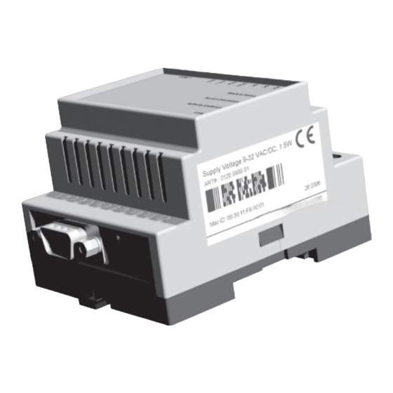
About the Anybus Serial Server 1-2 Mounting A: Snap On B: Snap Off Procedure 1. Snap the Serial Server on to the DIN-rail (as described on pictures above). 2. Connect the Ethernet cable to the RJ45 connector. 3. Connect the serial device to the 9-pole DSUB connector. -
Page 9: Connectors
About the Anybus Serial Server 1-3 Connectors Overview Description Comments I/O & Power Interface See 1-4 “I/O & Power Interface” EIA-232 Interface See 1-4 “EIA-232 Interface” Ethernet Interface See 1-4 “Ethernet Interface”... -
Page 10: I/O & Power Interface
About the Anybus Serial Server 1-4 I/O & Power Interface Signal Comments Vin+ Voltage Range: 9... 32VAC/DC Vin- (Ground connection) Digital in 1+ Digital in 2- Digital Input Common (not connected) EIA-232 Receive (Not used) EIA-232 Transmit EIA-485 Common This port can be used to connect to any equipment with an EIA-485 interface. -
Page 11: Indicators
About the Anybus Serial Server 1-5 Indicators RS-485 RS-232 Status Status Serial Link Serial Link Activity Activity S E R I A L S E R V E R Link Link RS-232 ETHERNET State Function Module Status No power Green... -
Page 12: Chapter 2 Configuration
• Installation Procedure There are two methods to install the Anybus IPconfig utility, either downloading it from the HMS website or use the installation CD ROM. - Using the CD ROM: Run “Setup-AnybusIPconfig.exe” and follow the on-screen instruc- tions. - From website: Download the self-extracting installation package “Setup-AnybusIPcon- fig.exe”... -
Page 13: Changing The Ip Settings
Configuration 2-2 Changing the IP Settings To change the IP settings on a detected device, double-click on the device you want to configure in the list of devices. This will open up a dialog where you can enter the desired IP configuration. Field Contents IP Address... -
Page 14: Installing The Windows Driver (Serial/Ip)
General Information To be able to use the Serial Server you need to install the Serial/IP driver on a PC. For installation in- structions, consult the “Serial/IP Quick Start” available at the HMS website (‘www.anybus.com’). Log In Open a web browser (e.g. Internet Explorer) and enter the IP address you have set on the Serial Server unit with the Anybus IPconfig utility. -
Page 15: Network Settings
Configuration 2-4 Network Settings If you press the Network link you will be presented with the following view. On this page you can view and change the TCP/IP network settings in the device. These settings are the same as the ones set by the Anybus IPconfig utility. To obtain the necessary information about IP ad- dress, Subnet mask etc. -
Page 16: Serial Port Settings (Configuration)
Configuration 2-5 Serial Port Settings (Configuration) If you press the Configuration link you will be presented with the following view. The page is divided in two sections, one for each serial port. All fields exist for both ports except that the EIA-485 port has no flow control selection. -
Page 17: Password Settings
Configuration 2-6 Field Description For the EIA-232 port you can select if you want flow control handled by the UART. If this is Flow Control selected then transmit is automatically stopped/continued when serial buffer is full/available. You can choose between NONE, CTS/RTS and XON/XOFF. NONE disables UART flow con- trol. -
Page 18: Appendix 3
Appendix 3 Technical Specification Ethernet Interface • 10Base-T or 100Base-TX (IEEE 802.3) • RJ45 Connector Serial Interface (EIA-232) • EIA-232 with full modem control (RTS,CTS,DCD,DTR,DSR,RI) • 300... 115.200bps operation • 9-pole DSUB connector Power Supply Requirements • 9... 32 VAC/DC •...
Need help?
Do you have a question about the Anybus Serial Server and is the answer not in the manual?
Questions and answers