
Related Manuals for HMS Intesis INMBSMIT050C000


Summary of Contents for HMS Intesis INMBSMIT050C000
- Page 1 Mitsubishi Electric Centralized Controller TCP/ IP XML Gateway for integration of Mitsubishi Elctric City Multi air conditioning system into Modbus (RTU and TCP) systems USER MANUAL Issue date: 05/2019 r1.1 ENGLISH...
- Page 2 HMS Industrial Networks reserves the right to modify its products in line with its policy of continuous product development. The information in this document shall therefore not be construed as a commitment on the part of HMS Industrial Networks and is subject to change without notice.
- Page 3 Gateway for integration of Mitsubishi Electric City Multi air conditioning systems into Modbus (RTU and TCP) systems. ORDER CODE LEGACY ORDER CODE INMBSMIT050C000 ME-AC-MBS-50 INMBSMIT100C000 ME-AC-MBS-100 © HMS Industrial Networks S.L.U - All rights reserved https://www.intesis.com This information is subject to change without notice 3 / 25...
-
Page 4: Table Of Contents
4.1.6 Diagnostic ............................21 Set-up procedure ..............................23 5 Electrical & Mechanical Features ........................24 6 Dimensions ................................. 25 © HMS Industrial Networks S.L.U - All rights reserved https://www.intesis.com This information is subject to change without notice 4 / 25... -
Page 5: Description
Modbus TCP configuration Modbus RTU Ethernet configuration Integration of Mitsubishi's Centralized Controller into Modbus TCP / Modbus RTU control systems © HMS Industrial Networks S.L.U - All rights reserved https://www.intesis.com This information is subject to change without notice 5 / 25... -
Page 6: Functionality
INMBSMIT050C000. Model supporting up to 50 City Multi groups. • INMBSMIT100C000. Model supporting up to 100 City Multi groups. © HMS Industrial Networks S.L.U - All rights reserved https://www.intesis.com This information is subject to change without notice 6 / 25... -
Page 7: Modbus Interface
(cc x 30) + 0 Centralized controller communication error 0-Ok, 1-Communication error cc stands for centralized controller number and is 0 or 1 © HMS Industrial Networks S.L.U - All rights reserved https://www.intesis.com This information is subject to change without notice 7 / 25... - Page 8 Vane position (all the IC groups) 1-Set Vanes Vertical (cc x 30) + 24 Vane position (all the IC groups) 1-Set Vanes Swing © HMS Industrial Networks S.L.U - All rights reserved https://www.intesis.com This information is subject to change without notice 8 / 25...
-
Page 9: City Multi Group Signals
Cool or dry:19..30 ºC; Heat or ((cc x 50) + g) x 100 + 4 Temperature Setpoint (ºC) Auto:17..28 ºC © HMS Industrial Networks S.L.U - All rights reserved https://www.intesis.com This information is subject to change without notice 9 / 25... - Page 10 Maximum heat setpoint restriction 4.5..35ºC ((cc x 50) + g) x 100 + 25 Minimum auto setpoint restriction 4.5..35ºC © HMS Industrial Networks S.L.U - All rights reserved https://www.intesis.com This information is subject to change without notice 10 / 25...
- Page 11 0-Ok, 1-Dirty ((cc x 50) + g) x 100 + 37 Dirty filter indication reset 1: Reset the filter © HMS Industrial Networks S.L.U - All rights reserved https://www.intesis.com This information is subject to change without notice 11 / 25...
-
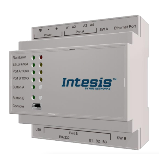
Page 12: Connections
Connect a USB storage device (not a HDD) if required. Check the user manual for more information. Ensure proper space for all connectors when mounted (see section 66). © HMS Industrial Networks S.L.U - All rights reserved https://www.intesis.com This information is subject to change without notice... -
Page 13: Power Device
• USB cable: To connect the device to the PC, the USB cable supplied should be plugged to the USB Console port. © HMS Industrial Networks S.L.U - All rights reserved https://www.intesis.com This information is subject to change without notice... -
Page 14: Set-Up Process And Troubleshooting
4.1.2 Connection To configure the Intesis connection parameters press on the Connection button in the menu bar. Figure 4.1 MAPS connection © HMS Industrial Networks S.L.U - All rights reserved https://www.intesis.com This information is subject to change without notice 14 / 25... -
Page 15: Configuration Tab
Up to two Centralized Controller’s can be configured (depending on the Intesis version). Each Centralized controller must be configured with the following parameters: © HMS Industrial Networks S.L.U - All rights reserved https://www.intesis.com This information is subject to change without notice... - Page 16 You can also scan for available groups under the IP of the Centralized Controller: Figure 4.4 Selection of active groups in Centralized Controller By pressing the ‘Scan’ button, ‘Discover Controller Groups’ window will appear: © HMS Industrial Networks S.L.U - All rights reserved https://www.intesis.com This information is subject to change without notice...
- Page 17 ‘Discover Control Groups’ also allows to Export Controller Configuration (see corresponding button in Figure 4.6), which will generate a text file with the active groups in the controller, for documentation and support purposes. © HMS Industrial Networks S.L.U - All rights reserved https://www.intesis.com...
- Page 18 3. Setpoint type: Select if unit supports different setpoints according to operation mode, or it supports single setpoint. 4. URC Controller: Select if unit has URC controller © HMS Industrial Networks S.L.U - All rights reserved https://www.intesis.com This information is subject to change without notice...
- Page 19 3. Controller Connection Timeout: After Intesis starts TCP/IP socket connection, time that the Intesis will wait for the Centralized Controller to accept the socket request. For each individual request, Intesis starts a new socket connection. © HMS Industrial Networks S.L.U - All rights reserved https://www.intesis.com This information is subject to change without notice...
-
Page 20: Signals
3.- Press the Send File button to send the binary file to the Intesis device. The process of file transmission can be monitored in the Intesis Communication Console window. Intesis will reboot automatically once the new configuration is loaded. © HMS Industrial Networks S.L.U - All rights reserved https://www.intesis.com This information is subject to change without notice... -
Page 21: Diagnostic
Finally a Signals Viewer to simulate the BMS behavior or to check the current values in the system. Figure 4.11 Diagnostic © HMS Industrial Networks S.L.U - All rights reserved https://www.intesis.com This information is subject to change without notice... - Page 22 User Manual r1.1 EN More information about the Diagnostic section can be found in Intesis MAPS user manual for Intesis Modbus Server Series. © HMS Industrial Networks S.L.U - All rights reserved https://www.intesis.com This information is subject to change without notice...
-
Page 23: Set-Up Procedure
Modbus devices, check that those are operative: check the baud rate, the communication cable used to connect all devices and any other communication parameter. Figure Enable COMMS © HMS Industrial Networks S.L.U - All rights reserved https://www.intesis.com This information is subject to change without notice 23 / 25... -
Page 24: Electrical & Mechanical Features
ON: 120 Ω termination active Switch B Off: 120 Ω termination inactive SWB) Position 2-3: ON: Polarization active Off: Polarization inactive © HMS Industrial Networks S.L.U - All rights reserved https://www.intesis.com This information is subject to change without notice 24 / 25... -
Page 25: Dimensions
Recommended available space for its installation into a cabinet (wall or DIN rail mounting), with space enough for external connections 100 mm (h) 100 mm (w) 130 mm (d) © HMS Industrial Networks S.L.U - All rights reserved https://www.intesis.com This information is subject to change without notice 25 / 25...
Need help?
Do you have a question about the Intesis INMBSMIT050C000 and is the answer not in the manual?
Questions and answers