Table of Contents
Advertisement
Quick Links
Instruction Manual
MIL 77000
Control Valves
Purchase Order No :
The following instructions should be thoroughly
reviewed and understood prior to installing, operating
or performing maintenance on this equipment.
Throughout the text, safety and/or caution notes will
appear and must be strictly adhered to, otherwise, serious injury
or equipment malfunction could result.
___________________________________________
Advertisement
Table of Contents

Related Manuals for KSB MIL 77000


Summary of Contents for KSB MIL 77000
- Page 1 Instruction Manual MIL 77000 Control Valves Purchase Order No : ___________________________________________ The following instructions should be thoroughly reviewed and understood prior to installing, operating or performing maintenance on this equipment. Throughout the text, safety and/or caution notes will appear and must be strictly adhered to, otherwise, serious injury...
-
Page 2: Table Of Contents
TABLE OF CONTENTS Introduction.........................2 General..........................3 Unpacking...........................3 Installation ..........................3 Air Piping..........................4 Maintenance ........................4 Valve Disassembly....................4 Valve Reassembly....................4 Plug Stroke Adjustment ..................5 Mounting and Adjustment of Actuator ..............6 6.4.1 No. 37 Direct Actuator (Air-to-open)............6 6.4.2 No.38 Reverse Actuator (Air-to-close) ..........7 6.4.3 67 and 68- Piston Cylinder Double Acting Actuator ......8 Standard Packing....................9 Grinding Plug to Seat Ring ...................9... -
Page 3: General
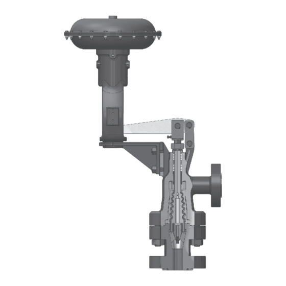
2. General The MIL 77000 Series is part of MIL’s severe throughout the complete throttling process service portfolio, and may be custom designed giving it two advantages : to fit our customer’s most difficult applications. Reduction of the noise produced by the... -
Page 4: Air Piping
(2), plug (3), Note : The above torque values are only and body (1). If necessary to lap the plug available for carbon steel bolting. In case to seat ring. of stainless steel bolts, consult KSB MIL. -
Page 5: Plug Stroke Adjustment
The plug reaches its wide open position when Caution : The spacing measured around the lever contacts the yoke adapter (21). When the periphery after final tightening of the lever is raised and the plug contacts the seat, the body nuts must be consistent with the plug travel should be that value shown in ±... -
Page 6: Mounting And Adjustment Of Actuator
Parts List Ref. No. Part Name Ref. No. Part Name Valve Body Actuator Bracket Seat Ring Bracket Stud Hélicoflex® Stud Nut Valve Plug Yoke Adapter Bottom Flange Stem Adapter Drive Nut Anti-rotation Screw Packing Follower Locknut Packing Flange Pipe Plug Packing Flange Stud Pin (Valve End) Stud Nut... -
Page 7: 38 Reverse Actuator (Air-To-Close)
stem adapter and link line up. Insert the Then screw stem adapter (22) by 6 to second pin (27), link (29) and snap rings 12 mm more into clamp. (32). Fit snap rings (31) and tight nut (60) Apply air pressure to the diaphragm to of the stem clamp (58). - Page 8 Figure 4 Split Stem Clamp 28 26 31 33 30 24 23 22 28 26 31 33 30 24 23 Figure 2 Figure 3 No. 38 Reverse Actuator No. 37 Direct Actuator (Increasing air retracts stem) (Increasing air extends stem) Parts List Part Name Ref.
-
Page 9: And 68- Piston Cylinder Double Acting Actuator
made. An additional 6 to 12 mm adjustment Note : The skive cut of each packing (step 4) of the stem adapter is unnecessary. With ring must be placed about 180 the reverse actuator, seating force is provided by degrees apart. air pressure above the maximum value of the spring range, so marking of the actuator stem is Replace packing follower (6) and... - Page 10 will be used to lap the plug to the seat. materials of construction, condition of The T handle may be made by drilling a the seating surfaces and accuracy of hole through a small piece of flat stock machining. and fastening to the threaded rod by two If a short period of lapping does not visibly locknuts.
- Page 12 Damage, if any, noticed to valve body and bonnet also should be replaced or repaired. After the life-cycle, we recommend to dispose the parts as per your established procedures, through approved agencies only. KSB MIL Controls Limited Meladoor, Annamanada, Pin - 680741 Thrissur District, Kerala, India Tel.
Need help?
Do you have a question about the MIL 77000 and is the answer not in the manual?
Questions and answers