Table of Contents
Advertisement
Quick Links
Instruction Manual
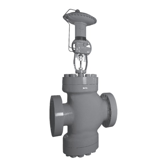
MIL 10000
Double Ported Top & Bottom Guided
Control Valves
Purchase Order No :
The following instructions should be thoroughly
reviewed and understood prior to installing, operating
or performing maintenance on this equipment.
Throughout the text, safety and/or caution notes will
appear and must be strictly adhered to, otherwise, serious injury
or equipment malfunction could result.
___________________________________________
Advertisement
Table of Contents

Subscribe to Our Youtube Channel
Related Manuals for KSB MIL 10000


Summary of Contents for KSB MIL 10000
- Page 1 Instruction Manual MIL 10000 Double Ported Top & Bottom Guided Control Valves Purchase Order No : ___________________________________________ The following instructions should be thoroughly reviewed and understood prior to installing, operating or performing maintenance on this equipment. Throughout the text, safety and/or caution notes will appear and must be strictly adhered to, otherwise, serious injury or equipment malfunction could result.
-
Page 2: Table Of Contents
Introduction........................2 General..........................3 Unpacking...........................3 Installation..........................3 Air Piping..........................4 Body Disassembly........................4 Maintenance / Repair......................4.. Valve Body Reassembly.......................7 Parts List..........................9 Note: Easily replaceable Pressure gauges for Air sets and externally mounted Pressure gauges of positioners are normally dismantled, separately packed and bound to the actuator yoke as a precaution against transit damages. -
Page 3: General
These installation and maintenance instructions guided valve for use at higher flow rates and apply to all sizes and ratings of the MIL 10000 pressure drops. The additional guiding reduces series control valves regardless of the type of the vibration of the plug, which if severe trim used. -
Page 4: Air Piping
Caution: Where insulation of the valve body is required, do not insulate the valve bonnet. Takenecessary protective measures for personal safety. 5. Air Piping Unless otherwise specified, the connection to the actuator tubing shall be 1/4" NPT or ½" Warning : Do not exceed supply pressure NPT. -
Page 5: Maintenance / Repair
7. Maintenance & Repair 7.3 Lapping Seats Lapping is the process of working the valve The purpose of this section is to assist plug against the seat ring with an abrasive to maintenance personnel by suggesting methods produce a close fit. When valve leakage of component maintenance which is largely becomes excessive, lapping becomes dependent on the tools and machine shop... - Page 6 Install bottom flange (11), ensuring Note : Seat repair in a double seated bottom bushing (15) is in place and secure valve is critical. In a new valve the to the body using 4 body stud nuts (6, 7) distance between the upper and lower spaced equally apart.
- Page 7 (8). 7.4.Plug Stem Pinning Unscrew the plug from the stem (counter Valve plug and stem assemblies are normally clock-wise). furnished as a complete assembly in which case Cut off the stem directly above the pin the installation involves no problem. It is only hole.
- Page 8 amount of grease on it and press into the Place the plug guide on a V block and hole. using a suitable size drill, drill the stem using the hole in the plug as a guide. I. After the plug has been pinned it should be Remove any burrs from the plug guide by placed in a lathe to ensure it is running making a slight counter bore.
-
Page 9: Valve Body Reassembly
8. VALVE BODY REASSEMBLY (For Valve <= Class II leakage) It is possible to change the valve from down Install bonnet gasket (12), bonnet (5) and seating to up seating or vice versa. However, the loosely install body stud nuts (6, 7). plug stem must be repinned to the opposite end of the plug. - Page 10 Parts Reference PART NAME DRAWING Ref No. PART NAME DRAWING Ref No. Plug Stem Blind Flange Packing Flange Nut Body Gasket Lower Seat Ring Packing Flange Upper Seat Ring Packing Flange Stud Guide Bush 5,10 Bonnet, Body Packing Spacer Body Stud Body Nut Packing Packing Follower...
- Page 12 Damage, if any, noticed to valve body and bonnet also should be replaced or repaired. After the life-cycle, we recommend to dispose the parts as per your established procedures, through approved agencies only. KSB MIL Controls Limited Meladoor, Annamanada, Pin - 680741 Thrissur District, Kerala, India Tel.
Need help?
Do you have a question about the MIL 10000 and is the answer not in the manual?
Questions and answers