Table of Contents
Advertisement
Quick Links
Operating Instructions
8613.81/7- EN
1.
Declaration of conformity
2.
General
3.
Safety
4.
Transport and interim storage
5.
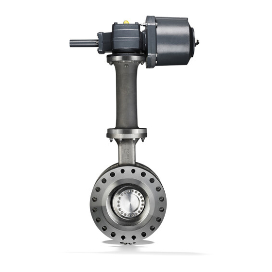
Description of valves
6
Installation
7.
Commissioning / Decommissionning
8
Maintenance / Repair
9.
Trouble shooting
TRIODIS 150
TRIODIS 300
TRIODIS 600
TRIODIS 900
MT and TBT versions
2
4
4
5
6
11
15
16
17
42810916
Advertisement
Table of Contents

Summary of Contents for KSB TRIODIS 150
- Page 1 Operating Instructions 8613.81/7- EN TRIODIS 150 TRIODIS 300 TRIODIS 600 TRIODIS 900 MT and TBT versions Declaration of conformity General Safety Transport and interim storage Description of valves Installation Commissioning / Decommissionning Maintenance / Repair Trouble shooting 42810916...
-
Page 2: Declaration Of Conformity
Declaration of conformity Hereby we, KSB S.A.S. Zone industrielle Gagnaire Fonsèche 24490 LA ROCHE CHALAIS Registered Office: 92635 - Gennevilliers France declare that the valves listed below comply: with the requirements of the Pressure Equipment Directive 2014/68/EU Description of the valve types:... - Page 3 with the requirements of the regulation EC REACH 1907/2006. Regulation EC 1907/2006 on the registration, evaluation, authorization and restrictions of chemicals Description of the valve types: Butterfly valves -- TRIODIS MT class 150 DN 50 - 600 class 300 DN 80 - 1200 class 600 DN 150 - 1000...
- Page 4 These operating instructions apply to KSB offset disc butterfly valves Safety instructions put forth in this instruction manual, the Design, manufacturing and testing of the KSB valves are subject to a nonobservance of which would involve the risk of personal injury, they...
- Page 5 3.6. Safety lnstructions for Maintenance, Inspection and Installation work 3.6.1. General The user is responsible for ensuring that all maintenance, inspection and installation work is carried out by authorized, adequately qualified staff who are thoroughly familiar with this instruction manual. Any work on a valve may only be performed when the valve is un-pressurized and has cooled down to 60 °...
- Page 6 Drawings and documents 50 - 5.2.1 MT version (average temperature) 72 - Type Size (mm) Type series booklet no. 50 - TRIODIS 150 MT 50 - 600 8465.53 TRIODIS 300 MT 80 - 1200 8613.1783 TRIODIS 600 MT 150 - 1000 8613.1786...
- Page 7 Disc drive with splines Cl. 300: DN 16” 901.1 Cl. 600: DN 8” and 10” Cl. 900: DN 10” 554.1 13- 21 Detail A 901.3 901.6 930.1 Detail B 41- 2.1 Detail B 310.1 554.4 Detail A 412.1 310.2 412.2 412.3 Detail C...
- Page 8 Cl. 150: DN 8” to 42” (Buttweld Side Entry version) 5.2.2 TBT version (very low temperature) Type Size (mm) Type series booklet no. Detail A TRIODIS TBT Class 150 80 - 1200 8465.53 13- 21 TRIODIS TBT Class 300 80 - 1200 8613.1783 554.2 TRIODIS TBT Class 600...
- Page 9 Disc drive with splines Cl. 300: DN 16” 901.1 Cl. 600: DN 8” and 10” Cl. 900: DN 10” 554.1 13 - - 21 Detail A 901.3 930.2 Detail B 930.1 310.1 554.4 Detail B 41 - - 2.1 412.2 415.2 412.1...
-
Page 10: List Of Components
5.3. List of Components Parts list for TBT version Part No. Name of Parts Some parts does not exist for all versions 01- 48 Sealing packing Body 13- 21 Extension Parts list for MT version Seat Part No. Name of Parts Cover 01- 48 Sealing packing... -
Page 11: Installation Conditions
5.4. Functioning principle TRIODIS 150 Installation Description 6.1. General The valve consists mainly of a body (100), operating shaft (213), shaft ATTENTION To avoid leakage, deformation or rupture of the body, (210) and disc (550). the piping should be laid out in such a way that no thrust or bending... - Page 12 6.2.2. Flanging dimensions 6.2.2.2. Flanged type body ( T7) Class 150 / 300 / 600 / 900 Connection to the piping. 6.2.2.1. A n n u l a r ( T 1 ) & Piping flanges must match the following dimensions. Full - - lug type body (T4) - Class 150 / 300 / 600 Connection to the piping.
- Page 13 MT and TBT version / Class 300 6.2.3. Flange gasket Disc clearance Size The dimensional compatibility of the flange gasket must be checked to ensure the connection quality, according to the dimensions defined hereunder: 6.2.3.1. MT and TBT versions / Class 150 / 300 / 600 / 900 Annular (T1) &...
- Page 14 ASME B16.5 EN 1092 PN40 6.2.4. Bolting ASME B16.5 EN 1092 PN40 Length of bolting are defined in Type series booklet. KSB ASME B16.5 recommends : EN 1092 PN40 to follow this length in order to maximize threaded ASME B16.5 length.
-
Page 15: Recommendations For Installation
- Verify that pipeline flanges are located on the same centerline and are parallel. Use only lifting rings delivered by KSB (lifting lugs - Verify that dimensions of gaskets flange are compatible with paints according to DIN 580 not allowed) the dimensions mentioned in the table 6.2.3. -
Page 16: Safety Instructions
Prior to possible transport, the valves must be flushed and drained Commissioning/Decommissioning carefully. lf you have any questions please contact your KSB 7.1. Commissioning Sales Office. 7.1.1. General lf actuators powered by an external source of energy Prior to commissioning the valve, the pressure, temperature... -
Page 17: Troubleshooting
Check type and flange bolting torque Wrong flanging size Follow instructions given in KSB technical leaflet Wrong face to face, Flanging has to be modified in accordance with KSB technical leaflet non-parallel flanges requirements. Flow conditions Check the technical offer versus service conditions... - Page 18 Notes...
- Page 19 Notes...
- Page 20 TRIODIS 150 / 300 / 600 / 900 KSB S.A.S. 4, allée des Barbanniers 92635 Gennevilliers Cedex (France) Tel.: +33 1 41 47 75 00 Fax: +33 1 41 47 75 10 www.ksb.com...


Need help?
Do you have a question about the TRIODIS 150 and is the answer not in the manual?
Questions and answers